iii
Summary
This thesis is part of the i-Botics project. It is founded as an independent research center by TNO and University of Twente. The research is mainly concerned with interaction robotics, namely telerobotics and exoskeletons.
Telerobotics deals with remote controlled robots. These robots are send to remote location without the operator of the robot being present. Telepresence and teleoperations are used to allow the operator to control the robot with remote presence. To achieve this remote presence for the operator, several technological approaches can be used. Haptics is one of these. This thesis is a design oriented project within the telerobotics research field of i-Botics. The goal of this thesis is to create an haptic interface between a robotic hand (ReFlex TakkTile) -mounted on a remotely controlled robot - and the control unit for the user (Omega 7 Haptic Device). This haptic interface is created to allow the user to do remote manipulation. This should allow for interaction with objects which are in the remote environment.
First, an analysis was done to investigate possible implementations for the haptic interface. Both side of the haptic interface were investigated based on their control possibilities. From that point onwards, a bond graph approach was used to identify four possible haptic inter-faces. Based on the available hardware, an impedance type and direct type interface are suit-able. These interfaces are the control layers between the ReFlex TakkTile and the Omega 7. In the implementation phase, both haptic interfaces were constructed and tested. The inter-faces were implemented using a Robot Operating System (ROS) as middleware. This allows for easy communication between the robotic hand and the control unit. During the con-struction of the impedance type interface it became clear that it was not a suitable interface, because the force control of the ReFlex TakkTile did not respond well. Therefore, the direct approach was chosen for the remainder of the project. This interface was successfully imple-mented.
v
Samenvatting
Deze scriptie is onderdeel van het i-Botics project. Dit project is opgericht door TNO en Uni-versiteit Twente als onafhankelijk onderzoekscentrum. De focus van het onderzoek is gericht op interactie robotica. In het specifiek: telerobotica en exoskeletons.
Telerobotica houdt zich bezig met op afstand bestuurbare robots. Deze robots worden naar afgelegen locaties gestuurd zonder dat de bestuurder daar daadwerkelijk aanwezig is. Telep-resentie en teleoperaties kunnen worden gebruikt om de bestuurder van de robot meer het gevoel te geven dat hij of zij daadwerkelijk bij de robot aanwezig is of zelfs de robot kan ’zijn’. Meerdere technologieën kunnen worden gebruikt om deze graad van ’situationeel bewustz-ijn’ te creëren. Haptics is één van de mogelijkheden.
Deze scriptie is ontwerp geörienteerd en is een onderdeel binnen het onderzoeksgebied van de telerobotica. Het doel van deze scriptie is om een haptische interface te maken tussen een robot hand (ReFlex Takktile) - die gemonteerd is op een op afstand bestuurbare robot - en een besturingseenheid (Omega 7 Haptic Device). Deze haptische interface is gemaakt om de bestuurder in staat te stellen de robot op afstand te besturen. Hierdoor kan de bestuurder interactie hebben met voorwerpen die de robot vast kan pakken.
Eerst is een analyse gedaan naar mogelijke implementaties van de haptische interface. Er is gekeken naar beide kanten van de interface om te kijken naar mogelijkheden voor de aans-turing. Met behulp van bondgraaf technieken zijn vier interfaces geïdentificeerd. Twee van deze vier interfaces werden geacht positieve resultaten te geven gebaseerd op beschikbare hardware. Dit zijn de impedantie interface en de directe interface aanpak. Deze interfaces vormen een plek waarin regeltechniek toegepast kan worden tussen de ReFlex TakkTile en de Omega 7.
vii
Contents
1 Introduction 1
2 Background 3
2.1 Haptic feedback . . . 3
2.2 The robotic setup . . . 4
2.3 Omega 7 haptic device . . . 6
3 Requirements 9 3.1 System requirements . . . 9
3.2 MoSCoW . . . 9
4 Analysis 11 4.1 Haptic feedback interface . . . 11
4.2 Control schemes . . . 14
5 Design & implementation 17 5.1 Control structure . . . 17
5.2 Implementation . . . 19
6 Results 23 6.1 Testing setup . . . 23
6.2 Results . . . 24
7 Discussion 31 7.1 Position ReFlex TakkTile . . . 31
7.2 Sensor data ReFlex TakkTile . . . 32
7.3 Testing circumstances . . . 32
7.4 Force feedback . . . 32
8 Conclusion 33
9 Recommendations 35
1
1 Introduction
This assignment is part of a large robotic project at the i-Botics lab. The aim of this project is to create a robot which can be operated from a remote location to achieve a manipulation task. The robot consist out two RMP omni 50 systems which make up the base of the robot. Furthermore, a robotic arm (KUKA LWR 4+) is mounted on the base. This arm has a gripper (ReFlex TakkTile) connected to it. The robot is controlled from a control unit (Leo Universal Cockpit) and it gives the user audio, video and haptic feedback. Part of this control unit is an Omega 7 Haptic device which allows the user to control the robotic arm and gripper. The goal of this bachelor assignment is to create the haptic feedback interface between the Omega 7 haptic device and the ReFlex TakkTile.
The robotic hand has multiple pressure sensors in every finger to register interaction with the environment. This data can be used to provide haptic feedback to the user through the Omega 7 Haptic Device. This means that if the fingers of the ReFlex TakkTile hit an object, the user feels this object by means of force feedback in the Omega 7 Haptic Device. The goal of this assignment is to achieve reliable and realistic haptic feedback of the gripping action of the robotic hand. Although the ReFlex TakkTile has 4 degrees of freedom, only 3, controlled as one, degrees of freedom are used during this assignment. To create this haptic feedback a robust program needs to be developed in order to control the robotic hand appropriately. Currently, the robot runs on a Robotic Operating System (ROS) and is programmed in C++. Since the robot is designed to be modular, the code should also be modular. This means that programming should be done ’component-based’ and that all the software should be reusable and independent of ROS.
To create this haptic interface a bond graph approach is used. This is a port-based modeling approach which is energy based and is a domain independent technique which allows inter-connection between different domains (Mersha, 2014). The bond graph approach was used to identify four possible haptic interfaces. These interfaces are the control layers between the ReFlex TakkTile and the Omega 7. From the bond graphs, the corresponding control structures are derived. Based on early tests and analysis on the available hardware, a control structure was chosen to be implemented. The software is developed in ROS. The final demo allows the user to feel the gripping force of the ReFlex TakkTile while the the robot is situated at a remote location.
conclu-3
2 Background
This section consists out of two parts. First, different types of haptic feedback will be ad-dressed. This will give insight in how the user can experience these different types of haptic feedback. Then an overview is given of the setup that is used during this thesis project. Espe-cially, the ReFlex TakkTile and the Omega 7 haptic device will be discussed there.
2.1 Haptic feedback
There are different approaches possible when it comes to providing haptic feedback to the user. Which type of haptic feedback is suitable, depends on the application. This section elaborates on different types of haptic feedback that are used most often.
2.1.1 Cutaneous feedback
This type of feedback can be perceived through the skin. There are lots of receptors in the skin which allow for this perception. Cutaneous feedback can be further subdivided into the following types of feedback which all can be perceived through the skin.
Tactile feedback
Tactile feedback allows humans to perceive pressure patterns on the skin. Therefore, hu-mans are able to identify the shape and texture of objects. For this reason, tactile feedback is considered to be a very important type of haptic feedback for humans (Rubin, J., 2016).
Vibrotactile feedback
This is also called vibration feedback. This is a logical name since vibrotactile is all about vibrations. Humans are capable of detecting vibrations on the skin up to 1000 Hz. This means that the human skin is able to ’feel’ sounds under the right conditions (Rubin, 2016a). Usually, this feedback is implemented by the use of vibrating actuators. Changes in pulse width and pulse rate can be used to modulate the intensity of the vibration (Chatterjee, 2008).
Thermal feedback
2.1.2 Force feedback
This type of feedback is perceived through muscles. There are lots of sensory organs present in the human muscles which can react to forces acting on the musculoskeletal system. With these sensory organs, humans are able to perceive force feedback.
In contrast to cutaneous feedback, force feedback applies forces to the user on larger parts of the body such as a finger or an arm. This is caused by the fact that the sensory organs in the muscles cannot pick up small changes in a muscle. For this reason, force feedback devices are usually much larger than cutaneous feedback devices.
Furthermore, there is a difference between resistive and active force feedback devices. Re-sistive haptic devices block certain movements the user wants to make. This restricts the motion of the user. Active force feedback does this as well, but it also can guide the user in the right direction by actively moving their body around. (Rubin, 2016c).
2.2 The robotic setup
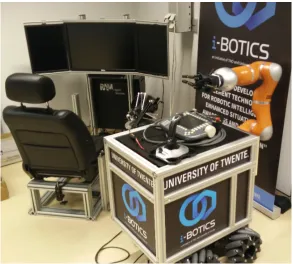
[image:12.595.169.463.396.660.2]CHAPTER 2. BACKGROUND 5
2.2.1 Base
The base of the robot consist of a large box which holds the processors and batteries to power the robot. This box is placed on top of two RMP omni 50 segway systems which allows the robot to move omni-directionally. The two segway systems are rigidly connected to form a solid base. The wheels of the robot are chosen to be omni-directional wheels and can be driven independently from each other.
2.2.2 KUKA LWR 4+
On the side of the base of the robot, a robotic arm is mounted to allow the user to interact with the environment. The arm was chosen to be a KUKA LWR 4+, where LWR stands for Light Weight Robot. It is a LWR robot since it is only 16 kg while still being able to handle a 7 kg load. Furthermore, the arm has 7 degrees of freedom (DOF) and the working envelope of the arm has a volume of 1.84m3(KUKA, 2012).
2.2.3 Reflex Takktile
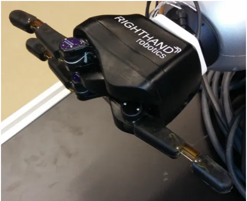
At the end of the KUKA LWR robotic arm, a robotic hand is mounted. This hand is a ReFlex TakkTile and is visible in Figure 2.2. ReFlex Takktile has three fingers which contain 9 pres-sure sensors each. The hand is underactuated which means that it has a lower number of actuators than DOF (RightHandRobotics, 2017).
[image:13.595.154.406.455.660.2]In the context of this assignment it is important that pressure sensor values can be ob-tained from the ReFlex Takktile to determine if an object is touched/grabbed. Furthermore, the actuators of the finger should be controlled as well. There are different control modes available on the ReFlex TakkTile. It is possible to use position, velocity and force control (RightHandRobotics, 2016).
Figure 2.3 gives an overview of the layout of the ReFlex Takktile. There are three fingers on the hand labeled from 0 to 2. Each finger consist out of a proximal phalanx and a distal phalanx. Pressure sensor are placed inside those phalanges, labeled from 0 to 8. Pressure sensor 8 is placed at the tip of the finger. Every finger is driven by a motor and are also labeled from 0 to 2.
Figure 2.3:Layout of the ReFlex TakkTile
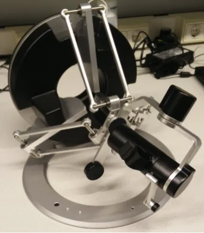
2.3 Omega 7 haptic device
CHAPTER 2. BACKGROUND 7
[image:15.595.72.275.263.494.2](a)The total Omega 7 system (b)The gripper of the Omega 7
9
3 Requirements
This section gives an quick overview of the requirements of the system. It also shows the importance of every aspect of the system by means of a MoSCoW.
3.1 System requirements
Since this thesis is design oriented, it can be seen as applied research. The following system requirements can be seen as a starting point for the design.
1. The user should be able to control the speed or force of grasping
2. The Omega 7 should give force feedback when there is interaction with the environ-ment
3. The haptic interface should work via a wireless data link
4. The three fingers of the ReFlex TakkTile should be controlled by one gripping action of the Omega 7
5. The fingers of the ReFlex TakkTile should wrap around an object 6. The grasping execution time should not disturb the user
Most of these requirements follow from the perspective of the user. That is, the user should be in control in all times. Furthermore, the haptic response of the interface should be an immersive experience to the user.
3.2 MoSCoW
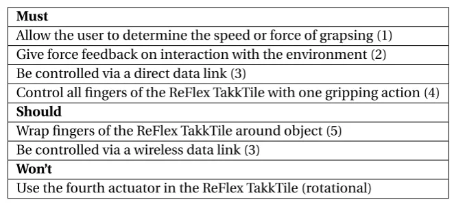
[image:17.595.112.453.528.677.2]Following from the system requirements, a MoSCoW table is constructed. Table 3.1 indicates the importance every aspect of the system under design. The numbers between brackets in correspond to the system requirements of Subsection 3.1. The last row of Table 3.1 does not correspond with any of the systems requirements since this is a ’Won’t’ condition. The rotational actuator inside the ReFlex TakkTile will not be used in the system under design.
Table 3.1:MoSCoW for system under design
Must
Allow the user to determine the speed or force of grapsing (1) Give force feedback on interaction with the environment (2) Be controlled via a direct data link (3)
Control all fingers of the ReFlex TakkTile with one gripping action (4) Should
Wrap fingers of the ReFlex TakkTile around object (5) Be controlled via a wireless data link (3)
Won’t
11
4 Analysis
4.1 Haptic feedback interface
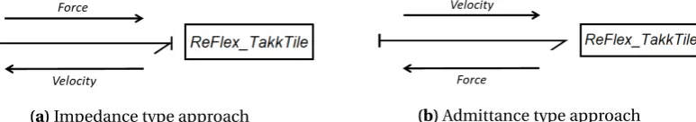
The Reflex TakkTile and the Omega 7 both can be seen as energy ports which can exchange energy with the user and the environment respectively. Figure 4.1a and 4.1b give two possible causality assignments for the ReFlex TakkTile when bond graphs are applied. With effort-in causality, the ReFlex TakkTile receives a force to drive the actuators. This will result in a veloc-ity(Figure 4.1a). This is called an impedance type approach. The inverse is also possible, i.e. receiving a velocity and having a force as an output (Figure 4.1b). This is called an admittance type approach.
[image:19.595.94.481.276.344.2](a)Impedance type approach (b)Admittance type approach
Figure 4.1:Impedance and admittance type approaches
When choosing between an impedance or admittance type approach, there are two impor-tant considerations. One of them is the suitability of the device. For example, it is imporimpor-tant to examine if the ReFlex TakkTile is able to be driven by force control and/or velocity control. The same holds for the ability to read out the force and/or velocity from the ReFlex TakkTile. Another consideration is the environment the device will encounter. Namely, if the environ-ment the device will encounter be soft or stiff.
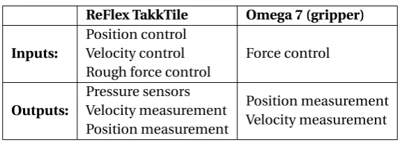
It is important to see if it is actually possible to actuate the ReFlex TakkTile and Omega 7 with a force or velocity as input and if it feasible to obtain the velocity and force. Table 4.1 gives an overview of the possible inputs and outputs of the ReFlex TakkTile and the Omega 7. From the table it is clear that both approaches can be used for the ReFlex Takktile. The Omega 7 only allows for force control as an input so only the impedance type approach can be used.
Table 4.1:Inputs and outputs of the ReFlex TakkTile and Omega 7 (RightHandRobotics, 2016)
ReFlex TakkTile Omega 7 (gripper) Inputs:
Position control Velocity control Rough force control
Force control
Outputs:
Pressure sensors Velocity measurement Position measurement
Position measurement Velocity measurement
An important aspect to note is that the actuators need to be driven inside the ReFlex TakkTile and the Omega 7. These actuators need a force/torque input, so a position/velocity cannot simply be dictated. In case of position and velocity control, control loops are applied to allow position/velocity input based on which force on the actuators is calculated. These control loops run on the hardware itself.
CHAPTER 4. ANALYSIS 13
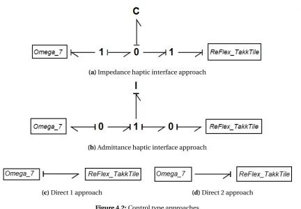
(a)Impedance haptic interface approach
(b)Admittance haptic interface approach
[image:21.595.68.501.99.399.2](c)Direct 1 approach (d)Direct 2 approach
Figure 4.2:Control type approaches
[image:21.595.93.469.497.557.2]Table 4.2 gives a total overview of the possible haptic interfaces. The choice on which type of haptic interface is suitable for this thesis depends on the two sides of the interface and if they can best be used in impedance or admittance mode i.e. effort-in or flow-in.
Table 4.2:Types of control
Omega 7
ReFlex TakkTile
effort-in flow-in
effort-in Impedance control Direct 1
flow-in Direct 2 Admittance control
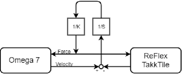
4.2 Control schemes
The resulting haptic interfaces, impedance control and direct 1 control, can be converted to control schemes. To do this, the bond graphs can be converted to signal graphs. The impedance type interface in Figure 4.2a is converted to a signal graph in Figure 4.3a, or, equivalently, the control scheme in Figure 4.3b. When the user interacts with the Omega 7, they are dictating a velocity(V0). The force(F) that is send to ReFlex is computed from the difference between the reference velocity(V0) and the actual velocity of the fingers(Vac t ual).
The force that is send to the ReFlex is also used as force feedback to the user(Fhap t i c).
[image:22.595.170.462.239.359.2]CHAPTER 4. ANALYSIS 15
Figure 4.4:Direct control approach
17
5 Design & implementation
For the design, there are two major parts which will be discussed in the following subsections; how the control structure is implemented and how the software is structured.
5.1 Control structure
The control structure that was implemented is the direct control structure. It is shown in Fig-ure 5.1. Between the Omega 7 and the ReFlex TakkTile mapping is included to convert the single DOF of the gripper to the multi-DOF fingers of the ReFlex. Furthermore, mapping is included to convert the pressure sensor data to force feedback for the user. A clear difference is the shift from velocity control to position control. During early test, the ReFlex behaved much more consistently when driven by position control. Equation 5.1 and Equation 5.2 show position control and velocity control respectively. These equations show that intrinsi-cally, these approaches are the same. Since the position control behaved better, this change was made in the control structure.
Fpos=KP·x+KD·x˙ (5.1)
Fvel=KP
Z
[image:25.595.75.492.331.525.2]v+KD·v (5.2)
Figure 5.1:Control scheme for the haptic interface
5.1.1 Mapping gripper to ReFlex TakkTile
5.1.2 Mapping pressure sensor data to force feedback
The pressure data from the sensors should also be mapped back to force feedback for the gripper. The initial approach was to directly map the data from the pressure sensors to force feedback for the gripper of the Omega 7. However, by using this approach, the user also re-ceived force feedback when moving the fingers of the ReFlex away from the object. Combined with the delayed mapping from the gripper of the Omega 7 to the fingers of the ReFlex, this resulted in an unnatural response. All in all, the response of the interface was not satisfac-tory using the direct force mapping from the pressure sensors of the ReFlex to the Omega 7. Therefore, an alternate approach was used to overcome this problem.
Since there are 27 force sensors in the hand, averaging is used to reduce the complexity of the problem. The data coming from 4 pressure sensors in a distal phalanx and 5 pressure sensors from a proximal phalanx are averaged. Since the contact area of every phalanx is small com-pared to the total size of the ReFlex and the ReFlex is most likely to encounter large objects, it is assumed that averaging these values is acceptable. In this way, the 27 force sensor values are converted to 6 averaged values. These 6 values correspond to the 6 phalanges of the Re-Flex.
The interface decides if the fingers touch an object by means of a force threshold. Every phalanx with its corresponding averaged value from the pressure sensors is compared to the force threshold. If the threshold is crossed, the current position of the gripper of the Omega 7 is saved as a reference. This is done to increase the stability of the system. The stability in-creases because the force feedback is not dependent on position of the fingers anymore. By means of Hooke’s law (Equation 5.3), the force feedback is determined. The stiffness factor is determined empirically and in such a way that it works best with stiff environments.
F= −K(x−xr e f) (5.3)
Re-CHAPTER 5. DESIGN & IMPLEMENTATION 19
Figure 5.2:Forces applied on objects by the fingers of the ReFlex TakkTile. The black box represents an object and the force vectors mark the points where the fingers apply pressure.
5.2 Implementation
This subsection gives and overview of the software implementation. Besides the implemen-tation of the control structure, other important aspects, which influenced the final product, are explained. The implemented software can be found in Appendix A.
[image:27.595.71.487.501.587.2]5.2.1 Structure
Figure 5.3 shows the structure of the software in ROS. The software implementation sits right between the ReFlex TakkTile and the Omega 7 as its own node. To obtain the data from the Omega 7, the interface uses the functions in the header file of the Omega 7. The header file of the Omega 7 is included in the main file of the interface. By using this method, the position of the gripper is obtained directly and the force feedback is set directly as well by using the functions from the header file. The interface communicates via topics with the ReFlex to obtain the force sensor values and to command the position of the hand.
5.2.2 Refresh rate
During early tests, it came clear that the ReFlex was not able to follow the position of the gripper fast enough. To find a explanation for this, the ROS package of the ReFlex was further examined. In this package, the driver node can be found. Three hard coded time delays can be found inside the function which drives the motors. All these time delays add up to 0.09 seconds. According to the documentation, these time delays are needed to prevent the brain board of the ReFlex from freezing. Therefore, the refresh rate of the program was adjusted to account for these internal delays. A rate of 15 Hz seemed to provide a good response.
5.2.3 Initialisation procedure
[image:28.595.108.521.370.514.2]The startup of the interface requires the initialization of nodes, publishers and subscribers. Furthermore, it detects the Omega 7 and initializes it. The ReFlex is calibrated using the services of the ReFlex node. The initialization of the Omega 7 is designed in such a way that the user can insert his/her finger in the gripper without the actuation of the ReFlex TakkTile. This is achieved by applying a force on the gripper to close it. If the user counters this force by moving his/her finger outward, the program starts. In this way, the position of the gripper matches the open position of the ReFlex. Figure 5.4 gives an overview of the total initialisation procedure.
CHAPTER 5. DESIGN & IMPLEMENTATION 21
5.2.5 Mapping pressure sensor data to force feedback
The second part of the interface is the mapping of the sensor values from the pressure sensor to useful force feedback for the gripper of the Omega 7. Figure 5.5 gives an overview of the mapping process for the force feedback.
At the start of the mapping process, a distinction is made between the distal and proximal phalanx of a finger. If the distal phalanx of the finger passes the force threshold first, then only the averaged pressure sensor value from this phalanx contributes to the force feedback. The same holds for the proximal phalanx. Then a reference position of the gripper of the Omega 7 is saved. This is also done for every finger. By using Hooke’s law from Equation 5.3, the force feedback from every finger is calculated.
However, if the distal phalanx passes the force threshold after the proximal phalanx, both phalanges contribute to the force feedback. This is achieved by scaling the stiffness factor of Equation 5.3. This gives the impression of a tighter grip. By using this method a distinction is made between a pinch and a full grasp.
[image:29.595.74.491.382.639.2]The procedure described above is done for every finger, in every iterations of the program. The force feedback deducted from every finger is then averaged again by using the weighted average. The resulting force feedback is send to the gripper of the Omega 7. When the posi-tion of the gripper passes the reference posiposi-tion of a finger, the force feedback is disabled for this finger.
5.2.6 Drift prevention
Furthermore, it was found that when interacting with an object, the values from the pressure sensors start to drift. Figure 5.6a shows the drift phenomena of the pressure sensors. When the object is released at t=7.5, the sensor values do not return to zero due to drift. To overcome this problem, the pressure sensors of the ReFlex TakkTile are re-calibrated. The re-calibration is done when the pressure sensor values are below the force threshold. This is done to make sure that the fingers are not touching an object when re-calibrating. Figure 5.6b shows the sensor drift with prevention. After t=8.3, the sensor values return to zero every 20 iterations of the program.
6 6.5 7 7.5 8 8.5 9 9.5 10 10.5 11
Time(s) -2
-1.5 -1 -0.5 0 0.5 1 1.5 2
Pressure sensor data
Sensor drift, without prevention
Force proximal 0 Force proximal 1 Force proximal 2
(a)Drift of the pressure sensors, without drift prevention
1 1.5
2 Sensor drift, with prevention
[image:30.595.112.521.238.420.2]23
6 Results
This section will show the testing setup and how the results are obtained. Different testing situations are created to test the system.
[image:31.595.75.480.296.459.2]6.1 Testing setup
Figure 6.1a shows the testing setup for the ReFlex TakkTile. The hand is removed from the robotic arm to make testing more convenient. The ReFlex is placed on top of a small box to still be able to connect the power cord and the ethernet cable. To test the setup, a hard plastic bottle was used. To account for smaller objects, a computer mouse was used. The Omega 7 was used just as it is. Figure 6.1b shows the position of the user in the gripper of the Omega 7. Both sides of the interface were connected to a laptop.
(a)The testing setup for the ReFlex TakkTile (b)The testing setup for the Omega 7
6.2 Results
The various plots in this subsection are produced using the bagfile functionality of ROS. The data of the bagfiles is processed using MATLAB.
Mapped finger position and encoder data
This test was conducted to test the ability of the ReFlex to follow the commanded input. The result from this test is visible in Figure 6.2. In this test, the fingers of the ReFlex were first closed and then opened again. The closing part of the fingers was executed in a slow manner, while the opening part was executed fast. From the plot it is clear that the ReFlex is able to follow the input well during slow execution. The difference does not exceed 0.5 rad in this phase. The fast execution phase shows a larger difference in position. The maximum difference there is -1.4 rad.
Furthermore, the ReFlex needs time to reach the commanded position. When the ReFlex is moving slow it takes on average 0.2 seconds to reach the desired position. This appears to be a constant delay. However, when moving fast, this time can increases to 0.5 seconds. This is observed in Figure 6.2 between t=6 and t=7. This is noticeable to the user and is due to the internal time delays of the driver of the motors in the ReFlex as discussed in Section 5. Also the internal position control is assumed to be part of this delay.
0.5 1 1.5 2 2.5
3 Position of the fingers
[image:32.595.110.518.376.620.2]CHAPTER 6. RESULTS 25
Contact dectection
This test was conducted to test the contact detection. The result is visible in Figure 6.3. Dur-ing this test, a full grasp was executed. Only the averaged sensor data from the fDur-ingers is plot-ted to avoid having too much lines in one single plot. The vertical black lines indicate the first contact of the proximal and distal phalanges respectively. The release of the object is marked with a vertical black line as well. The dashed horizontal line represents the force threshold. If this threshold is crossed, contact is detected. Furthermore, there are negative pressure sen-sor reading around 6.5 seconds. The cause for this is unknown, but it might be caused by the drift of the sensor as mentioned in Section 5. Due to the implemented re-calibration of the pressure sensors, this value returns to zero again.
0 1 2 3 4 5 6 7 8
Time(s) -10 -5 0 5 10 15 20 25 30 35 40 45
Pressure sensor data
Contact detection
Proximal contact Distal contact Object released
Force threshold
[image:33.595.73.484.251.492.2]Force proximal 0 Force proximal 1 Force proximal 2 Force distal 0 Force distal 1 Force distal 2 Detection
Omega position, finger positions and force feedback
This test was executed to verify the functionality of the total system. The result of this test is visible in Figure 6.4. This is the same test as the force mapping test. This means that the same bagfile was used during the processing in MATLAB. Again, the black lines indicate the first contact of the proximal and distal phalanges. The haptic interface shows correct behaviour. This means that the force feedback starts when an object is hit and it stops directly when the object is released.
0 1 2 3 4 5 6 7 8
Time(s) 0 1 2 3 Position fingers(Rad) Full grasp
Commanded finger position Encoder Finger position
0 1 2 3 4 5 6 7 8
Time(s) 0
20 40
Pressure sensor data
Force proximal 0 Force proximal 1 Force proximal 2
0 1 2 3 4 5 6 7 8
Time(s) 0
20 40
Pressure sensor data
Force distal 0 Force distal 1 Force distal 2
0 1 2 3 4 5 6 7 8
Time(s) 0
2 4
Force feedback(N)
Proximal contact Distal contact Object released
[image:34.595.108.525.213.460.2]Force feedback
CHAPTER 6. RESULTS 27
Partial & full grasp
This test was executed to test the difference between a partial grasp and a full grasp. A partial grasp means that only 2 fingers of the ReFlex are used when grabbing an object. The result of this test is visible in Figure 6.5. The first part of the graph corresponds to a partial grasp and the second part to a full grasp. In the first part, the lines of the proximal phalanx 1 and distal phalanx 1 register no pressure. This corresponds to the conducted test where only finger 0 and 2 were used to grab the object. When only 2 fingers are used, the difference in force feedback is clear compared to a full grasp. That is, less force feedback is send to the user. In the second part, the object is grabbed, released and then grabbed again quickly. This explains the two bumps in second part of the graph.
0 2 4 6 8 10 12 14 16
Time(s) 0 1 2 3 Position fingers(Rad)
Partial & full grasp
Commanded finger position Encoder Finger position
0 2 4 6 8 10 12 14 16
Time(s) 0
20 40
Pressure sensor data
Force proximal 0 Force proximal 1 Force proximal 2
0 2 4 6 8 10 12 14 16
Time(s) 0
20 40
Pressure sensor data
Force distal 0 Force distal 1 Force distal 2
0 2 4 6 8 10 12 14 16
[image:35.595.73.491.252.496.2]Time(s) 0 2 4 Force feedback(N) Force feedback
Pinched grasp
This test was executed to test the pinched grasp functionality. When executing a pinched grasp, only the tip of the fingers are used. The result of this test is visible in Figure 6.6. The position of the gripper of the Omega 7 is also plotted to show that the gripper to position mapping function properly. The closed position of the gripper corresponds to the open po-sition of the hand. Therefore, the popo-sition of the gripper shows inverse bahaviour compared to the mapped position for the ReFlex. Furthermore, the haptic interface shows correct be-haviour again. This means that the force feedback to the user is also significantly less (<1N). Since this is a pinched grasp, the sensor data from the proximal phalanges stays low. A thing to note is a decrease in the sensor values from finger 2 around 6.5 seconds. At that point, finger 2 released the object for a short period of time.
0 1 2 3 4 5 6 7 8 9 10
Time(s) 0 1 2 3 Position fingers(Rad) Pinch
Commanded finger position Encoder Finger position
0 1 2 3 4 5 6 7 8 9 10
Time(s) -10 0 10 20 30
Pressure sensor data
Force proximal 0 Force proximal 1 Force proximal 2
0 1 2 3 4 5 6 7 8 9 10
Time(s) -10 0 10 20 30
Pressure sensor data
Force distal 0 Force distal 1 Force distal 2
0 1 2 3 4 5 6 7 8 9 10
[image:36.595.112.525.268.510.2]CHAPTER 6. RESULTS 29
Different objects
The final test that was executed to show the difference between two different sized objects that are grabbed. The result of this test is visible in Figure 6.7. In the first part of the graph the same bottle was grasped as in the other experiments. In the second part, a small computer mouse was used. The haptic interface shows correct behaviour again. In the second part of the graph, the sensor data from the distal phalanges stays low, because the object is too small to be grabbed by the tip of the fingers. This also resulted in less force feedback compared to the first part of the graph.
0 2 4 6 8 10 12 14 16 18
Time(s) 0 1 2 3 Position fingers(Rad) Different objects
Commanded finger position Encoder Finger position
0 2 4 6 8 10 12 14 16 18
Time(s) 0
20 40
Pressure sensor data
Force proximal 0 Force proximal 1 Force proximal 2
0 2 4 6 8 10 12 14 16 18
Time(s) 0
20 40
Pressure sensor data
Force distal 0 Force distal 1 Force distal 2
0 2 4 6 8 10 12 14 16 18
[image:37.595.71.492.226.465.2]Time(s) 0 2 4 Force feedback(N) Force feedback
31
7 Discussion
The performed tests are discussed in this section. 7.1 Position ReFlex TakkTile
The first test was executed to test the ability of the ReFlex TakkTile to follow the commanded input position from the user. From this test is was clear that time delays were occuring. This ranged from 0.2 to 0.5 seconds and is depended on the speed of movement from the user. When moving slow, this delay is still acceptable and the user is able to receive accurate feedback. However, during fast movement, the position of the ReFlex does not match the position of the gripper anymore. This means that the user may receive force feedback too late. If the mapped position from the gripper of the Omega 7 to the fingers of the ReFlex results in an object being touched, it should result in force feedback. However, since there is position delay, the fingers are not touching the object yet. This means that pressure sensors do not register pressure and no force feedback is exerted on the gripper yet. This position delay is an essential part of the haptic interface and therefore affects the functionality of it.
A cause for the excessive delay in the fast movement phase might be that the dynamixel mo-tors of the ReFlex Takktile have a maximum velocity. It is found that the momo-tors receive a com-mand between 0 and 1023 from the driver. Where 0 means no movement and 1023 means maximum velocity. This command is based on the desired speed for the motors, the gear ra-tio of the motors and a velocity scaling factor. The command for the motors is saturated if the desired velocity command exceeds 1023. The command for the motors is given by equation 7.1.
command=vd esi r ed·
mot or_t o_j oi nt_g ear_r at i o
vel oci t y_sc al e (7.1)
Where, themotor_to_joint_gear_ratioequals 1.42 and thevelocity_scaleequals 0.01194 rad/s. The resulting command is a dimensionless quanity. Since the maximum command equals 1023, this means that the maximum vd esi r ed equals approximately 8.6 rad/s. This is the
upper limit of the speed of the fingers according to the software of the driver. The actual maximum velocity of the ReFlex TakkTile in the first test was approximately 3.5 rad/s. This is significantly less that the theoretical maximum velocity from the driver. Therefore, the software of the driver is unlikely to be the limiting factor.
7.2 Sensor data ReFlex TakkTile
During the tests, some phenomena were observed concerning the pressure sensors inside the fingers of the ReFlex TakkTile. As observed in Figure 6.3, 6.4 and 6.6, negative sensor readings occurred. The cause for these unusual readings is unknown, but it might be caused by the drift of the pressure sensors. This was also discussed in Section 5. While the sensors are re-calibrated when no object is touched, it is still possible for the sensor values to drift when an object is being touched.
7.3 Testing circumstances
During almost all tests, the same object was used. This was done to ensure uniform test results. A stiff object was used, because the robotic system is most likely to encounter stiff environments. However, in some circumstances, soft objects might be present as well. This was not tested and could have an impact on the functionality of the robot.
This also holds for the testing position of the ReFlex TakkTile. The fingers of the ReFlex were facing up during all tests. Other positions such as a vertical or an upside down position might be useful as well.
7.4 Force feedback
33
8 Conclusion
The goal of this assignment was to create an haptic interface between a ReFlex TakkTile and an Omega 7 haptic device. Several approaches have been examined and based on the hard-ware specifications, a direct haptic interface was implemented. Due to time delays inside the driver of the ReFlex Takkile, the response of the interface was not satisfactory. Therefore, the direct structure was changed to overcome this issue. This resulted in a stable interface. Tests were executed to test the functionality of the interface. From this, it was clear that the interface is best suited for stiff environments and that it functions optimal when the speed of the finger of the ReFlex Takktile is kept low.
Initial requirements were set for the interface in Section 3. All of these requirements were met, except from the grasping execution time. This should not disturb the user. However, when the speed of interaction is high, the interface does not respond adequately due too large time delays in the system.
35
9 Recommendations
Based on the conducted research, the following improvements of the setup are recom-mended.
The system has not been tested in the wireless configuration. In the testing setup, a wired connection was used. Due to time limitations the wireless setup was not tested. However, the current setup has shown promising results and it seems that the interface is able to function in a wireless setup. In the ReFlex TakkTile, a software wrapper takes care of the position con-trol of the robot. As mentioned in Section 5, this introduces time delay. However, the haptic interface responded well and in such a way that the user is not restricted by the movement of the ReFlex compared to the movement of the gripper of the Omega 7. Only when the user uses quick gripping action, delay is noticeable. If the user controls the gripper in a calm manner, the interface has potential to function wireless.
In the current configuration of the interface, the stiffness in Hooke’s law - which determines the force feedback - is constant. This means that user cannot distinguish between hard or soft objects. The current haptic interface is more reliable for solid objects. To overcome this problem, the stiffness of the interface must become dependent on the data from the pressure sensors and the position of the fingers. If the fingers cover more distance compared to the measured pressure from the sensors, the ReFlex most likely encounters a soft object. The dual also holds for solid object. Therefore, the stiffness is dependent on the change in force over the change in distance. The real challenge in this implementation lies in the stability, since the ReFlex does need to deal with time delays.
Furthermore, a change in the structure of the software in ROS would be a recommendation. Currently, the header file of the Omega 7 is directly included in the main file of the interface. To make the structure of the code more modular, an additional node should be created. This node should obtain the state of the Omega 7 and publish it on ROS topics. By using this approach, the interface node is completely isolated from the ReFlex TakkTile and Omega 7.
37
Appendix
A Software implementation
#include " ros / ros . h"
#include " s t d _ s r v s /Empty . h" #include < s t d l i b . h>
#include < s t d i o . h> #include <iostream > #include < s t r i n g > #include <math . h>
#include <geometry_msgs/ Twist . h> #include <geometry_msgs/ Vector3 . h> #include <std_msgs / Float64 . h> #include <reflex_msgs /Hand . h>
#include <reflex_msgs /VelocityCommand . h> #include <reflex_msgs /PoseCommand . h> #include <reflex_msgs /ForceCommand . h> #include " . . / . . / omega7/ include / drdc . h" #include " . . / . . / omega7/ include /dhdc . h"
#define REFRESH_RATE 15 / / 11−12 according to code of ReFlex , 15 seems to provide a good response
#define FORCE_THRESHOLD 2 . 0 #define MAX_GRIPPER_GAP 0.027 #define MAX_JOINT_ANGLE 3 . 4 #define STIFFNESS 600.0 #define NUM_FINGERS 3
#define NUM_PRESSURE_DISTAL 4 #define NUM_PRESSURE_PROXIMAL 5 #define SCALING 1 . 2
#define MAX_CNT 10 reflex_msgs : : Hand hand ;
geometry_msgs : : Vector3 actualGripperPose ; geometry_msgs : : Vector3 actualGripperForce ;
geometry_msgs : : Vector3 forceFeedback ; reflex_msgs : : PoseCommand r e f l e x _ p o s ; s t d _ s r v s : : Empty empty ;
double actualGripperGap ;
double refGripperGap [NUM_FINGERS ] ; double setForce [NUM_FINGERS ] ; double averageSetForce ;
double forceDistalPhalange [NUM_FINGERS ] ; double forceProximalPhalange [NUM_FINGERS ] ; double posFingers ;
double weightedAverage [ 3 ] = { 0 . 2 5 , 0 . 2 5 , 0 . 5 } ; bool hapticsOn [NUM_FINGERS ] ;
i n t cnt ;
void startupGripper ( ) {
/ / startup p r o c e s s f o r the gripper
bool quit = f a l s e;
/ / f o r c e i s s e t to −1.0 to c l o s e the gripper
/ / user can then place h i s / her f i n g e r in the gripper
dhdSetForceAndTorqueAndGripperForce ( 0 . 0 , 0 . 0 , 0 . 0 , 0 . 0 , 0 . 0 , 0 . 0 , −1.0) ;
ros : : Duration ( 0 . 1 ) . sleep ( ) ;
/ / when the user opens the gripper , e x i t the loop and the program s t a r t s
while ( ! quit && ros : : ok ( ) ) {
dhdGetGripperGap(&actualGripperGap ) ;
i f ( actualGripperGap > (MAX_GRIPPER_GAP − 0 . 0 0 1 ) ) {
CHAPTER 9. RECOMMENDATIONS 39
double map(double x , double in_min , double in_max , double out_min , double out_max ) {
/ / simple mapping function , maps input to defined output boundaries
double map = ( x − in_min ) * (out_max − out_min ) / ( in_max
− in_min ) + out_min ; return map;
}
void getPressureDataProximal ( ) {
/ / g e t data from proximal phalanx and average / / t h i s i s done f o r every f i n g e r
for (i n t i = 0 ; i < NUM_FINGERS; i ++) { double average = 0 . 0 ;
for(i n t j = 0 ; j < NUM_PRESSURE_PROXIMAL; j ++) { average = average + hand . f i n g e r [ i ] .
pressure [ j ] ; }
forceProximalPhalange [ i ] = average / NUM_PRESSURE_PROXIMAL;
} }
void getPressureDataDistal ( ) {
/ / g e t data from d i s t a l phalanx and average / / t h i s i s done f o r every f i n g e r
for (i n t i = 0 ; i < NUM_FINGERS; i ++) { double average = 0 . 0 ;
for(i n t j = NUM_PRESSURE_PROXIMAL; j < (
NUM_PRESSURE_PROXIMAL + NUM_PRESSURE_DISTAL) ; j ++) {
average = average + hand . f i n g e r [ i ] . pressure [ j ] ;
}
forceDistalPhalange [ i ] = average / NUM_PRESSURE_DISTAL ;
} }
void r e f l e x C o n t r o l ( ) {
/ / map gripper gap to a p o s i t i o n f o r the f i n g e r s
}
void omegaControl ( ) {
for (i n t i = 0 ; i < (NUM_FINGERS− 1) ; i ++) {
/ / pinch
i f ( ( forceProximalPhalange [ i ] < FORCE_THRESHOLD) && ( forceDistalPhalange [ i ] > FORCE_THRESHOLD) )
{
i f ( hapticsOn [ i ] == f a l s e) { hapticsOn [ i ] = true; refGripperGap [ i ] =
actualGripperGap ; } e l s e i f ( actualGripperGap >
refGripperGap [ i ] ) {
hapticsOn [ i ] = f a l s e; setForce [ i ] = 0 . 0 ; } e l s e {
setForce [ i ] = −STIFFNESS * ( actualGripperGap −
refGripperGap [ i ] ) ; }
/ / f u l l grasp
} e l s e i f ( forceProximalPhalange [ i ] > FORCE_THRESHOLD) {
i f ( hapticsOn [ i ] == f a l s e) { hapticsOn [ i ] = true; refGripperGap [ i ] =
actualGripperGap ; } e l s e i f ( actualGripperGap >
refGripperGap [ i ] ) {
CHAPTER 9. RECOMMENDATIONS 41
/ / no f o r c e
} e l s e {
hapticsOn [ i ] = f a l s e; setForce [ i ] = 0 . 0 ; }
}
/ / c a l c u l a t e the t o t a l f o r c e feedback using a weighted average
averageSetForce = 0 . 0 ;
for(i n t i = 0 ; i < (NUM_FINGERS − 1) ; i ++) {
averageSetForce += weightedAverage [ i ] * setForce [ i ] ;
} }
i n t main (i n t argc , char* * argv ) {
/ / s t a r t i n i t i a l i z a t i o n
std : : cout << " INITIALIZING . . . " << std : : endl ;
/ / i n i t i a l i z e node
ros : : i n i t ( argc , argv , " i n t e r f a c e " ) ; ros : : NodeHandle n ;
/ / s u b s c r i b e r
ros : : Subscriber hand_state = n . subscribe ( " r e f l e x _ t a k k t i l e / hand_state " , 1 , &hand_data ) ;
/ / p u b l i s h e r s
ros : : Publisher pub_pos = n . advertise <reflex_msgs : : PoseCommand>( " r e f l e x _ t a k k t i l e /command_position" , 1) ;
/ / p u b l i s h e r s t e s t i n g
ros : : Publisher pub_pos_gripper = n . advertise <
geometry_msgs : : Vector3 >( " t e s t i n g / pos_gripper " , 1) ; ros : : Publisher pub_force_gripper = n . advertise <
geometry_msgs : : Vector3 >( " t e s t i n g / force_gripper " , 1) ; ros : : Publisher pub_force_distal = n . advertise <
geometry_msgs : : Vector3 >( " t e s t i n g / f o r c e _ d i s t a l " , 1) ; ros : : Publisher pub_force_proximal = n . advertise <
geometry_msgs : : Vector3 >( " t e s t i n g / force_proximal " , 1) ; ros : : Publisher pub_finger_pos = n . advertise <geometry_msgs
ros : : Publisher pub_force_feedback = n . advertise <
geometry_msgs : : Vector3 >( " t e s t i n g / force_feedback " , 1) ;
/ / s e r v i c e s
ros : : S e r v i c e C l i e n t c a l i b r a t e _ f i n g e r s = n . s e r v i c e C l i e n t < s t d _ s r v s : : Empty>( " r e f l e x _ t a k k t i l e / c a l i b r a t e _ f i n g e r s " ) ; ros : : S e r v i c e C l i e n t c a l i b r a t e _ t a c t i l e = n . s e r v i c e C l i e n t <
s t d _ s r v s : : Empty>( " r e f l e x _ t a k k t i l e / c a l i b r a t e _ t a c t i l e " ) ;
/ / i n i t i a l i z e r e f l e x t a k k t i l e
c a l i b r a t e _ f i n g e r s . c a l l ( empty ) ; c a l i b r a t e _ t a c t i l e . c a l l ( empty ) ;
/ / s e t r e f r e s h r a t e
ros : : Rate r (REFRESH_RATE) ;
/ / required to change asynchronous operation mode
dhdEnableExpertMode ( ) ;
/ / open the f i r s t a v a i l a b l e device
i f ( drdOpen ( ) < 0) {
p r i n t f ( " e r r o r : cannot open device (%s ) \n" , dhdErrorGetLastStr ( ) ) ;
dhdSleep ( 2 . 0 ) ; return −1; }
/ / p r i n t out device i d e n t i f i e r
i f ( ! drdIsSupported ( ) ) {
p r i n t f ( "unsupported device \n" ) ; p r i n t f ( " e x i t i n g . . . \ n" ) ;
CHAPTER 9. RECOMMENDATIONS 43
p r i n t f ( " e r r o r : r e g u l a t i o n thread f a i l e d to s t a r t (%s ) \n" , dhdErrorGetLastStr ( ) ) ;
dhdSleep ( 2 . 0 ) ; return −1; }
/ / stop a x i s c o n t r o l ( and leave r e gu l a t i on thread running )
drdStop (true) ;
/ / gripper i n i t i a l i z a t i o n
std : : cout << " PLACE HAND IN GRIPPER . . . " << std : : endl ; startupGripper ( ) ;
/ / end i n i t i a l i z a t i o n
std : : cout << " READY " << std : : endl ; while ( ros : : ok ( ) ) {
/ / g e t data from r e f l e x and omega
getPressureDataProximal ( ) ; getPressureDataDistal ( ) ;
dhdGetGripperGap(&actualGripperGap ) ;
/ / p l o t t i n g
a c t u a l F i n ge r P o s i t i o n . x = hand . motor [ 0 ] . j o i n t _ a n g l e ;
a c t u a l F i n ge r P o s i t i o n . y = hand . motor [ 1 ] . j o i n t _ a n g l e ;
a c t u a l F i n ge r P o s i t i o n . z = hand . motor [ 2 ] . j o i n t _ a n g l e ;
forceFeedback . x = averageSetForce ; actualGripperPose . x = actualGripperGap ; actualGripperForce . x = averageSetForce ;
actualForcePressureDistal . x = forceDistalPhalange [ 0 ] ;
actualForcePressureDistal . y = forceDistalPhalange [ 1 ] ;
actualForcePressureDistal . z = forceDistalPhalange [ 2 ] ;
actualForcePressureProximal . x = forceProximalPhalange [ 0 ] ; actualForcePressureProximal . y =
actualForcePressureProximal . z = forceProximalPhalange [ 2 ] ;
pub_finger_pos . publish ( a c t u a l F i ng e r P o s i t i o n ) ; pub_force_feedback . publish ( forceFeedback ) ; pub_pos_gripper . publish ( actualGripperPose ) ; pub_force_gripper . publish ( actualGripperForce ) ; pub_force_distal . publish (
actualForcePressureDistal ) ; pub_force_proximal . publish (
actualForcePressureProximal ) ;
/ / c o n t r o l r e f l e x s i d e
r e f l e x C o n t r o l ( ) ;
/ / c o n t r o l omega s i d e
omegaControl ( ) ;
/ / actuate
r e f l e x _ p o s . f 1 = posFingers ; r e f l e x _ p o s . f 2 = posFingers ; r e f l e x _ p o s . f 3 = posFingers ; r e f l e x _ p o s . preshape = 0 . 0 ; pub_pos . publish ( r e f l e x _ p o s ) ;
dhdSetForceAndTorqueAndGripperForce ( 0 . 0 , 0 . 0 , 0 . 0 , 0 . 0 , 0 . 0 , 0 . 0 , averageSetForce ) ;
/ / when the r e f l e x f i n g e r s do not r e g i s t e r
pressure , re−c a l i b r a t e to prevent d r i f t
i f ( hapticsOn [ 0 ] == f a l s e && hapticsOn [ 1 ] == f a l s e && hapticsOn [ 2 ] == f a l s e) {
cnt ++;
CHAPTER 9. RECOMMENDATIONS 45
dhdClose ( ) ; return 0 ; }
CHAPTER 9. RECOMMENDATIONS 47
B How to run the setup
The haptic interface can be set up by using the following steps.
1. Power the ReFlex TakkTile and the Omega 7
2. Connect the ReFlex TakkTile to a laptop via an Ethernet connection and the Omega 7 using the USB-cable. If the Omega 7 is not recognized by the laptop, check if the user has access to USB ports. You can write a udev rule to grant all users access to the Omega 7 device.
3. Install the SDK environment for the Omega 7 in your Home folder. Refer to the user manual for further information.
4. Place the ROS packages for the ReFlex TakkTile and Omega 7 in your Catkin workspace. 5. Create an interface package in the Catkin workspace as well and place the code from Appendix A in the src folder. Also make sure the CMake file of the interface is updated to the following:
cmake_minimum_required (VERSION 2 . 8 . 3 ) p r o j e c t ( i n t e r f a c e )
find_package ( catkin REQUIRED COMPONENTS roscpp rospy std_msgs message_generation geometry_msgs kdl_conversions )
find_package ( orocos_kdl ) catkin_package (
INCLUDE_DIRS include
CATKIN_DEPENDS message_runtime )
i n c l u d e _ d i r e c t o r i e s ( $ { catkin_INCLUDE_DIRS } )
t a r g e t _ l i n k _ l i b r a r i e s ( i n t e r f a c e $ { catkin_LIBRARIES } $ {
PROJECT_SOURCE_DIR} / l i b / r e l e a s e / l i n−x86_64−gcc / libdhd . a $ {PROJECT_SOURCE_DIR} / l i b / r e l e a s e / l i n−x86_64−gcc / l i b d r d . a ) t a r g e t _ l i n k _ l i b r a r i e s ( i n t e r f a c e $ { catkin_LIBRARIES } $ {
PROJECT_SOURCE_DIR} / l i b / r e l e a s e / l i n−x86_64−gcc / libdhd . a $ {PROJECT_SOURCE_DIR} / l i b / r e l e a s e / l i n−x86_64−gcc / l i b d r d . a ) t a r g e t _ l i n k _ l i b r a r i e s ( i n t e r f a c e $ {CMAKE_THREAD_LIBS_INIT } ) t a r g e t _ l i n k _ l i b r a r i e s ( i n t e r f a c e usb−1.0)
6. Launch roscore.
roscore
7. In a new command window, navigate to your catkin workspace.
cd ~/ catkin_ws
8. Launch the ReFlex Takktile using the following command.
roslaunch r e f l e x r e f l e x _ t a k k t i l e . launch
9. Finally, use rosrun to start the interface, also in a new terminal.
rosrun i n t e r f a c e i n t e r f a c e
49
Bibliography
Ott et al., C. (2010), Unified Impedance and Admittance Control.
Hou et al., X. (2014), An intuitive multimodal haptic interface for teleoperation of aerial robots.
Chatterjee, A. (2008), Testing a Prosthetic Haptic Feedback Simulator With an Interactive Force Matching Task,vol. 20, p. 30.
ForceDimension (2017), Omega.7 specifications,http://www.forcedimension.com/
products/omega-7/specifications.
KUKA (2012), KUKA LWR - User-friendly, sensitive and flexible, https://www. kukakore.com/wp-content/uploads/2012/07/KUKA_LBR4plus_
ENLISCH.pdf.
Mersha, A. (2014),On Autonomous and Teleoperated Aerial Service Robots.
RightHandRobotics (2016), Basic TakkTile actions, http://docs.
righthandrobotics.com/doc:reflex:basic-action-takktile.
RightHandRobotics (2017), Reflex Takktile Quickstart, http://docs.
righthandrobotics.com/doc:reflex:quickstart-takktile.
Rubin, J. (2016a), What is haptics, really? Part 2: vibrotactile (vibration) feedback,http:
//axonvr.com/blog/what-is-haptics-really-part-2.
Rubin, J. (2016b), What is haptics, really? Part 3: thermal feedback,http://axonvr.com/
blog/what-is-haptics-really-part-3-thermal-feedback.
Rubin, J. (2016c), What is haptics, really? Part 4: force feedback,http://axonvr.com/
blog/what-is-haptics-really-part-4-force-feedback.
Rubin, J. (2016), What is haptics, really? Part 1: tactile feedback. http://axonvr.com/blog/what-is-haptics-really