© 2016, IRJET ISO 9001:2008 Certified Journal
Page 1407
A Comparative Study of PID and Fuzzy Controller for Speed Control of
Brushless DC Motor Drive
1
Prerna Jairam Khobragade,
2Jagdish choudhari
1
PG Student, Electrical Engineering Department, G.H Raisoni College of Engineering, Nagpur, India
2Professor, Electrical Engineering Department, G.H Raisoni College of Engineering, Nagpur, India
---***---Abstract -
The Brushless DC motors have wide range ofapplications such as in battery operated vehicles, wheel chairs, automotive fuel pumps, machine tools, robotics, aerospace and in other various industrial applications because of their superior electrical and mechanical characteristics. The conventional controllers fail to give the desired performance in the BLDC motor control systems due to non-linearity arising out of the variations in the system parameters and the change in load. This paper presents a comparative study between PID and Fuzzy controller for the speed control of the Brushless DC motor. MATLAB/SIMULINK is used to carry out the simulation.
Key Words: Brushless DC (BLDC) servomotor drive, PID
(proportional integral derivative) controller, Fuzzy controller.
1. INTRODUCTION
The Brushless dc motors are slowly replacing the DC motors and the AC motors because of their small size, high power factor, high operating speed, high efficiency, less maintenance and excellent speed torque characteristics. They virtually require no repairs, have long life, high dependability, low inertia and friction, and they also have quicker acceleration and can run at superior speed. The disadvantage is its higher cost and it is because of its complicated electronic speed controllers.
BLDC motor is defined as a permanent magnet synchronous motor which has a trapezoidal back emf/ electromotive force waveform. BLDC motor rotation is based on the feedback of the rotor position which is obtained from the hall sensors. In order to replace the function of the commutators and the brushes, the BLDC motor requires inverter and a position sensor that detects the rotor position for the proper commutation of the current. Due to the elimination of mechanical commutators, the BLDC motor has lower maintenance cost and also have powerdensity. Due to the permanent magnets in them, they are more efficient which results in virtually zero rotor losses.
2. Modelling of BLDC motor
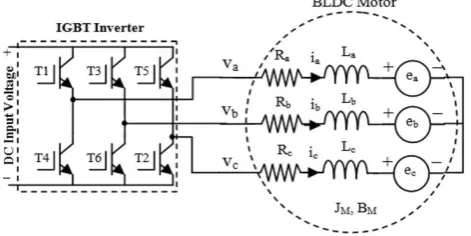
[image:1.595.307.543.294.412.2]The BRUSHLESS DC MOTOR has three stator windings and permanent magnets on the rotor.
Fig -1: Equivalent circuit of the BLDC servomotor drive system.
The circuit equations of three windings in phase variables are as follows,
…….(1)
Where it has been assumed that the stator resistances of all the windings are equal
Where,
ea, eb, ec:- a, b, and c phase back-EMF’S.
ia ,ib ,ic :- phase currents
R :-Stator winding resistance per phase
a c
c b
b a
c b a
t i
c b a
ca bc ab
e e
e e
e e
i i i
d d
M L M
L
L M M L
L M M L
i i i
R R
R R
R R V
0 0
0
0 0
0
© 2016, IRJET ISO 9001:2008 Certified Journal
Page 1408
L & m :-are self-inductance andmutual inductance per phase.
Since the mutual inductance is negligible as compared to self-inductance, equation 1 can be rewritten as,
……(2)
…….(3)
…….(4)
…….(5)
The relationship between the phase current is given by,
The equation is rewritten as,
…….(6)
Using Eq. 6 the line voltage Eq. 1 and 2 rewritten as,
…….(7)
…….(8)
The back emf depends on the flux of permanent magnet rotor and speed of the rotor, it is expressed as,
…….(9)
Where
=
Wm=Rotor speed, rad/sec
Ke=Back-emf constant, volts/rad/sec
The generated electromagnetic torque is given by,
…….(10)
The dynamics of motor and load is expressed as,
…….(11)
…….(12) …….(13) …….(14) a c c b b a c b a t i c b a ca bc ab e e e e e e i i i d d L L L L L L i i i R R R R R R V 0 0 0 0 0 0 V V b a b a t i b a
ab
i
i
e
e
d
d
L
i
i
R
V
(
)
(
)
c b c b t i c b
bc
i
i
e
e
d
d
L
i
i
R
V
(
)
(
)
a c a c t i a c
ca
i
i
e
e
d
d
L
i
i
R
V
(
)
(
)
0
b ca
i
i
i
)
(
a bc
i
i
i
b a b a t i b a
ab i i e e
d d L i i R
V ( ) ( )
c a b a t i b a
bc i i e e
d d L i i R
V ( 2 ) ( 2 )
) 3 4 ( ) 3 2 ( ) ( 2 e e e m e c b a F F F k e e e
c e e b e e a e e e i F K i F K i F K T 3 4 2 3 2 2 2
m Lm f e T dt d J K
T
m m f L e dt d J K TT
m Te TL Kf m dtd
J
e L
m f
m
T
T
© 2016, IRJET ISO 9001:2008 Certified Journal
Page 1409
WhereJ=Moment of inertia in kg/m2 Kf=Friction constant in Nm/rad/sec TL= Load torque in Nm
3. Speed control of BLDC motor
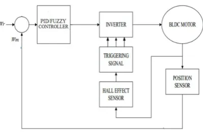
The complete block diagram for the speed control BLDC motor is shown in the fig 2. For controlling the BLDC motor two closed loops are used. In the inner loop the inverter gate signals are synchronized with the electromagnetic forces. By varying the DC bus voltage the outer loop controls the motor’s speed.
[image:3.595.309.517.120.241.2]Fig -2: Block diagram of speed control of BLDC motor The driving circuitry consists of inverter, which has six switches to energize two BLDC motor phases concurrently. The rotor position determines the switching sequence of the switches, is detected by the means of three hall sensors. Using the hall sensors information as well as the sign of reference current which is produced by the reference current generator the decoder block generates signal of back emf.
[image:3.595.43.243.312.442.2]TABLE -1: CLOCKWISE ROTATION
TABLE -2: GATE LOGIC
4. Controller circuit
4.1 PID controller
Proportional-integral-derivative controllers are being widely used in the industrial control systems as they require only few parameters to be tuned. The advantage is that the PID controllers have the capability of eliminating steady state error due to the integral action and can anticipate output changes due to the derivative action when the system is subjected to step reference input. Ziegler-Nichols method is widely used for PID tuning and it completely relies on the parameters obtained from the system step response.
Consider the characteristics parameters of proportional (P), integral (I), derivative (D) controls applied to the Fig 3.
Fig -3: Simulation model of PID controller
In the most basic form the transfer function of PID controller is,
C(s)= + S …….(1)
C(s)=
[image:3.595.312.513.473.608.2]© 2016, IRJET ISO 9001:2008 Certified Journal
Page 1410
= integral gain= derivative gain
The control u that is from the plant is equal to the proportional gain times the magnitude of error plus the integral gain times the integral of error plus the derivative gain times the derivative of error.
U= + …….(2)
Due to its simplicity PID controllers are used in about 95% of closed loop industrial processes.
We are mostly interested in the four major characteristics of closed loop step response. They are,
1) Rise time – The time taken by the plant output Y to rise beyond 90% of the desired level for the first time.
2) Overshoot – It is how much the peak level is higher than the steady state, normalized against the steady state.
3) Settling time – Time it takes for the system to converge to its steady state.
4) Steady-state error – It is the difference between the steady state output and the desired output.
Typical types for designing the PID controller,
i. Identify which characteristics of the system have to be improved.
ii. To decrease the rise time use .
iii. To reduce the overshoot and the settling time
use .
iv. To eliminate the steady state error use .
4.2 Fuzzy logic controller
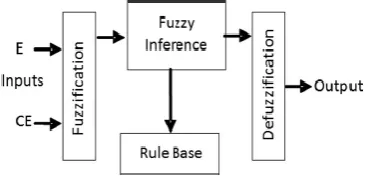
[image:4.595.324.509.111.202.2]The fuzzy logic control (FLC) is basically a control algorithm based on the linguistic control strategy which tries to account the human’s knowledge about how a system can be controlled without requiring mathematical model.
Fig -4: General Block Diagram of FLC
The input and outputs are the non-fuzzy values. Mamdani type of fuzzy logic is being used for speed control.
The general block diagram of the fuzzy logic controller is shown in fig. It consists of four parts.
1) Fuzzification- This process converts the measured input or the crisp values into the fuzzy linguistic variables. 2) Fuzzy rule base- A collection of the expert control rules
that are needed to achieve the control.
3) Fuzzy inference engine- Makes the rule work in response to the system input.
4) Defuzzification- This process is reverse of the fuzzification i.e. it converts the fuzzy reasoning mechanism into the required crisp value.
The fuzzy logic controller is designed as per the following steps.
i. Define input, output and universe of discourse. ii. Define fuzzy membership function and rules. iii. Defuzzification
The inputs are taken as error in speed and change in error in speed and the output is control signal for voltage generation. The fuzzy logic controller based system is designed using MATLAB toll for fuzzy inference system (fis).
The rules are being made by defining the fuzzy input variables ‘E’ and ‘CE’ which are quantized further. The fuzzy output variable is taken ‘ΔC’.
TABLE -3: The 3x3 fuzzy associated matrix
CE/E NE ZE PE
NCE D I I
NCE D NC I
[image:4.595.304.522.658.739.2]© 2016, IRJET ISO 9001:2008 Certified Journal
Page 1411
5. Simulation and discussion
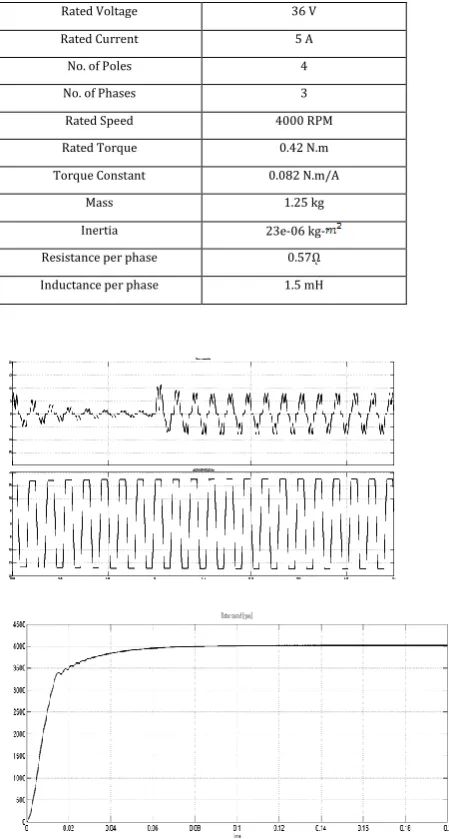
[image:5.595.329.556.70.362.2]To validate the control strategies, simulation was carried out on BLDC motor system by using MATLAB/SIMULINK. The motor parameters are given in the following table.
TABLE -4: Specification of motor
Rated Voltage 36 V
Rated Current 5 A
No. of Poles 4
No. of Phases 3
Rated Speed 4000 RPM
Rated Torque 0.42 N.m
Torque Constant 0.082 N.m/A
Mass 1.25 kg
Inertia 23e-06
kg-Resistance per phase 0.57ῼ
Inductance per phase 1.5 mH
Fig -5:
PID controllerFig -6: Fuzzy controller
Simulation has been carried with PID controller for Brushless (BLDC) DC motor with the load torque of 0.46Nm. Fig 5 shows the stator current and the back emf/electromotive force, as predicted the back emf/ electromotive force is trapezoidal. Fig 5 shows the speed response when the PID controller is used. It is evident that the motor speed settles down at the reference value of 4000rpm at 0.1 sec with little oscillations.
Fig 6 shows the waveform of stator current, back emf/ electromotive force and the speed response using fuzzy controller. The back emf/ electromotive force is trapezoidal in nature as predicted. It can be seen from speed response curve that the speed settles down with minimal oscillations at 0.02 secs.
6. CONCLUSIONS
[image:5.595.32.257.197.617.2]© 2016, IRJET ISO 9001:2008 Certified Journal
Page 1412
REFERENCES
[1] R.Shanmugasundram, K.Muhammad Zakariah, and
N.Yadaiah , “Implementation and Performance Analysis of Digital Controllers for Brushless DC Motor Drives”, IEEE Trans. Mechatronics, vol. 19, no. 1, February 2014.
[2] Muruganantham. N, Palani. S,“Hybrid Fuzzy-PI
controller based speed control for pmbldc motor using soft switching", European Journal of Scientific Research, June 2012.
[3] Muhammad Firdaus Zainal Abidin, Dahaman Ishak and
Anwar Hasni Abu Hassan, "A comparative study of PI, Fuzzy and Hybrid PI-Fuzzy controller for speed control of Brushless DC motor Drive"- IEEE International Conference on Computer Applications and Industrial Electronics, 2011.
[4] Amit Vilas Sant and K. R. Rajagopal, “PM Synchronous
Motor Speed Control Using Hybrid Fuzzy-PI With Novel
Switching Functions” IEEE transactions on
magnetics,vol.45, no.10, October 2009
[5] S. Srikant," Modeling and PID control of the brushless DC
Motor with the help of genetic algorithm," in IEEE-Inter. conference on Advances in Engg, Science and Mngt. 2012.
[6] R. Shanmugasundram, K. Zakariah Muhammad and
Yadaiah N., "Digital Implementation of Fuzzy Logic Controller for Wide Range Speed Control of Brushless DC Motor," in ICVES, 2009.
[7] B. Indu Rani, Ashly Mary Tom, “Dynamic Simulation of