© 2016, IRJET | Impact Factor value: 4.45 | ISO 9001:2008 Certified Journal | Page 198
Load Frequency Control – An ELC based approach
Ashwin Venkatraman
1, Paduru Kandarpa Sai
2, Mohit Gupta
31
Electrical Engineering Department, Indian Institute of Technology Jodhpur
2Electrical Engineering Department, Indian Institute of Technology Jodhpur
3Electrical Engineering Department, Indian Institute of Technology Jodhpur
---***---Abstract -
The aim of this study is to design an ElectronicLoad Controller (ELC) for a stand-alone micro-hydro generation network. In a stand-alone micro-grid, frequency control is a main concern. At any given instant, power balance in the system must be maintained by continuously matching the power supplied by the generators with the power consumed by the loads. In order to achieve Load Frequency Control (LFC) for the system, a dump load controlled by a frequency controller is used, which varies the dump load resistance based on the output of the controller. All simulations were carried out in MATLAB/Simulink environment.
Key Words: Load Frequency Control, Frequency
Regulators, Control Pulse Generator, Dump Load.
1. INTRODUCTION
Micro-grids powered by Renewable Energy Sources (RES) are becoming increasingly popular and are extensively studied due to their insignificant environmental impact compared to the classical power plants.
A stand-alone micro grid needs to be self-sufficient when it comes to power quality, especially regulation of voltage and frequency. Voltage variations are related to the reactive power of the system whereas frequency is related to the active power in the system. Thereby, to achieve frequency control, active power balance is essential.
To ensure a functional and reliable grid, the instantaneous frequency must be maintained very close to the original grid frequency (60 Hz or 50 Hz depending on the region). When the generation and demand are exactly matched, the grid frequency is held at a constant level.
In a practical power systems situation, the load, which actually is the consumer load, varies continuously,
thereby making some kind of control method a major necessity. Therefore, frequency control has been studied extensively in literature, with a wide variety of methods available for the same. Usually, it is achieved by controlling the mechanical power of the prime mover of generators. The efficiency of such a control strategy should be high as the generated power is maintained in range of the power demand. But, due to the mechanical constraints, the regulating process is slow and the overall cost is also significant. Moreover, the system response to sudden load changes is poor, thereby resulting in voltage sags and frequency deviations. [1]
But, for low power systems, such as micro-hydro generation system, the easier and cost-efficient way is to use ELC instead of controlling the mechanical side of the generator. The operating principle of such an ELC is that it the total generated power equals the sum of power consumed by consumer’s loads and the ELC. As active power balance is achieved, frequency is satisfactorily regulated. Moreover, this energy can be transformed into other forms of energy [1-3] such as heat, or can be stored for usage during periods of lack of energy.
© 2016, IRJET | Impact Factor value: 4.45 | ISO 9001:2008 Certified Journal | Page 199
2. SYSTEM DESCRIPTION
The power source in this system is a micro-hydro generator, whose Simulink model is given in Fig 2. The Synchronous generator is 100kVA/480 V and 60 Hz and is driven by a Hydraulic turbine system. The Hydraulic Turbine System implements a hydraulic turbine combined to a PID governor system and the excitation system acts as the voltage regulator combined with an exciter. The generator supplies both the consumer load as well as the dump load. The consumer load is modelled using two constant 3 phase resistive loads with a breaker connected to one of them to simulate the load variations. A fixed value terminal capacitor is added in order to result in rated terminal voltage at full load. The output power of the generator must be held constant at all consumer loads as any decrease in the consumer load may accelerate the machine and raise the voltage and frequency levels over the tolerable limit, which in case of frequency is usually +- 0.5 Hz. This would also result in increased stress on other loads. The excess power is hence supplied to the dump load through the controller so that Pg = Pc + Pdl wherePg is generated power, Pc is the power consumed by the consumer load and Pdl is the power consumed by the dump load.
The frequency controller is used to generate control pulses, which is then fed as input to the dump load. The dump load resistance is then varied depending on the value of the pulses generated.
3. CONTROL STATEGY
The Simulink model of the load part of the system is shown in Fig 3. It consists of a 3 phase resistive load of 60 kW rating, which is the main load, and a 3 phase resistive load of 10 kW rating that is connected in series with a 3 phase breaker, which is used to simulate the variation in consumer load. The control system consists of two blocks. The first one is a control pulse generator, which generates a total of 24 pulses, 8 per each phase. It consists of a 3 phase PLL, which measures the frequency. It is then compared with the reference frequency of 60 Hz and the resultant error signal is passed through an integrator in order to get the phase error. The phase error is then passed through a PID controller and thereafter, the resultant output is converted into 8 bit output.
This is then used to generate a 24 bit output (8 per each phase). In order to reduce switching losses and other related voltage disturbances, Zero-Voltage Switching (ZVS) is used.
The other block in the control system is that of the dump load. It takes a stream of 8 bits as input and based on the values of the bits, the resistance is varied in 256 different levels. The dump load resistance was chosen as 100 kW and it was varied from 0 to 100kW in steps of 0.4 kW each.
[image:2.595.330.522.245.386.2]In order to further reduce the harmonics generated, harmonic filter block available in Simulink was used in the load side.
Fig -1: Overall System Diagram
[image:2.595.313.548.463.644.2]© 2016, IRJET | Impact Factor value: 4.45 | ISO 9001:2008 Certified Journal | Page 200
Fig -3: Simulink Model of Consumer Load and Dump Load4. SIMULATION RESULTS AND DISCUSSIONS
All simulations were carried out in MATLAB/Simulink. The synchronous generator was rated 100kVA, 480 V and 60 Hz, salient pole machine with 2 pole pairs. The breaker used to simulate the variations in the consumer load was initially open with transition times 0.5 s, 1 s, 1.5 s and 2 s.
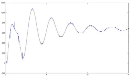
Fig 4 shows the frequency of the system for the simulation time of 15 s. The initial variation in the frequency is within the accepted norm of 0.5 Hz. It is observer that the steady state value of frequency is 60 Hz, thereby verifying that the proposed control method is successful.
Fig 5 and 6 presents the various power measurements, namely generated power, power consumed by the consumer load and power consumed by the dump load. It is observed from the graphs that the power expression mentioned earlier is valid.
Fig 7 presents the voltage and current measured at the generator.
Fig 8 shows the harmonics calculation done on the source voltage, which comes out to be 2.16%.
Fig 9 shows the voltage and current measured at the consumer load whereas
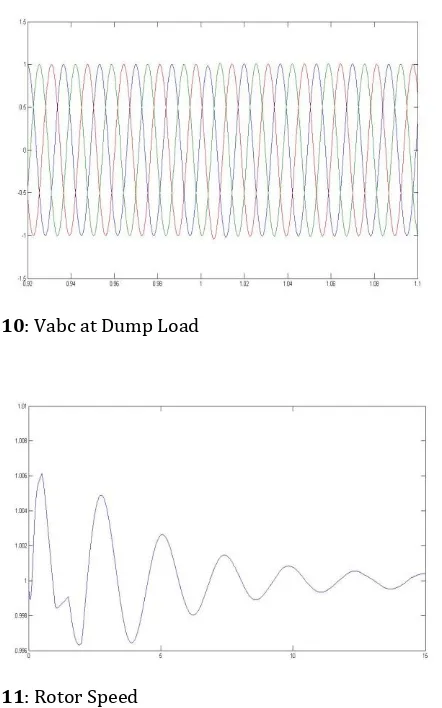
Fig 10 shows the voltage measured at the dump load.
Fig 11 shows the rotor speed of the synchronous generator.
Fig -4: Frequency
Fig -5: Generated Power
© 2016, IRJET | Impact Factor value: 4.45 | ISO 9001:2008 Certified Journal | Page 201
Fig -6b: Power Consumed by Dump LoadFig -7a: Vabc Generated
Fig -7b: Iabc Generated
[image:4.595.334.546.314.448.2]Fig -8: Total Harmonic Distortion
Fig -9a: Vabc at Main Load
[image:4.595.63.274.318.439.2]© 2016, IRJET | Impact Factor value: 4.45 | ISO 9001:2008 Certified Journal | Page 202
Fig -10: Vabc at Dump LoadFig -11: Rotor Speed
5. CONCLUSIONS
Frequency control in a stand-alone micro-grid system was studied. An ELC was designed and developed in
MATLAB/Simulink environment. From the simulated results, it can be concluded that the developed ELC for the system maintains the voltage and the frequency at a constant value despite variations in the consumer load.
Moreover, the Total Harmonic Distortion (THD) of ELC is 2.16%, thereby exhibiting a satisfactory performance. Hence, the proposed system can be used in micro-hydro applications in remote locations/hilly areas.
\
ACKNOWLWDGEMENT
We would like to take this opportunity to express our deep sense of gratitude and profound feeling of admiration to our supervisor Dr. Abdul Gafoor Shaik.
REFERENCES
[1] I. Şerban, C.P. Ion, C. Marinescu, Frequency Control and
Unbalances Compensation in Autonomous Micro-Grids Supplied by RES, The IEEE International Electric Machines and Drives Conference, CD Proceedings, Turkey, May 2007.
[2] R. Sebastian, J. Quesada, Distributed Control System for
Frequency Control in a Isolated Wind System, Science-Direct – Renewable Energy, 31, 3, pp. 285–305 (2006).
[3] I. Şerban, C. Ion, C. Marinescu, M. N. Cîrstea, Electronic
Load Controller for Stand-Alone Generating Units with Renewable Energy Sources, The 32nd annual conference of the IEEE Industrial Electronics Society – IECON 06, Paris, France, 2006, pp. 4309–4312.
[4] C.S. Chang, W. Fu Area load-frequency control using fuzzy
gain scheduling of PI controllers Electr. Power Syst. Res,
42 (1997), pp. 145–152
[5] Z.M. Ai-Hamouz, Y.L. Abdel-Magid Variable-structure load-frequency controllers for multi area power systems
Int. J. Electr. Power Energy Syst, 15 (5) (1993), pp. 23– 29
[6] M.Deb , A.Das , G.Deb, Control of Voltage and Frequency of a Wind Electrical System using Frequency Regulator,
International Journal of Engineering Research & Technology (IJERT) Vol. 3 Issue 3, March – 2014.
[7] Juan M. Ramirez, Emmanuel Torres M, An Electronic Load Controller for Self-Excited Induction Generators. [8] I. Şerban, C. Marinescu Power Quality Issues In A
Stand-Alone Microgrid Based On Renewable Energy, Revue