© 2017, IRJET | Impact Factor value: 6.171 | ISO 9001:2008 Certified Journal | Page 1146
COMPARATIVE STUDY OF CONCRETE PRISMS CONFINED WITH G-FRP
WRAPPING UNDER COMPRESSIVE LOADING
VISHNUVARDAN NARAYANAMURTHI
Assistant Professor, Department of Civil Engineering,
Sri Muthukumaran Institute of Technology, Chikkarayapuram, Chennai 600069
---***--- Abstract - The strength of confined columns is higher for
circular section due to stress concentration at corner. To expand the strong constraint zone and diminish the stress concentration the sharp edge can be done rounded and chamfered. Fiber Reinforced Polymer (FRP) materials are composites consisting of high strength fibers embedded in polyester resin. Fiber in on FRP composites are the load carrying elements, while the resin maintains the fiber alignment and protects them against the environment and possible damage. Among fibers, glass one exhibit the highest strength and stiffness when compared with steel Present paper deals with experimental results in terms of load carrying capacity and stress – strains behavior of fiber reinforced polymer (FRP) confined prism. The ultimate stress of prism with corner radius of 13mm and 19mm is 1.06 and 1.12 times more than the sharp edge prism. Similarly the failure strain is 3.6 and 1.31 times more than the sharp edge prism. The ultimate stress of prism with chamfered corner of 13mm and 19mm is 1.12 and 1.31 times more than the sharp edge prism. Similarly the failure strain is 1.12 and 1.31 times more than the sharp edge prism. The stress-strain curve behaves bilinear and the stress-strain curve traces the same path as that of unconfined concrete until the jacket was activated. The FRP resists lateral deformation results in a confining stress to the concrete core thereby delaying the rupture and enhancing both the ultimate strength and stain of the concrete.
Key words: GFRP, Chamfered prism, compressive test, confinement, Woven Glass fiber, stress strain.
1.INTRODUCTION
According to the ACI 440R-96 report, the term “composite” can be applied to any combination of two or more separate materials having a distinguishable interface between them. Often a surface treatment phase is introduced between the two combining materials, which improve the adhesion of the reinforcing component to the matrix phase. When composites are defined as polymeric matrix reinforced with fibers, they are called as fiber reinforced polymers (FRP). Advantages of FRP are High chemical resistance to acids and bases, reduction of corrosion related problems, practically no increase of dead weight of the structure, Economically use in many cases and Significant use in repair and
© 2017, IRJET | Impact Factor value: 6.171 | ISO 9001:2008 Certified Journal | Page 1147
columns Silva (2011). the Glass fiber wrapped specimens typically failed by a fracture of GFRP composite at or near the corner of the specimens due to the stress concentration in those regions Raid Benzaid and Nasr-Eddine Chikh (2008).
2. OBJECTIVE
Objective is to study Stress-strain relationship, Ultimate compressive strength and failure strain of FRP confined square concrete prisms by varying edges as corner radius, chamfered and sharp.
3. PROPERTIES OF MATERIAL
Cement used for making prisms is OPC 53 grade (Bharathi cement) was used for the entire experimental investigations. The physical properties of the above tested according to standard procedure, conforms to the requirements of IS 12269-1989. The properties are as follow: fineness of 0.8%, specific gravity 3.85, consistency 34% of weight of cement. The fine aggregate used in this study are clean river sand,
passing through 4.75mm sieveFine aggregate have fineness
of 3.12, specific gravity 2.86, bulk density 1608 kg/m3, water
absorption 1% and grading for zone II. Machine crushed stone with angular shape was used as coarse aggregate. The minimum and maximum size of aggregate is 12.5mm and
20mm respectivelyCoarse aggregate have fineness of 8.08,
specific gravity 3.1, bulk density 1616 kg/m3, water
absorption 0.5%, maximum size of 20 mm and angular in shape. Ordinary clean potable water free from suspended particles was both for mixing of concrete and curing. E-Glass FRP (Woven Mat) is used in the experiment. E-glass is the most common type of glass fiber used in resin matrix composite structures and was used in this investigation. The principal advantages of E-glass are low cost, high tensile and
impact strength and high chemical resistance. The
disadvantages of E-glass, compared to other structural fibers are lower modulus, lower fatigue resistance and higher fiber self- abrasion characteristics. In general, fiber composites
behave linearly elastics to failure
.
GFRP and resin used havetensile strength of 1750 and 2500 N/mm2, Elastic modulus
65 and 74 x103 N/mm2, thickness 2.6 and 1.8 mm, poison
ratio 0.23 and 0.29 respectively.
4. SPECIMEN DETAILS AND CASTING
In the present investigation, total 15 no. which were divided into two sets as with and without wrapping of roved with
E-Glass FRP of Woven Mat(3 in each category). of concrete
prisms will be casted and be tested under compressive loading; the types of the specimen are square prism 150 x 150 x 300 mm with sharp edges, square prism with corner radius of 19 mm and 13 mm and square prism with
chamfered edge of 19 mm and 13 mm as shown in figure 1. M30 mix design is adopted for the study. Ratio is 1:2:3.7 with
0.45 w/c ratio and 380kg/m3 of cement. The specimen
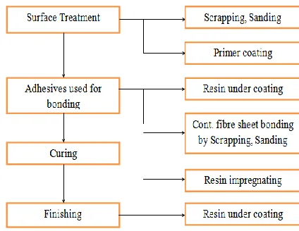
[image:2.612.324.569.246.379.2]preparation work can be divided into two stages: making concrete prisms and hand-apply the GFRP around these prisms. The prisms were cast in vertical position. First mould was filled to about the half height and then compacted using damping rod. The mould was filled in three layers in the same manner. The FRP bonding procedure was done in accordance to ACI 440.2R-02. The entire installation procedure consists of three major phases. They are Surface preparation, Fabric preparation and Fabric installation. The process flow chart is shown in figure 2.
Fig - 1. Chamfer and Corner Radius detailing
Fig - 2. Steps of FRP wrapping over prism
5. TESTING OF SPECIMEN
[image:2.612.338.550.415.579.2]© 2017, IRJET | Impact Factor value: 6.171 | ISO 9001:2008 Certified Journal | Page 1148
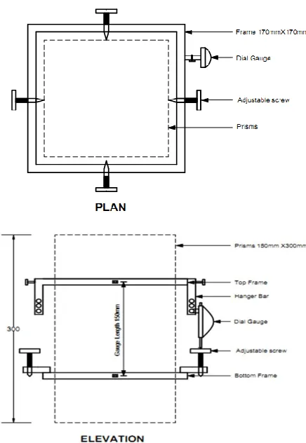
[image:3.612.83.253.160.276.2]square frames at top of the prism. The deformation indicated by the dial gauge divided by the gauge length of 150 mm gives strain at that level. From the load, corresponding stresses were calculated. The test was continued until specimens fails completely and from recorded reading, stress-strain values were plotted.
Fig - 3. Speciment in compression testing machine
Fig - 4. Straing gauge with steel frame setup
6. RESULTS AND DISCUSSIONS
Results show a significant improvement of load carrying capacity and failure strain with the use of FRP confinement. Stress–strain curves, which characterize the confined
[image:3.612.56.274.310.626.2]concrete, are bilinear whatever the strength of the concrete core. This study reveals a significant change of behaviour when the concrete is confined. The tests proved that the benefits of confinement could be enhanced by the use of FRP confinement, which can be seen from the results of testing the compressive loading prisms. The failure mode for FRP- confined concrete is the rupture of the FRP jacket due to hoop tension and FRP delaminating. The breakage line was generally perpendicular to the fibers. For whatever sharp edge, chamfered edge, corner radius, the breakage line appeared at a corner, specifically in corner radius exactly at the end of the rounding. The failure of all of the confined square columns took place at one of the corners within the mid-height of the specimen as shown in figure 5. The stress strain graph of comparing sharp edge with all other prisms are shown in chart 1, 2, 3 and 4 correspondingly.
Fig - 5. Failure crack of concrete prisms
Chart - 1. Stress-Strain curve Comparing Sharp edge prism without wrapping and FRP wrapped prism with corner
radius 19mm
0 10 20 30 40 50 60
0.000 0.003 0.006 0.009 0.012 0.015 0.018 0.021
ST
R
ES
S
(N
/m
m
2)
STRAIN
Stress-Strain curve
Comparing Sharp edge prism without wrapping and FRP wrapped prism with corner radius 19mm
Sharp Edged prism without FRP wrapping
[image:3.612.316.573.368.672.2]© 2017, IRJET | Impact Factor value: 6.171 | ISO 9001:2008 Certified Journal | Page 1149 Chart - 2. Stress-Strain curve Comparing Sharp edge prism
without wrapping and FRP wrapped prism with corner radius 13mm
Chart - 3: Stress-Strain curve Comparing Sharp edge prism without wrapping and FRP wrapped prism with Chamfer
13mm
Chart - 4: Stress-Strain curve Comparing Sharp edge prism without wrapping and FRP wrapped prism with Chamfer
19mm
7. CONCLUSION
The provision of FRP is an effective way of providing additional confinement of concrete. The external confinement with Fiber reinforced polymer composites can significantly increase the strength of the specimen under compressive loading. From the experimental results, while comparing the ultimate stress between sharp edge and corner radius of 13mm wrapped with Woven Roving Mat G-FRP, the ultimate stress in corner radius increases 1.06 times than the sharp edge prism. Similarly while comparing the failure strain, corner radius prism increases 3.6 times than the sharp edge prism For the ultimate stress between sharp edge and corner radius of 19mm wrapped with Woven Roving Mat G-FRP, the ultimate stress in corner radius increases 1.12 times than the sharp edge prism. Similarly the failure strain in the corner radius increases 1.31 times than the sharp edge prism. For the ultimate stress between sharp edge and chamfered edge of 13mm wrapped with Woven Roving Mat G-FRP, the ultimate stress in corner radius increases 1.12 times than the sharp edge prism. Similarly the failure strain in the corner radius increases 1.31 times than the sharp edge prism. For the ultimate stress between sharp edge and chamfered edge of 19mm wrapped with Woven Roving Mat G-FRP, the ultimate stress in corner radius increases 1.12 times than the sharp edge prism. Similarly the failure strain in the corner radius increases 1.31 times than the sharp edge prism. The stress-strain curve for concrete confined by FRP composites behaves bilinear and the
stress-0 5 10 15 20 25 30 35 40 45 50
0.000 0.003 0.006 0.009 0.012 0.015
ST
R
ES
S
(N
/m
m
2)
STRAIN Stress-Strain curve
Comparing Sharp edge prism without wrapping and FRP wrapped prism with corner radius 13mm
Sharp Edged prism without FRP wrapping
FRP wrapped prism with corner radius 13mm
0 5 10 15 20 25 30 35 40 45
0.000 0.003 0.006 0.009 0.012
ST
R
ES
S
(N
/m
m
2)
STRAIN Stress-Strain curve
Comparing Sharp edge prism without wrapping and FRP wrapped prism with Chamfer 13mm
Sharp Edged prism without FRP wrapping
FRP wrapped prism with chamfer 13mm
0 5 10 15 20 25 30 35 40 45 50
0.000 0.003 0.006 0.009 0.012 0.015
S
T
R
E
S
S
(
N
/m
m
2)
STRAIN Stress-Strain curve
Comparing Sharp edge prism without wrapping and FRP wrapped prism with Chamfer 19mm
Sharp Edged prism without FRP wrapping
© 2017, IRJET | Impact Factor value: 6.171 | ISO 9001:2008 Certified Journal | Page 1150
strain curve traces the same path as that of unconfined concrete until the jacket was activated. The failure of the square columns always starts at one of the corners proving that the stress concentration occurs at the corners The FRP resists lateral deformation due to the compressive load and results in a confining stress to the concrete core thereby delaying the rupture of concrete and enhancing both the ultimate compressive strength and the ultimate compressive stain of the concrete.
8. SCOPE OF FUTURE STUDY
The stress-strain behaviour of plain concrete prisms with different types of laterals should be studied. The stress-strain behaviour of FRP confined concrete externally strengthened with high strength fibre composite wraps of
CFRP and epoxy resin should be studied. A systematic study
is required to understand the effects of adverse environmental condition (humidity, freezing and thawing) on the deflection and ultimate load carrying capacity of the FRP confined concrete. The effectiveness of various types of corner radius of reinforced columns externally strengthened with CFRP and GFRP should be studied. Case study on the lateral and axial strain behaviour of FRP confined concrete for eccentric and cyclic loading may also be attempted. An analytical model can be made to determine the maximum bearing capacity of concrete members with different cross sections for different configurations.
REFERENCES
[1]. ACI Committee 440 (1996), State-of-the-Art Report
on Fibre Reinforced Plastic (FRP) for Concrete Structures (ACI 440R). ACI Manual of Concrete Practice, Part 5, American Concrete Institute, Detroit, MI, 68 pp.
[2]. Emmons, P. H., Vaysburd, A. M. and Thomas, J.
(1998), Strengthening Concrete Structures, Part I, Concrete International, V. 20, No. 3, pp. 53-58
[3]. Emmons, P. H., Vaysburd, A. M. and Thomas, J.
(1998), Strengthening Concrete Structures, Part II, Concrete International, V. 20, No. 4, pp. 56-60.
[4]. Karbhari, V. M. (2001), Materials Considerations in
FRP Rehabilitation of Concrete Structures, Journal of Materials in Civil Engineering, V. 13, No. 2, pp. 90-97.
[5]. Mirmiran.A and Shahawy. M, Behaviour of Concrete
Columns Confined by Fibre Composites, Journal of Structural Engineering, Vol.123, No.5, May 1997, pp: 583-590.
[6]. Mirmiran.A and Shahawy. M, Samaan M., Echary
H.E., Mastrapa J C., Pico O., Effect of Column Parameters on FRPConfined Concrete, Journal of composite for Construction, Vol.2, No.4, Nov 1998, pp: 175-185.
[7]. Omar Chaallal, Mohsen Shahawy and Munzer Hassan
(2003), Performance of Axially Loaded Short Rectangular Columns Strengthened with Carbon Fiber-Reinforced Polymer Wrapping. Journal of composite for construction. vol.7, No.3, pp.200-208.
[8]. Riad Benzaid, Nasr-Eddine Chikh and Habib Mesbah.
(2009), Study of the compressive Behaviour of short concrete column confined by fibre reinforced composite, The Arabian Journal for science and engineering .vol.34, No.1B, pp.15-26
[9]. Stephen Pessiki, Kent A. Harries, Justin T. Kestner,
Richard Sause, James M. Ricles (2001), Axial Behavior of Reinforced Concrete columns confined with FRP jackets Journal of composites for construction November 2001 / 237
[10]. Tamuzs.V, Valdmanis.V, Gylltoft.K, and Tepfers.R
(2007), Behaviour of CFRP-confined concrete Cylinders with a Compressive Steel Reinforcement, Mechanics of Composite Materials, Vol. 43, No. 3, 2007.
[11]. Theodoros C. Rousakis and Athanasios I. Karabinis
(2008) Behaviour of concrete confined by high E-modulus Carbon FRP sheets subjected to monotonic and cyclic axial compressive load, Journal of materials and structures (2008)41:1595-1611
[12]. Xiao.Y and Wu.H (2000) Compressive Behavior of
concrete confined by Carbon Fiber Composite Jackets, Journal of composite for construction, Vol.7, No.3, pp.200-208.
[13]. Yu-Fei Wu and You-Yi Wei (2010) Effect of