THE STUDY OF 2 DIFFERENT
AUTOMOTIVE SPRAYING TECHNIQUES MODELED
WITH REFERENCE TO 2 DIFFERENT SPRAY ANGLE
YEOH POH SEE
A project report submitted in partial
fulfillment of the requirement for the award of the
Degree of Master of Mechanical Engineering
Faculty Of Mechanical And Manufacturing Engineering Universiti Tun Hussein Onn Malaysia
ABSTRACT
Conventional automotive spray gun is widely used in the automotive industries for coating and is especially popular among small and medium industries due to its low cost and maintenance. However studies showed that it also causes overspray of paint that affect the hygiene factor concerning health and less cost effective when usage of spray is not properly utilized. Various methods have been used to study the efficiency of the spray through simulation software and lab approach. In this work, the simulations of the spray paint are performed from the air cap of the spray gun and continue until the flat spray surface. The simulations are performed using ANSYS CFX Version 14.5 based on the Taguchi method. The Taguchi method used in this study implemented the L’9 orthogonal array, since this case study consists of 3 level and 3 factor. This simulation utilize paint as a non-Newtonian fluid taking into
consideration the concentration of paint as the additional variable in [kg/m3], air
ABSTRAK
Conventional automotive spray gun banyak digunakan dalam industry automotif untuk tujuan penyalutan dan ianya amat popular dikalangan industry kecil dan
sederhana (SME) kerana harganya yang jauh lebih murah berbanding spray lain.
Selain daripada itu penyelenggaraan spray juga mudah menjadikan ianya pilihan
SME. Walau bagaimanapun, kajian mendapati bahawa spray jenis ini menyebabkan
lebihan semburan dalam proses penggunaannya. Lebihan semburan ini bukan sahaja memudaratkan kesihatan malah mendatangkan kerugian kerana menyebabkan banyak sisa buangan bahan semburan. Pelbagai kaedah telah digunakan dalam kajian sebelum ini untuk mengkaji kecekapan spray dengan menggunakan perisian simulasi dan kaedah eksperimentasi. Dalam kajian ini, simulasi penyemburan car dilaksanakan menggunakan perisian ANSYS CFX versi 14.5 berdasarkan kaedah
Taguchi. Kaedah Taguchi dengan orthogonal array L’9 diimplementasikan kerana
kajian kes ini melibatkan 3 peringkat dan 3 faktor. Simulasi menggunakan cat sebagai cecair bukan Newtonian dngan mengambilkira penumpuan cat sebgai
pemboleubah tambahan dalam unit [kg/m3], halaju udada di masukan atomizer,
CONTENT
TITLE i
DECLARATION ii
DEDICATION iii
ACKNOWLEDGEMENT iv
ABSTRACT v
ABSTRAK vi
CONTENTS vii
LIST OF TABLES xi
LIST OF FIGURES xii
LIST OF SYMBOLS xiv
LIST OF APPENDICES xv
CHAPTER 1: INTRODUCTION
1.1 Introduction 1
1.2 Problem Statement 2
1.3 Significance of study 3
1.4 Objective and scope of study 3
CHAPTER 2 : LITERITURE REVIEW
2.1 Automotive Paint Spray 5
2.1.1 Conventional Air Spray 6
2.1.1.2 Versatility 6 2.1.2 High-Volume Low-Pressure Atomization
(HPLV) 10
2.1.3 Airless Atomization 12
2.1.4 Air-assisted Airless Atomization 14
2.1.5 Electrostatic Atomization 15
2.2 Paint Composition and Characteristics 16
2.2.1 Component 17
2.2.1.1 Pigment and Filler 18
2.2.1.1.1 Pigment 18
2.2.1.1.2 Filler 18
2.2.1.2 Binder (Resin) 18
2.2.1.3 Diluent or Solvent 20
2.2.1.4 Additives 20
2.2.2 Application 21
2.2.2.1 Solid 21
2.2.2.2 Gas 21
2.2.2.3 Fluid 22
2.2.3 Techniques 22
2.2.3.1 Practical 22
2.2.3.2 Artistic 23
2.3 Characteristic of Automotive Paint 23
2.3.1 One or Two-Part 23
2.3.2 Single –stage or Basecoat/Clear coat 24
2.4 Spray Painting 25
2.4.1 Process (Siphon feed) 25
2.4.2 Painting Technique 26
2.5 Computational Fluid Dynamics Software 27
2.6 Benefits of CFD software 28
2.7 CFD Process 29
2.7.1 Preprocessing 29
2.7.2 Solver 29
2.7.3 Post processing 28
2.9 Design of experiment 34 2.9.1 Full factorial method 35 2.9.2 Advantages and Disadvantages
Full factorial method 36
2.10 Design of experiment via Taguchi method 37
2.10.1 General step for Taguchi method 38
2.10.2 Types of Orthogonal Array 38
2.10.3 Advantages and disadvantages
Taguchi method 39
2.11 Determining Parameter Design Orthogonal Array 39
2.12 Summary 41
CHAPTER 3: METHODOLOGY
3.1 Introduction 42
3.2 Methodology Flow Chart 43
3.3 Computational Modeling Using Autodesk
Inventor 3D Computer Aided Design (CAD) 44
3.4 Computational Modeling Of Conventional Paint
Spray Air Cap 44
3.5 Parameter of Conventional Paint Spray Air Cap 45
3.6 Simulation using ANSYS Software 46
3.6.1 Meshing 46
3.6.2 Preprocessor 48
3.6.3 Solver 51
3.6.4 Post processer 51
3.7 Parameter selection 52
3.8 Orthogonal Array 52
3.9 Grid Independency test 54
CHAPTER 4: RESULT AND DISCUSSION
4.1 Introduction 55
4.2 Grid Independence Test 55
4.3 Simulation of particle distribution using
Taguchi Method 56
1.3.1 Simulation No.3, No.5 and No.7 for Spray
Gun Perpendicular to Spray Surface Area
From a distance of 250 mm 60
1.3.2 Simulation No.2, No.4 and No.8 for Spray
Gun Perpendicular to Spray Surface Area
From a distance of 225 mm 62
1.3.3 Simulation No.1, No.6 and No.9 for Spray
Gun Perpendicular to Spray Surface Area
From a distance of 200 mm 64
1.3.4 Simulation No.3, No.5 and No.7 for Spray
Gun Arced 45 degrees to Spray Surface Area
From a distance of 250 mm 67
1.3.5 Simulation No.2, No.4 and No.8 for Spray
Gun Arced 45 degrees to Spray Surface Area
From a distance of 250 mm 68
1.3.6 Simulation No.1, No.6 and No.9for Spray
Gun Arced 45 degrees to Spray Surface Area
From a distance of 250 mm 69
4.4 Summary 70
CHAPTER 5: CONCLUSION AND RECOMENDATION
5.1 Conclusion 72
5.2 Simulation using Taguchi method 72
5.3 Recommendation 73
LIST OF TABLE
Table 2.1 Range of Pressure and Gun Nozzle Sizes
for Spraying Common Coating Material 8
Table 2.2 Parameter for Example 36
Table 2.3 Test Matrix 36
Table 2.4 Advantages And Disadvantages Of Full Factorial Method 36
Table 2.5 Advantages And Disadvantages Of Taguchi Method 39
Table 2.6 Spindle Speed 40
Table 2.7 Selector Array 40
Table 2.8 L’9 Array Select 40
Table 2.9 L’9 Array Table of Experiment 41
Table 3.1 Parameter for Conventional Paint Spray Air Cap 46
Table 3.2 Meshing Parameter 47
Table 3.3 Setting The Initial Comparison Properties For
The Conventional Paint Spray Air Cap. 50
Table 3.4 Setting The Properties For The Conventional
Paint Spray Air Cap. 51
Table 3.5 Parameter for Conventional Paint Spray Air Cap. 52
Table 3.6 L’9 Array Select 52
Table 3.7 Orthogonal array L’9. 53
Table 4.1 Different grid size with number of elements and nodes. 56
Table 4.2 Results for Simulation 3, 5 and 7. . 62
Table 4.3 Results for Simulation 2, 4 and 8. . 64
Table 4.4 Results for Simulation 1, 6 and 9. . 66
Table 4.5 Results for Simulation 3, 5 and 7. . 67
Table 4.6 Results for Simulation 2, 4 and 8. . 68
LIST OF FIGURE
Figure 2.1 Parts of a Typical Air Spray Gun . 7
Figure 2.2 Cross-sectional Diagram of an External Mix Spray Gun. 9
Figure 2.3 Cross-sectional Diagram of an Internal Mix Spray Gun 10
Figure 2.4 Typical Air Atomization Spray System 12
Figure 2.5 Typical Airless Atomization Spray System 14
Figure 2.6 Spray Painting Technique 27
Figure 2.7 A Table Fan Rotating Machinery Analysis Using
the Solid Works Flow Simulation CFD Solution 28
Figure 2.8 Reynolds Number. 32
Figure 2.9 Laminar and turbulent flow. 33
Figure 2.10 Example of Level and factor. 35
Figure 3.1 Flow chart of the process for this study. 43
Figure 3.2 Air Cap of a Conventional Paint Spray. 44
Figure 3.3 Conventional Flat Fan External Mixture
Spray Gun’s Air Cap 45
Figure 3.4 Dimension for Conventional Paint Spray. Air Cap 46
Figure 3.5 Before sizing the meshing. 48
Figure 3.6 After sizing the meshing. 48
Figure 3.7 Setting boundaries. 49
Spray perpendicular. 57
Figure 4.2 Eddy Viscosity of (a) Simulated Water and (b) Paint Spray;
Spray Arced 45 degrees 58
Figure 4.3 (a) Concentration of Simulated Paint, (b) Eddy Viscosity of Paint
Spray, (c) Concentration of Simulated Water and (b) Eddy Viscosity
LIST OF SYMBOL
CFD - Computational Fluid Dynamics
Re - Reynold Number
ρ - Density, kg/m³
µ - Dynamic Viscosity, kg/(m*s)
ν - Kinematic Viscosity, m²/s
V - Average Velocity, m/s
D - Diameter, m
3D - 3 Dimension
CHAPTER 1
INTRODUCTION
1.1 Introduction
Existing Small and Medium Enterprises (SME) in the vicinity of Ipoh, Perak [1] uses conventional automotive spray gun, which is a manual process. These guns develop excessive spray dust and overspray fog [2]. Many spray gun manufacturers suggested that the proper technique for spray gun stroke is with a free arm motion. The paint operators are to keep the gun at a right angle to the surface at all points of the stroke [3]. The Department of Skills Development Ministry of Human Resources, Malaysia; in its report Occupational Analysis Automotive Industry 2012 reported that for a paint operator to carry out this task, he has to be at least a Level 2: Paint Shop Senior Operator; or higher [4]. The Paint Shop Senior Operator’s job scope includes spraying the automotive paint.
Unfortunately, many automotive paint operators out there who are skilful, but are not aware of the need to record their techniques for referral use. They are not aware that their ‘tried and error’ sort of solution could actually turn out to be a management method to overcome losses or even generate profit.
protection or prevention taken and it is known as an Occupational Health and Symptoms Sick Building Syndrome [5].
Researches and spray gun manufacturers showed that a spray gun arced at angle 45 degrees from the surface will result in uneven application and excessive overspray at each end of its stroke. In other words, approximately 65% - 70% of the sprayed material is lost.
Studies need to be conducted on spraying techniques modelled with reference to these two suggested different spray angles. In the modern world of technology, there is software that can examine and give an overview on the subject. In addition to that, the results from these experiments can be compared against variable rate difference. Calculations and experiments carried out using a computer to simulate dispersion of paint in the air. This is done based on the specified settings of boundary conditions.
Fluid dynamics is a field of science that studies the physical laws governing the flow of fluid under various conditions. In this study, Computational Fluid Dynamics software, better known as CFD has been used to study the air and particle flow in a pipe and then at the exit blow head. CFD is software that makes the prediction of fluid flow by means of mathematical modelling (partial differential equations), numerical methods (discretization and solution technique) and software tools, namely (pre-processing, solver and post processing). Additionally, CFD can also help scientists and engineer for carry out experiments in a ‘virtual flow laboratory’.
Continuous research will improve the efficiency of the design in terms of the geometry of paint spray and airflow.
1.2 Problem statement
all points of the stroke and conventional spray gun arced at angle 45 degrees from the surface. The predicted result will be uneven application and excessive overspray as suggested by manufacturers of conventional spray gun. In other words, approximately 65% - 70% of the sprayed material is lost with reference to subjected spray area. This study use ANSYS CFX to model the spray pattern and will have to go through three stages, which is pre-processing, solver and post-processing to achieve the result.
1.3 Significance of study
This study can be obtained as a result of various designs of spray paint process with an effective and cost effective research. The success of this study will be beneficial to the automotive spray-painting sector to achieve uniformity in the distribution of paint and subsequently reduce wastage. In addition, it can help other researchers who study the hygiene factor effecting spray operator health and environmental affect. Besides, using software that has been developed, it can help or advice for the best solution to achieved the goal of the experiment.
By incorporating software in the study result in cutting of time and thus cost of the study. It also helps to eliminate unnecessary experiment that may cause hazard to living beings. Furthermore, various design of paint spray process can be made and later suggested to help other researcher to find the best and most effective design.
1.4 Objective and scope of study
The objectives of this study are to:
1. Simulate the spray pattern of the paint spray, angled at; arced 45 degrees
from the surface
2. Simulate the spray pattern of the paint spray; perpendicular to a flat surface
3. To suggest and improve the minimizing of overspray by suggesting the
To avoid diverted research objectives, some scope of study was created to be guidelines to achieve the above objectives:
1. Using Computational Fluid Dynamics (CFD) simulation software by
ANSYS; ANSYS CFX Version 14.5.
2. The fluid studied is automotive paint, with initial simulation based on water
in air at 25°C.
3. Simulated based on a non-controlled environment i.e. without a paint spray
booth; but in an open ground floor of a double storey intermediate shop lot size 20 x 85 sq. ft.
4. Ambient temperature between 25°C to 31°C, pressure 1007 mb to 1010 mb
and relative humidity between 70% and 90 %.
5. Spray pattern is only based on an external mixture of a flat fan paint spray
gun with coaxial spray nozzle
a. Fluid nozzle orifice 1.5 mm
b. 4 atomizing holes with a diameter of 0.33 mm.
c. 2 spreader holes with a diameter of 1.5 mm
6. Parameters considered are air velocity, paint velocity and suggested paint
spray distance by spray gun manufacturer between 100 mm to 250 mm.
7. Pressure ranges:
a. Fluid regulator 5 to 10 psi
b. Air regulator 30 – 35 psi
8. Using recommended paint viscosity according to paint property and painting
CHAPTER 2
LITERATURE REVIEW
2.1 Automotive Paint Spray
Automotive painting / coatings are generally applied in the form of liquid or powder, using spray atomizers. Paint sprays are droplet/particle systems that consist of a large number of paint droplets/particle dispersed in a gaseous medium, often air or a mixture of air and the vapour of the volatile components of the paint. The liquid paint droplet/particle is distributed in the gas phase during transfer from the atomizer to the target surface influences film-build consistency. This needs to be maintained to minimize paint applicator-related coating defects [6].
Comprehending the atomization process and how the paint droplets are transferred from the atomizer to the target surface helps in the improvement of the paint application process. The solutions require multiple approaches such as new paint formulation, operation optimization, new paint applicator designs, and improved understanding of the paint droplet transfer process. Presently, we have four major processes of spray applications:
1. Air atomization-conventional air spray and high-volume, low-pressure
2. Airless atomization,
3. Air-assisted airless atomization, and
4. Electrostatic atomization, which can be combined with any of the three
previously mentioned forms, or used with rotational atomizers.
2.1.1 Conventional Air Spray
Conventional air spray (siphon/gravity/pressure feed) is the oldest system. It remains today as the finishing system most widely used by industry.
The advantages over the other methods are:
2.1.1.1 Control:
It is the most controllable process available. A properly trained spray operator can control the spray pattern from a fine dot to a large production type spray pattern. Meaning, the operator can control spraying of small or large areas without changing guns or nozzles. The degree of atomization when using the conventional air spray can also be controlled. It provides the finest degree of atomization available in a hand-held system. It is the choice for the best quality finish possible.
2.1.1.2 Versatility:
This process offers the operator the ability to spray the widest range of coating materials. It is also the easiest system to operate and maintain. Besides that, it has a huge inventory of equipment, plus volumes of knowledge regarding application techniques.
[image:19.595.226.410.218.364.2]
The material to be sprayed is supplied to the spray gun by either a siphon or gravity cup mounted to the gun or by a pressure feed device such as a pressure tank or pump (Figure 2.3). When the gun is triggered, the material is discharged through the fluid nozzle of the gun in the form of a liquid stream. Upon exiting the gun, this stream is immediately surrounded by a hollow column of compressed air, usually under high pressure, emitted from the centre of the air nozzle of the gun [8].
Figure 2.1: Parts of a Typical Air Spray Gun [9]
Parts of a Conventional Air Spray Gun are as illustrated in Figure 2.1.
(A)Air Cap: Directs the jets of compressed air into the stream of paint coming
out of the fluid tip. The cap will be either an internal or external mix. The one shown in Figure 2.1 is an external mix air cap, meaning that the air mixes with the paint after it leaves the gun.
(B) Fluid Nozzle (Tip): Controls the amount of paint released from the gun. As
the paint leaves the fluid tip of the gun it meets the jets of air from the air cap.
(C) Fluid Needle: Acts as a starting and stopping valve for the flow of the paint.
(D)Trigger: Operates the air valve and the fluid needle.
(F) Fan Adjustment Valve or Air Adjusting Screw: Controls the air supply to the
air cap and determines the size and shape of the spray pattern.
(G)Air inlet: Connects the travel of the fluid needle to allow more or less
[image:20.595.167.469.204.487.2]material through the fluid tip.
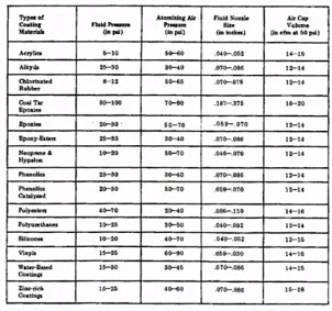
Table 2.1: Range of Pressures and Gun Nozzle Sizes for Spraying Common Coating Materials [8]
Data from Table 2.1 works as a guide for spray operator to choose appropriate replacement for fluid nozzle and air cap. Directly, this will also help to determine how to obtain optimize efficiency from the chosen spray gun by applying the suggested fluid and air pressure.
forces at work at the head of an air spray gun is the key to a successful spray application [3][9][10].
[image:21.595.228.402.187.333.2]The cross section of a conventional spray is as in Figure 2.2.
Figure 2.2: Cross-sectional Diagram of an External Mix Spray Gun [3]
Figure 2.3: Cross-sectional Diagram of an Internal Mix Spray Gun [3]
Figure 2.3 shows how the gun mixes air and material inside the air cap, before expelling them. It is usually used where low air pressures and volumes are available, or where slow-drying materials are being sprayed. A typical example is spraying flat wall paint, or outside house paint, with a small compressor. Internal mix guns are rarely used for finishing when a fast-drying material is being sprayed, or when a high quality finish is required [3]
2.1.2 High- Volume Low-Pressure Atomization (HVLP)
HVLP uses a high volume of air (typically between 15-26 CFM) delivered at low pressure (10 PSI or less at the air cap) to atomize paint into a soft, low-velocity pattern of particles. Usually, less than 10 psi is needed to atomize. Proper setup optimizes fluid and air pressure that is needed to produce the required quality. It will also results in a flow rate that will meet production requirements. Therefore, far less material is lost in overspray, bounce-back and blowback than with conventional air spray. This is why HVLP delivers a higher transfer than spray systems using a higher atomizing pressure. Transfer efficiency refers to the amount of solids applied as a percentage of solids sprayed.
models, particularly those using turbines to generate air, bleed air continuously to minimize backpressure against the airflow of the turbine [9]
The air cap design is similar to that of a standard spray gun, with a variety of air jets directing the atomizing air into the fluid stream, atomizing it as it leaves the tip. HVLP is growing in popularity and new environmental regulations are requiring it for many applications. HVLP can be used with any low-to-medium solids materials that can be atomized by the gun, including two-component paints, urethanes, acrylics, epoxies, enamels, lacquers, stains, primers, etc. [3] (Figure 2.4)
The HVLP atomization improved transfer efficiency, often approaching 65-75%, compliance with local finishing regulations, a softer spray that penetrates easily into recesses or cavities, reduced material (costs) consumption as well as reduced spray booth maintenance and reduced hazardous waste [7]. Turbine-operated HVLP systems enjoy great portability and ease of operation where compressed air is not available. HVLP spray guns with internal restrictors use existing air supplies, are easy to operate, and are low in cost.
Figure 2.4: Typical air atomization spray systems [7]
2.1.3 Airless Atomization
Airless spraying is a method of spray application that does not directly use compressed air to atomize the coating material. Hydraulic pressure is used to atomize the fluid by pumping it at high pressure (500-4,500 psi) through a small orifice (0.007-0.072 in.) spray nozzle tip located at the front of the airless gun [11] (Figure 2.5)
Airless atomization is speed of application. It is the fastest method of spray atomization. This process can deliver twice the amount of material as a compressed air system. Other advantages include improve transfer efficiency due to a reduction in fog and overspray, the ability to spray into recesses and cavities with a minimum of material bounce-back, and reduced spray booth maintenance.
HVLP produce coarse atomization. Automotive finishers and refinishers, for example, would not select airless atomization. Other limitations include less control of spray pattern when compared to air spray or HVLP.
Figure 2.5: Typical airless atomization spray systems [7]
2.1.4 Air- assisted Airless Atomization
Air-assisted airless was one that developed to fill a need that resulted from escalated material costs and newly enacted Environmental Protection Agency (EPA) regulations [2]
The primary advantage of air-assisted airless is its "soft" spray atomization. Atomization air pressures are usually low, and as a result, this system provides a fine finish with most coatings approaching that of compressed-air atomization. With air-assisted airless we can see an approximate 30% improvement in transfer efficiency over compressed air [7]. This system allows us to increase flow rates, while also spraying into recesses and cavities, without excessive bounce-back of material. This means less booth maintenance and clean-up time. We also can expect a reduction in compressed-air supply requirements. Since fluid pressures generally range from 200 to 800 psi, less wear on the pump and tip is to be expected.
Tip plugging may still be a problem with air-assisted airless. Many operators feel that air-assisted airless is too slow when compared to airless and that the finish is still not as good as compressed-air atomization. Many operators tend to use excessive fluid and air pressures with this process. There are more controls to learn to use it correctly.
2.1.5 Electrostatic Atomization
The need to use and the need to maximize the use paint, generated electrostatic atomization.. The coating is first atomized using either the compressed air, airless, or air-assisted airless methods previously discussed. Although these systems require equipment designed for electrostatic use, the atomization principles are the same as those for non-electrostatic applications. The atomized paint particles, at this point, are provided with forward velocity and direction.
is sufficiently grounded, particles that would have missed that part will now be drawn back or attracted to it [7].
The principal advantage of electrostatic spraying is the savings in material and labour. This process can provide transfer efficiency ratings from 65 to 95% if all conditions are favourable. Air velocity in the spray booth where electrostatic spraying is performed may be reduced from 100 to 60 ft./min. This means a 40% reduction in air makeup costs as well as reduced emissions [7].
Some users find excessive build-up on corners and edges. The parts that is intended to be sprayed electrostatically must always be conductive, either by virtue of the material from which it is made or through the application of a conductive pre-treatment [12].
2.2 Paint Composition and Characteristics
Paint can be defined as dispersion of pigments, optionally including fillers, in a fluid vehicle. The fluid vehicle comprises a liquid binder that will solidify during cure and, if necessary, a liquid carrier that serves as a viscosity reducing aid and will provide desirable application characteristic [13]. Paint is a liquid suspension of solid pigments in a combination of liquids called the vehicle. The vehicle consists of a drying oil, a drier and a volatile thinner. The manufacturing of paint involves mixing, grinding, thinning, tinting, straining, and canning operations [14].
Studies of the fluid dynamics of spray painting are limited. Most studies were done on the impact of paint spray to the safety, health and environment aspect; but not on the spray process and components included in process. However, significant contributions on these studies were made, for example, by Gerhard Zelder and Cord Steinbeck-behrens [16] on car body painting; Fogliati et al [17] for simulation of paint deposition in an air spray process and Hicks and Senser [18] on conventional air spray. Besides that, subject on airless spray painting and overspray effect were studied and researched upon by Settles [11].
2.2.1 Component
Typically, there are four main components in paint: binder, liquid, pigment, and additives. The solid pigment (or mixture of pigments) and a liquid medium (called the vehicle) are the prime components of any paint.
The vehicle consists of a drying oil (usually linseed oil), a drier (called, terebines) and a volatile thinner, (most often turpentine). When the paint is applied, the thinner evaporates rapidly. What’s left behind is a wet coating of pigment and oil. This mixture will gradually dries into an elastic solid skin by the evaporation of the oil or direct oxidation of the oil by air (cross-link). When the oil solidifies it acts as a binder to hold the particles of pigment together and in place; a tough paint film is thus formed which adheres firmly to the surface. It is this tough film that protects and decorates the surface. Paint When the Application methods depend on the particular paint, but can include spray application, brush methods, and electrostatic spraying.
2.2.1.1 Pigment and Filler
2.2.1.1.1 Pigment: Granular Solid Contribute To Colour (Prime Pigments) [12].
These pigments are mainly responsible for colour or whiteness in paint. It is also, the paint’s ability to hide undesirable surface flaws.
1. In paints that exhibit a white hue, titanium dioxide is the main ingredient.
2. In paints the express other colours, the pigments are selected to absorb only
certain kinds of light, thus yielding a given colour.
Organic pigments yield the brightest colons, while inorganic pigments yield less bright but more durable colours.
While pigments decorates and protects the surfaces for a while, it rubs off readily. To overcome this defect most paints contain a component called a binder [19].
2.2.1.1.2 Filler: Granular Solid Impart Texture or Toughness etc. [20]
These pigments are designed to add bulk, but are not as well suited to hiding surface flaws as prime pigments. It influences the paint’s overall sheen, colour retention, and abrasion resistance.
1. Silica and silicates, for example, are extender pigments that increase the paint’s
durability.
2. Zinc oxide helps prevent mildew and corrosion, and is especially useful in
outdoor applications.
2.2.1.2 Binder (Resin)
Binders include synthetic or natural resins and can be categorized according to the mechanisms for drying or curing. Although drying may refer to evaporation of the solvent or thinner, it usually refers to oxidative cross-linking of the binders and is indistinguishable from curing [12] Oxidative cross-links decreases flexibility increases hardness and melting point.
Depending on the ratio of pigment to binder, or the PVC (pigment volume concentration) the paint can assume varying levels of glossy finish. Paints with the glossiest finish often have typical PVC of 15 per cent, while the most matte paints have PVC anywhere from 40 to 80 per cent. Paints with less gloss have more binder per unit of pigment, and tend to be more durable. There are two specific types of binder: oil-based and latex-based [20]:
1. Oil-Based Binder:
Oil-based paint requires a binder that has similar properties to the paint—in this case, the binder oxidizes or dries when exposed to air, hardening along with the rest of the paint. Once applied, the liquid factor of an oil- based paint evaporates, and the binder then reacts with the air to harden into place with the pigment. However, sometimes this process can result in over-dry, brittle paint, and chipping can occur. Additionally, the oxidation makes the paint prone to yellowing [20].
2. Latex-Based Binder:
Recent environmental requirements restrict the use of volatile organic compounds (VOCs), and alternative means of curing have been developed, particularly for industrial purposes. In UV curing paints, the solvent is evaporated first, and hardening is then initiated by ultraviolet light. In powder coatings there is little or no solvent, and heating of the substrate produces flow and cure after electrostatic application of the dry powder [12].
2.2.1.3 Diluent or Solvent
The main purposes of the diluent are to dissolve the polymer and adjust the viscosity of the paint. It is volatile and does not become part of the paint film. It also controls flow and application properties, and in some cases can affect the stability of the paint while in liquid state. Its main function is as the carrier for the non-volatile components. To spread heavier oils (for example, linseed) as in oil-based interior house paint, thinner oil is required. These volatile substances impart their properties temporarily; once the solvent has evaporated, the remaining paint is fixed to the surface [12].
Solvents, which are ingredients of plastic coatings, have to be selected to reduce physical impact to the substrate, particularly in the case of acrylonitrile-butadiene-styrene (ABS) and polycarbonate (PC)–ABS blends. On the other hand, solvents also help to remove lipophilic contaminants and swell the substrates, and this contributes to better adhesion by increased molecular entanglement [21].
2.2.1.4 Additives
Co-solvents help the binder film formation and help prevent paint damage from occurring if the pain is frozen. Co-solvents also make application easier by lengthening the amount of time the paint can be open before beginning to set [21].
2.2.2 Application
Paint can be applied either as solid, gas or liquid. How the paint is actually applied, depends on the desired results, either practical or artistic. As for automotive paint, it is used on automobiles [12].
2.2.2.1 Solid
If the paint is applied as a solid, the paint is applied as a very fine powder. The following process would be baking it at high temperature. Baking melts the powder and causes it to adhere to the surface. This method is usually used in industrial and automotive applications
This application is called "powder coating" an object.
2.2.2.2 Gas
Paint applied as gas is actually in gaseous suspension form. The paint is suspended in solid or liquid form in a gas that is sprayed on an object [20]. This paint then sticks to the object.
This is called "spray painting" an object.
solvent to be sprayed along with the paint. By doing so it dissolves together both the delivered paint and the chemicals on the surface of the object being painted.;
2.2.2.3 Fluid
In the liquid application, paint can be applied by direct application using brushes, paint rollers, blades, other instruments, or body parts such as fingers and thumbs [12].
Rollers have handles that allow different lengths of poles to be attached. Elevating rollers on poles assist painting at different heights.
2.2.3 Techniques
There are 2 main concerns when it comes to techniques of applying the paint. First is painting for practical purposes and second painting for some aesthetic values.
2.2.3.1 Practical
Practically, paint is most commonly used to protect, colour (decorate), or provide texture to objects. Painting a car is one of the most expensive operations in automotive manufacturing. The painting operation typically comprises 30–50 % of an automotive assembly plant’s cost [6]. This high cost is as a result of two factors that is, the desire to have high quality coatings and the necessity of meeting strict environmental requirements. The coated surface must be finished in a manner that provides an outstanding coating surface quality.
meet the very complex requirements for gloss, colour durability, cracking resistance, adhesion throughout all layers, acid and chemical resistance, and scratch resistance [22].
2.2.3.2 Artistic
How then the artistic technique is being discussed? Sometimes, individuals want unusual, emotional custom looks for their vehicles, thus needing the spray operator to have an artistic edge to ‘connect’ and communicate with their customer. However, companies might have different priorities. Commercial vehicles often serve as carriers of advertising and information [23]. Entrepreneurs want their fleet to attract attention to their company, to differentiate themselves from their competitors. They therefore need an attention-grabbing look that stands out from the competition. At the same time, all relevant information must be visible and understandable at first sight. Needless to say, the spray operator has to be not only skilful but artistic as well.
2.3 Characteristic of Automotive Paint
Having discussed about resin in 2.2.1.2 on page 20; automotive paint resins are
usually one of the following three chemical compounds: lacquer, enamel, or urethane. Enamels are a softer resin, usually dry to a glossy finish, and are less expensive than urethanes. Urethanes are generally a more durable product but can be more difficult to spray. Most new cars are painted with a type of urethane, and most collision repair shops use urethane to repair damage. Lacquer is banned in pollution-controlled areas of certain the countries, but not Malaysia.
2.3.1 One- or Two –Part
One-part products are ready to spray. They may need to be diluted with a solvent. Sometimes the solvent is also referred to as a reducer or thinner. By diluting the paint, it may assist the mixture to flow through the spray gun properly. Unfortunately, they will dry on their own. It is by practice that the one-part paints are not used to repaint an entire car. Nearly all aerosol-can paints are one-part
Two-part products need an activator. The activator is referred to as a hardener. The hardener is use to stimulate the chemical reaction that causes the components of the paint to cross-link and bond to the surface of the car. This chemical reaction is referred to as "drying," though it really is not drying in the sense of evaporating.
Inactivated two-part paint will not dry if left on its own and therefore has a longer shelf life than one-part paint. Two-part products are also weatherproof and nonporous. Therefore painting the car in a 2K primer eliminates worry about the sheet metal rusting from the inside out [24].
2.3.2 Single-stage or Basecoat/Clear coat
Single-stage paint dries to a glossy finish and does not need a clear coat, whereas the basecoat, or colour coat, of a basecoat/clear coat (BC/CC) system dries to a matte or semi gloss finish.
REFERENCES
1. J. P. J. M. (JPJ), “Senarai Bengkel Kejuruteraan Negeri Perak,” 2014.
Retrieved on 29-Dec-2014, from http://www.jpj.gov.my/bengkel-perak.
2. EPA, “Control Technology: Automotive Refinishing Industry,” Washington
DC, 1994.
3. PAREXUSA Product Catalog,“Understanding Conventional & HVLP Spray
Guns,” PAREXUSA, California.
4. K. S. Manusia, Occupational Analysis Automotive Industry Department of
Skills Development. 2012, p. 391.
5. D. O. Chute, A. E. Health, and S. Services, “Risk Management Panel Project
Final Report,” no. 2012, pp. 1–46, 2013.
6. N. K. Akafuah, Automotive Painting Technology. Dordrecht: Springer
Netherlands, 2013, pp. 121–165.
7. J. P. Hund, “Application Methods: Spray Application Processes,” JPH
Finish. Consult., vol. 108, no. 11–12, pp. 133–149, 2011.
8. “Conventional Airspray.” Retrieved on 03-Nov-2014, from www.pati.org.
9. L. Landau, “HVLP Training Manual,” Zhurnal Eksperimental’noi i
Teoreticheskoi Fiziki. 1937.
10. T. S. Coatings, “TRIO Spray Finish Products for Finishing Excellence,”
2008.
11. G. Settles and J. Miller, “Visualization and collection of overspray from
airless spray painting,” Int. Symp. Flow Vis., 1998.
12. J. Li, D. E. Blumenfeld, and S. P. Marin, “Manufacturing System Design to
Improve Quality Buy Rate : An Automotive Paint Shop Application Study,”
vol. 4, no. 1, pp. 75–79, 2007.
13. J. V.Koleske, Mechanical Properties of Solid Coatings. Encyclopedia of
a. E. Bryson, “The Control Of Quality In The Manufacture Of Paint,”
Massachusetts Institute of Technology, 1950.
14. J. Jassbi, M. Alborzi, and F. Ghoreshi, “Car Paint Thickness Control Using
Articial Neural Network And Regression Method,” J. Ind. Eng. Int., vol. 7,
no. 14, pp. 1–6, 2011.
15. G. Zelder and C. Steinbeck-behrens, “Simulation on Car Body Painting
Processes,” no. July, pp. 2–7, 2009
16. M. Fogliati, D. Fontana, M. Garbero, and M. Vanni, “CFD simulation of
paint deposition in an air spray process,” JCT Res., vol. 3, no. 2, pp. 117–125,
2006.
17. P. G. Hicks and D. W. Senser, “Simulation of Paint Transfer in an Air Spray
Process,” J. Fluids Eng., vol. 117, no. 4, p. 713, 1995
18. NJIT, “2. Paints,” New Jersey Institute of Technology, 2012. Retrieved on
03-Nov-2014, from http://njcmr.njit.edu/distils/lab/paint_html/paint1.htm.
19. “General Industrial Paint Components,” 2014. Retrieved on 04-Nov-2014,
from, http://www.thomasnet.com/articles/chemicals/paint-components-general-industrial.
20. H.-J. Streitberger and K.-F. Dssel, Eds., Automotive Paints and Coatings,
Second, Co. Weinheim, Germany: Wiley-VCH Verlag GmbH & Co. KGaA, 2008, pp. 1 – 507.
a. Jurgetz, “Automotive paint performance,” Met. Finish., no. October, pp. 53–
55, 1995.
21. “Paint and Design.” Standox, Germany, pp. 1–32.
22. J. McGann, “Automotive Paint - Beginner’s Guide,” Hot Rod Network, 2007.
Retrieved on 01-Nov-2014 from, http://www.hotrod.com/how-to/paint-body/ccrp-0709-automotive-paint/.
23. D. Strohl, “Acrylic vs. Urethane,” Hemmings, 2007. Retrieved on
01-Nov-2014 from, http://www.hemmings.com.
24. A.E.P.Veldman (2012). Computational Fluid Dynamics. University of
Groningen. Faculty of Mathemathics and Natural Sciences
25. Przemek Sokołowski, retrived at 28/11/2014, from
26. 1.2.12. Additional Variables, retrived at 28/11/2014, from
http://www.arc.vt.edu/ansys_help/cfx_mod/i1298972.html .
27. Yunus A. Çengel, John M. Cimbala (2006). Fluid mechanics: fundamentals
and applications. McGraw-Hill Higher Education.
28. OMEGA Engineering inc 2003-2014, retrived at 28/11/2014, from
http://www.omega.com/techref/flowcontrol.html
29. N. ASHGRIZ, “Handbook of Atomization and Sprays: Theory and
Applications. Canada,” Springer. ISBN, 2011.
30. Juran, J. M.., Editor, & Gryna, F. M., Associate Editor. (1998). Juran’s
Quality Control Handbook, 4th edition, McGraw‐Hill Book Company, New
York.
31. Montgomery. D.C, and George C. Runger, (2003), Applied Statistics and
Probability for engineers, (John Wiley and sons).
32. ReliaSoft Corporation, retrieved at 29/11/2014, from
http://www.weibull.com/hotwire/issue85/relbasics85.htm
33. Introduction to Statistical Quality Control, 6th Edition by Douglas C.
Montgomery.Copyright (c) 2009 John Wiley & Sons, Inc.
34. Taguchi G, Konishi S ,Taguchi Methods, orthogonal arrays and linear graphs,
tools for quality American supplier institute, American Supplier Institute; 1987.
35. Ravella Sreenivas Rao, C. Ganesh Kumar, R. Shetty Prakasham, Phil J.
Hobbs (2008) The Taguchi methodology as a statistical tool for
biotechnological applications: A critical appraisal Biotechnology Journal 3:510–523.
36. Krishankant, Jatin Taneja, Mohit Bector, Rajesh Kumar (2012), Application
of Taguchi Method for Optimizing Turning Process by the effects of
Machining Parameters . International Journal of Engineering and Advanced Technology (IJEAT)
37. Mohamad Zaki M.S. (2013). A Numerical Study On Air-Fuel Mixture
Transportation To The Combustion Chamber Using Different Intake
38. W. A. Heitbrink, “A Control Matrix For Spray Painting at Autobody Repair
Shops,” Ohio, 1998.
39. Metin Ozen, OZEN ENGINEERING, INC, Meshing Workshop Ansys
training, retrieved at 23 May 2015 at 2.30 PM from www.ozeninc.com
40. Tingwen Li, Aytekin Gel, Sreekanth Pannala, Mehrdad Shahnam, Madhava
Syamlal 2014 . CFD simulations of circulating fluidized bed risers, part I: Grid study. National Energy Technology Laboratory, Morgantown, WV, US
41. M.D. Graham, F.T. Pinho, Journal of Non-Newtonian Fluid Mechanics,
retrieved at 29/11/2014 from http://www.journals.elsevier.com/journal-of-non-newtonian-fluid-mechanics
42. National Emissions Standard for Hazardous Air Pollutants (NESHAP),
retrieved at 29/11/2014 from
http://www.iowadnr.gov/portals/idnr/uploads/air/insidednr/neshap/6h_guide.p df
43. National Aeronautics of Space Administration, Reynolds Number, retrieved
![Figure 2.1: Parts of a Typical Air Spray Gun [9]](https://thumb-us.123doks.com/thumbv2/123dok_us/8765967.896441/19.595.226.410.218.364/figure-parts-typical-air-spray-gun.webp)
![Figure 2.2: Cross-sectional Diagram of an External Mix Spray Gun [3]](https://thumb-us.123doks.com/thumbv2/123dok_us/8765967.896441/21.595.228.402.187.333/figure-cross-sectional-diagram-external-mix-spray-gun.webp)
![Figure 2.3: Cross-sectional Diagram of an Internal Mix Spray Gun [3]](https://thumb-us.123doks.com/thumbv2/123dok_us/8765967.896441/22.595.221.418.72.218/figure-cross-sectional-diagram-internal-mix-spray-gun.webp)
![Figure 2.4: Typical air atomization spray systems [7]](https://thumb-us.123doks.com/thumbv2/123dok_us/8765967.896441/24.595.218.418.67.360/figure-typical-air-atomization-spray-systems.webp)
![Figure 2.5: Typical airless atomization spray systems [7]](https://thumb-us.123doks.com/thumbv2/123dok_us/8765967.896441/26.595.213.427.67.356/figure-typical-airless-atomization-spray-systems.webp)
