DEVELOPMENT OF MOBILE ROBOT IN VIRTUAL REALITY ENVIRONMENT FOR EDUCTIONAL PURPOSE
ABDULAZIZ SHAIF SALEH AL-GAHDARI
A thesis submitted in
fulfillment of the requirement for the award of the Degree of Master of Electrical Engineering
Faculty of Electrical and Electronic Engineering Universiti Tun Hussein Onn Malaysia
v
ABSTRACT
Pulse compression The intelligent system can help a robot to navigate through the environment by itself. The need for such system has become of essence especially when quality and accuracy is demanded in delivering complete processes of work in specific time. This project has focused on building a mobile robot that will be able to navigate and avoid collision. This thesis has aimed for developing a mobile robot in virtual reality environment for educational purposes. A robot has been developed using SolidWorks simultaneously with a suitable virtual environment. The integration of the mobile robot with the virtual reality environment has been obtained in 3D editor in Simulink Matlab. The robot has been made to move randomly in order to track different scenario possibilities. It has been found that the angular velocity from the calculation is approximately same as the one set for the simulation, which confirmed that there is no delay in the time. It has been found that the shortest and longest distance between the mobile robot and the obstacles are 11 mm and 108.7 mm for the sensor range of 85 mm and 150 mm respectively. The mobile robot has navigated through the office virtual environment and avoided collision with the obstacles.
ABSTRAK
vii
CONTENTS
CONTENTS PAGE
APPROVAL i
DECLARATION ii
DEDICATION iii
ACKNOWLEDGEMENT iv
ABSTRACT v
ABSTRAK vi
CONTENTS vii
LIST OF FIGURES x
LIST OF TABLES xii
LIST OF SYMBOLS AND ABBREVTIONS
LIST OF APPENDICES
xiii
xiv
CHAPTER 1: INTRODUCTION 1
1.1 Introduction 1
1.2 Problem statement 2
1.3 Objectives of Project 3
1.4 The Scope of The project 3
1.5 Research structure I. 4
CHAPTER 2 : BRIEF REVIEW ON SIMILAR PROJECT 5
2.1 Introduction 5
2.2 Path Planning 5
2.3 Path Tracking 6
2.3.1 Kinematic Constraints 7
2.3.2 Dynamic Constraints 8
Chapter 3 : METHODLOGY 16
3.1 Introduction 16
3.2 Project Flowchart 16
3.3 Design The Mobile Robot And The Environment Using SolidWork
17
3.3.1 Phase Design Of The Mobile Robot 18
3.3.1.2 Design the body 19
3.3.1.3 Caster Mount 19
3.3.1.4 Caster Wheel 20
3.3.1.5 Wheels 21
3.3.1.6 Assembly Phase 21
3.3.1.7 Summary of Dimension of mobile robot 23 3.3.2 Design the environment in solid works 23
3.4 Creating VRML Scene 25
3.4.1 Exporting mobile robot as VRML 25
3.4.2 Exporting Solid Works Environments as VRML 27 3.4.3 Assembling the Mobile Robot with the Environment
Models
28
3.5 Designing the Mobile Robot In Simulink 28
3.5.1 Exporting Solid Works Model using SimMechanics-Link
28
3.5.2 Importing SolidWorks Model (Xml) in SimMechanics Link
29
3.6 Designing the model in Simulink 31
3.6.1 Controller System (State Flow) 31
3.6.2 Virtual system sensor 33
3.6.3 Design the Lookup Data Table 34
3.6.4 Kinematics Model of the Robot 36
3.7 Simulink Model of the Mobile Robot 38
Chapter 4 : RESULT AND ANALYSIS 39
4.1 Introduction 39
4.2 Mobile Robot and the Environments 39
ix
4.2.2 Result of the Environments 41
4.3 Result of the Environment in VRML 3D Editor- Simulink 42
4.4 Result of the Map of the Environments 43
4.5 Simulation of the Mobile Robot Inside the Environment 44
4.5.1 Detecting the Obstacles 44
4.5.2 The Motion of the Mobile Robot 49
4.6 The Impact of Different Sensor Range in Path of the Mobile Robot
51
4.6.1 Sensor range (85 mm) 52
4.6.2 Sensor range (100 mm) 53
4.6.3 Sensor range (150 mm) 55
4.7 Summary 57
CHAPTER 5: CONCLUSIONS AND RECOMMENDATION FOR
THE FUTURE WORKS
58
5.1 Conclusions 58
5.2 Future Works 59
References 60
LIST OF FIGURES
Figures PAGE
2.1 Path Planning Configuration 6
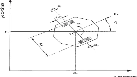
2.2 Definition of posture and velocities of two-wheeled mobile robot. 7
3.1 Project Flowchart 17
3.2 Flow chart of designing the Mobile Robot. 18
3.3 Front View For Body of The Proposed Design 19
3.4 Caster Mount 20
3.5 Caster Wheel 20
3.6 The Mobile Robot Wheels 21
37 Mate used in Assembly phase 22
3.8 Explore View of The Robot in Solid Works 22
3.9 Sketch View of the Environment (a) Room and (b) Office. 24
3.10 Saving Solid Works Model in (Wrl) Format. 26
3.11 Assembling the Mobile Robot in 3D Editor 26
3.12 Coordinates Of Caster Wheel 27
3.13 Assembling The Mobile Robot With Environment in 3D Editor 28
3.14 SimMechanics- Link Toolbox 29
3.15 Proposed Mobile Robot in Simulink 30
3.16 Controlling of the Mobile Robot 31
3.17 State Flow Algorithm 32
3.18 Top View Sensor Position 34
3.19 Corner of the Outer Wall of the Room Environment 35 3.20 Kinematic For Differential Wheel In Mobile Robot 36
3.21 Kinematic Subsystem in Simulink 37
3.22 Simulink Model For The Proposed Mobile Robot 38
xi 4.2 Mobile Robot. (a) Top view (b) Isometric View 40
4.3 Tope View of Room Environment 41
4.4 Tope View of Office Environment 41
4.5 Room Environment 42
4.6 Final Office Environment with the Mobile Robot 43
4.7 Map of the Room Environment 43
4.8 Map of the Office Environment 44
4.9 Ranges of the Sensors 45
4.10 Sensor Range and Dimension of the Robot. 45
4.11 Ranges of the Sensors in the Room Environment 46 4.12 (a) Left Most Sensor (1),
(b) Left Middle Sensor (2), (c) Front Sensor (3), (d) Right Middle Sensor(4) (e) Right Most Sensor(5)
47 47 48 48 48 4.13 Ranges of the Sensors in the Office Environment 49 4.14 Path of the Mobile Robot for Room Environment 49 4.15 Path of the Mobile Robot for Office Environment 50 4.16 4.17 4.18 4.19 4.20 4.21 4.22
Path of the Mobile Robot During 20 Second.
Path of the Mobile Robot for Office Environment with 85 mm All the Ranges of the Sensors in the Office Environment with 85 mm
Path of the Mobile Robot for Office Environment with 100 mm All the Ranges of the Sensors in the Office Environment with 100 mm
Path of the Mobile Robot for Office Environment with 150 mm All the Ranges of the Sensors in the Office Environment with 150
LIST OF TABLES
Tables PAGE
2.1 Related Works and Project Description that have Been Done 14
3.1 Mobile Robot Parameters 23
3.2 4.1
Velocity Representaion of Left And Right Wheel During Detection
Comparison table of different sensor range
xiii
LIST OF ABBREVIATIONS
DOF Degree Of Freedom
m Meter
Cm Centimetre
mm Millimetre
STL Stereo Lithographic Cad Systems
VRML Virtual Reality Modeling Language
WRL World Extension format
2D Two Dimensions
3D Three Dimension
XML Extensible Markup Language
CAD Computer-Aided Design
LIST OF APPENDICES
Appendices A Mobile Robot, Environments design, and path of the mobile robot in different scenario
64
CHAPTER 1
INTRODUCTION
1.1 Introduction
Since dawn of civilization, humanity has been slowly looking for different ways to make their life easier and lessen their pain of everyday life. Through this effort human being has improved the way they do things. They invented or developed new technologies that make things faster and more accurate. Man has always found himself a way to manipulate nature in order to serve him better. Man and machine may become powerful combination. As a result for that, machine can be delivering complete processes of work in specific time with high quality and accuracy.
Many autonomous mobile robots developed for structure environments rely on guide paths either embedded into their system or painted on the floor to navigate the robot around the desired workspace [1], [2]. Such mobile robots are adequate for point-to-point tasks where the guide paths do not change over time. Many researchers have realized that mobile robots may need to navigate around their environment without the use of guide paths.
Therefore the sensors have been invented and fabricated to allow the robots to sense the environment around and based on this input sensor signal, the robot can manipulate and perform based on the surrounding environment.
neural network Algorithm and fuzzy logic algorithm/controller (FLC), these systems make the robot act in fast response and stable as well. The major aim of this project is to build a mobile robot that will be able to navigate, avoid collision, by fulfilling these tasks the robot has achieved and completed the tasks that has been designed for [3].
1.2 Problem Statement
The intelligent system can help a robot to navigate through the environment by itself. It senses environment using sensor that feedback physical quantities. For instance, light, sound, distance and temperature of an object, but nonetheless it cannot comprehend the object itself like human being.
In order to build a map for indoor navigation, mobile robot must be endowed with avoid collision behaviour. This behaviour enables the robot to avoid the contour of a wall or an obstacle while applying an intelligent system.
3
1.3 Objectives of Project
The aim of this project is to develop of mobile robot in virtual reality environment for educational purpose. The objectives are formulated as follow:
I. To study a mobile robot in virtual environment.
II. To design a model of mobile robot in Solidworks and Simulink-MATLAB III. To implement stateflow controller as control system for the mobile robot to
void collision with the obstacles.
IV. To integrate the mobile robot design with in Virtual reality environment
1.4 The Scope of The project
The scopes of this project are:
I. Development the proposed structure of the robot and create a suitable virtual environment using SolidWorks environment.
II. Integration of the mobile robot with the virtual reality environment in 3D editor in Simulink- MATLAB
1.5 Research structure
I. Chapter 1 gives an overview of the project design. It covers the introduction to Mobile robot and, problem statement, objectives and the scope of work in this project.
II. Chapter 2 gives explanation on the robot, its applications, its advantages and disadvantages. This chapter also discuss the environments and how it been constructed. Finally, this chapter shows the previous studies that related to robot.
III. Chapter 3 discussed the procedure of designing the mobile robot and the environment, the procedure of creating the model in Simulink. This chapter also explains the way of implementation of virtual reality environment scene. IV. Chapter 4 presents the results obtained from the simulation process and
analyzing of the results in order to evaluate the performance of the proposed design that has been done.
5
CHAPTER 2
BRIEF REVIEW ON SIMILAR PROJECT
2.1 Introduction
Literature review is a process of collecting and analyzing data and information that are relevant to this study. The required data and information can be collected through variable sources such as journals, articles, reference books, online database and others. This chapter consists or two parts. The first part will be a case study on previous projects that relates to this project while the second part will focus on the theory aspects of this project.
2.2 Path Planning
Figure 2.1: Path Planning Configuration [33]
2.3 Path Tracking
7
2.3.1 Kinematic Constraints
In this section, the error dynamic and kinematical constraints of robot are defined. For a mobile robot driven by two differential wheels, the center of motion, denoted by C is located at the midpoint between the left and right driving wheels. Assuming that the robot moves on the planner surface without slipping, the tangential velocity and angular velocity at the center C can be written as [7].
𝑣𝑐 = 𝑟𝑤
2 (𝑤𝑟+ 𝑤1) (2.1)
𝑣𝑐 =
𝑟𝑤
𝑑𝑤 (𝑤𝑟+ 𝑤1) (2.2) where wr and wl denote the rotational velocities of the right and left driving wheels, respectively, is the radius of the wheels, and dw is the azimuth length between the wheels. The kinematic equation of the mobile robot is given by
𝑥̇𝑐 = 𝑣𝑐 cos 𝜃𝑐 (2.3)
𝑦̇𝑐 = 𝑣𝑐 sin 𝜃𝑐 (2.4)
[image:18.595.191.477.547.708.2]𝜃𝑐 = 𝑤𝑐 (2.5) where coordinates (xc ,yc ) indicate the position of the robot with respect to the world coordinate system and θc is the heading angle of the robot. The triplet (xc,yc,θc) is used for defining the robot posture and represented by vector P. The posture of the robot can be estimated from integration of Equations (2.3)–(2.5). The integration is implemented by the following iterative algorithm called dead reckoning.
(i) In case 𝑤𝑐 ≠ 0
𝑥𝑐𝑘+1= 𝑥𝑐𝑘+ 𝑣𝑐
𝑤𝑐 [sin(𝜃𝑐
𝑘+1) − sin(𝜃
𝑐𝑘)] (2.6)
𝑦𝑐𝑘+1= 𝑦𝑐𝑘+ 𝑣𝑐
𝑤𝑐 [sin(𝜃𝑐
𝑘+1) − sin(𝜃
𝑐𝑘)] (2.7)
𝜃𝑐𝑘+1= 𝜃𝑐𝑘+ 𝑤𝑐 𝑡𝑠 (2.8)
(ii) In case 𝑤𝑐 = 0
𝑥𝑐𝑘+1= 𝑥𝑐𝑘+ 𝑣𝑐 𝑡𝑠 cos(𝜃𝑐𝑘), (2.9)
𝑥𝑐𝑘+1= 𝑥𝑐𝑘+ 𝑣𝑐 𝑡𝑠 sin(𝜃𝑐𝑘), (2.10)
𝜃𝑐𝑘+1= 𝜃
𝑐𝑘 (2.11)
where k denotes the sampling index and is the sampling time
2.3.2 Dynamic Constraints
Any abrupt change in the robot motion may cause the slippage or mechanical damage to the mobile robot [7]. If the angular acceleration of each driving wheel is limited by ̇max.
|ẇ𝑟,1| ≤ ẇ𝑚𝑎𝑥 (2.12)
then, from (1) and (2), the tangential and angular accelerations of the robot are bounded by
|𝑎𝑐| + 𝑑𝑤
2 |𝑎𝑐| ≤ 𝑟𝑤ẇ𝑚𝑎𝑥 (2.13)
9
|𝑎𝑐| ≤ 𝑎𝑚𝑎𝑥 = 𝑟𝑤ẇ𝑚𝑎𝑥
2 (2.14)
|𝑎𝑐| ≤ 𝑎𝑚𝑎𝑥 =
𝑟𝑤ẇ𝑚𝑎𝑥
𝑑𝑤 (2.15) where and are the tangential and angular acceleration limits of the robot, respectively.
2.4 Related Work
There have been several studies done before to develop the path tracking algorithm for an autonomous mobile robot. The researched that had been studied is related to this project such as the method used to tracking the path.
K.C. Koh [7]has presented that dynamic constraints of the mobile robot should be considered in the design of path tracking algorithm. The driving velocity control law has been designed based on bang-bang control and the acceleration bounds of driving wheels need to be considered. The landing curve has been introduced as it works as an intermediate path smoothly steering the rotation of the robot towards the reference path. The target-tracking algorithm used in this project is composed of two independent laws, which are steering control law and velocity control law.
Sanhyuk [11] Park has studied the new guidance logic which is able to select a reference point on the desired trajectory and lateral acceleration command was generated by using the reference point. The several guidance logic have been developed which is the proportional derivatives controller (PD) has been used on the cross-track error, has an element of anticipation for the upcoming local desired flight path, and instantaneous vehicle speed was used in the algorithm. This kinematic factor adds an adaptive capability with respect to changes in vehicle inertial speed, due to the external disturbance.
pursuit algorithm is compared to other geometrical approaches, and it is shown to be more robust, resulting in more accurate path tracking.
J. Giesbrecht [13] has presented the pure pursuit algorithm implementation and adaptation. Pure Pursuit algorithm was chosen for its accuracy, simplicity, adaptability and robustness. The Pure Pursuit algorithm was implemented in four different ways which is as a path tracker to follow the straight line between high level waypoints on a patrol mission, goal directedness has been provided to obstacle avoidance behavior, a follower vehicle to pursue a lead vehicle via GPS breadcrumbs is allowed, and as a path tracker for a detailed on-line autonomous planner. This algorithm was devised to compute the arc necessary to return a vehicle back onto a path. It computes the curvature of an arc that a vehicle must follow to bring it from its current position to some goal position, where the goal is chosen as some point along the path to be tracked and the algorithm is extremely robust to poor sensing, poor actuation, combination with other control mechanisms, and is easily adapted for changing functionality. Another adjustable parameter has been implement is the radial tolerance that assigned to each waypoint. When the radial tolerance is set too low for the vehicle, the path is overshot at the corners. With a more realistic radial tolerance, the robot does not approach the waypoint itself as closely, but is able to adhere to the path more accurately.
R. Craig Conlter [14] has studied the implementation of the Pure Pursuit Path tracking Algorithm. The pure pursuit approached a method of geometrically determining the curvature that will drive the vehicle to a chosen path point, termed the goal point. The method itself is straightforward. The only real implementation problems lie in deciding how to deal with the path information (communication, graphics, updating the path with new information from the planner). There is one parameter in the pure pursuit algorithm, which is a look ahead distance. The effects of changing the look ahead distance must be considered within the problem faced such as regaining the path and maintaining the path.
two-11 layered FLC was used to make the UAV track its path while avoiding the fixed, but unexpected obstacles.
Jean-Matthieu bourgeot [16] has presented the path planner designed. It contains of two parts which is the references path need to be determined and tracking algorithm was applied which the robot followed the reference track. Using A has developed a 3D path planning method* algorithm to find the easiest track biped robot, then the low-level path tracking followed the path. For the path tracking strategy, heading and literal offset has been measured in the path tracking assignment.
G. Ambrosino [17] has studied the path generation and tracking algorithm for 3D UAV. The 3D path has been obtained by using Dubins Algorithm. Straight lines and circles/arcs of constant radii compose one of the characteristic of the path generated by the proposed algorithm. The line-of-sight guidance algorithm has been used for path tracking algorithm. This algorithm is based only on the kinematic equations of motion. The algorithm for the path tracking guarantees, under specified assumptions the tracking error, both in position and in attitude, asymptotically tends to zero.
Jacky Baltes [18] has presented the used of reinforcement learning in solving the path-tracking problem for car-like robots. The most important concept in reinforcement learning is the agent and environment. In the path-tracking problem, the reward is based on how well the agent tracked the given path. Reinforcement learning can be adapted to control a car in path tracking. The controller is needed to keeps the car on the track. The reinforcement controller is the only controller that has been used successfully to drive cars with and without linear steering behavior.
Takeshi Yamasaki [19] has studied about a guidance and control system for a trajectory-tracking unmanned aerial vehicle (UAV). A proportional navigation guidance law is applied to a tracking flight to achieve the robust trajectory-tracking guidance and control system. The system employed a dynamic inversion technique for the guidance force generation, which allows the UAV to maintain high maneuverability, and a simple velocity control to obtain a desired velocity. With the proportional navigation guidance, UAV may avoid its control saturation or divergence even in large tracking-error situations.
Guangfeng Yuan [9, 20] has developed tracking control approach for a car-like robot based on back stepping techniques and a neural dynamics model. The proposed control algorithm can generate smooth and reasonable velocity commands and deal with arbitrarily large tracking error. The advantage using back stepping is simple and stable. While the disadvantage is has a speed jump that has caused huge acceleration. The tracking control model can produced a smoothly changing velocity curve with time. The stability of the control systems are analyzed and proved using a Lyapunov stability theory.
A.Hemami [9] has proposed a new control strategy to determine the steering angle at each instant based on measured errors, the offset from the path and the deviation in orientation. The steering system is considered to control the angle of the steering wheel so that any deviation from the path is corrected in a stable manner and as fast as possible, and without oscillations about the path. Besides that, the dynamic equation of the vehicle is formulated to study the effect of a control strategy.
André KAGMA [21] has presented a method to track straight lines path with a car-like tricycle vehicle. Straight line tracking controller is used as a control strategy to track the path, as a robot is moves. The aim of this project is to design a controller which makes the vehicle follow the X – axis. Kinematics of the tricycle robot has been considered in this project.
The authors [27] have studied formation control of nonholonomic mobile robots considering obstacle avoidance. In addition, they have proposed potential functions of the distance between the real mobile robots and obstacles. There were two difficulties for the formation control in the presence of obstacles in the field. Firstly, the drawback of the virtual structure approach is that a real mobile robot may not be able to avoid an obstacle, even if the corresponding virtual robot can avoid it. Secondly, it may be difficult to maintain the desired formation depending on the location of obstacles. In this case, a new formation control method has been proposed which takes trade-off between the formation maintenance and the obstacle avoidance using a potential function of the distance between each mobile robot and obstacles. A numerical simulation has been conducted to verify the effectiveness of the proposed method over MATLAB/Simulink.
13
minimum rules that drive the mobile robot from a known starting position, regardless of the known or unknown scenarios with hurdles in cluttered environments. This method has three in puts hurdle distances obtained from left, right and front sensors and the output is single heading angle, which control the movement of mobile robot. This proposed method can be applied for mobile robot in different environments.
The authors [29] have present the use of virtual reality techniques in a robotics framework, Virtual Reality Engine provides realistic visualization of large offshore scene models in an immersive environment, by using this technique, the Immersive virtual environment reduces risks and costs of real operation tests scenarios.
The authors in [30] have proposed teleoperation systems for remote control of robot and the use of 3D virtual reality. The study has focused on the implementation and evaluation of the navigation of mobile robot integrated in telerobotics systems, which include the concept of 3D virtual reality. The authors have developed a mobile robot behavior in ASSET tool and validated simulation step using Fuzzy Logic Controllers (FLC).
The authors [31]proposed based on MATLAB / Stateflow two-wheeled robot
dance behavior analysis steps, this study has focused on FSM (Finite State Machine) theory as the foundation, based on the MATLAB / Stateflow graphical behaviour description method. Stateflow is a graphical language, simple and easy to understand, the modeling and programming process together, with visualization.
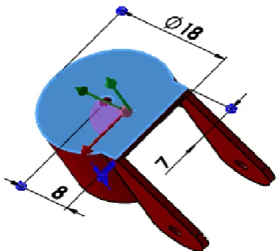
Table 2.1: list of Related Works and Project Description
Project Title Year Author Project Description A New Control
Strategy for Tracking in Mobile Robots and AGV’s
1990 A. Hemami, M.G. Mehrabi, and R.M.H. Cheng
Department of Mechanical Engineering Concordia University, Canada
Proposed a new control strategy that considers steering system. Formulated dynamic equation of the vehicle. A Simple Path
Tracking Controller For Car-Like Mobile Robots
1997 André Kamga and Ahmed Rachid
System automatic Laboratory France
Design and used straight line tracking controlleras a control strategy to track the path-Consider kinematic of the tricycle robot.
Path-tracking Control of-Non-holonomic Car-like Robot With Reinforcement
Learning
2000 Jacky Baltes and Yuming Lin Centre for image Technology and Robotics University of Auckland, Auckland New Zealand. Used reinforcement Learning and Reinforcement Controller. Autonomous Ground Vehicle Path Tracking
2000 Jeffrey S. Wit University of Florida
Used vector pursuit tracking technique.
Tracking Control of a Mobile Robot Using Neural
2001 Guanfeng Yuan The Faculty of Graduate Studies of The University
Used back stepping techniques and a neural dynamics model. - The stability of the control Path Planning And
Tracking in a 3D Complex Environment
for an
Anthropomorphic
2002 Jean – Matthieu Bourgeot, Nathalie Cislo, Bernand INRIA Rhone-Alpes, BIP Project, Montbonnot
3D path planning method develop by using
A*algorithm- Path tracking strategy measure heading and literal offset Path Tracking for
Unmanned Ground Vehicle Navigation
2005 J. Giesbrecht, D. Mackay, J. Collier, S. Verret DRDC Suffield Defence Research and Development
Used pure pursuit algorithm. Implement the radial tolerance waypoints.
Algorithms for 3D UAV Path Generation and
Tracking
2006 G. Ambrosino, M. Ariola, U. Ciniglio, F. Corraro, A. Pironti and M. Virgilio
Used Dubins Algorithm for 3D Path-Used line-of-sight guidance algorithm for tracking path.
Robust Trajectory-Tracking Method for
2007 Takeshi Yamasaki, Hirotoshi Sakaida, Keisuke Enomoto,
15 UAV Guidance Using
Proportional Navigation
Hiroyuki Takano and Yoriaki Baba Department of
Aerospace Engineering, National Defense
Employed a dynamic inversion technique for the guidance force generation.
Dancing behavior modeling and logic control simulation of two_wheeled robot based on Stateflow
2012 Yu, J., Yang, Q., Sun, L., &
Wang, G
Used MATLAB /
Stateflow based on finite state machine to as a controller for the wheeled robot
Remote control of mobile robot through 3D virtual reality environment
2013 Baklouti, E., Jallouli, M.,
Amouri, L., & Amor, N. B
Used concept of 3D virtual
reality for controlling mobile robot using using Fuzzy Logic Controllers Virtual reality
techniques for planning the offshore robotizing
2014 Carvalho, F., Raposo, A.,
Santos, I., & Galassi, M
Used virtual reality techniques in a robotics framework, Virtual Reality Engine
MATLAB Simulation for Mobile Robot Navigation with Hurdles in Cluttered Environment Using Minimum Rule based Fuzzy Logic Controller
2014 Pandey, A., & Parhi, D. R. Used a path-planning
system with Mamdani fuzzy logic navigation with knowledge.
Obstacle avoidance task for a wheeled mobile robot—a Matlab-Simulink-based didactic application.
2014 Silva-Ortigoza, R.,
Márquez-Sánchez, C., Carrizosa-Corral, F., Hernández-Guzmán, V. M., García-Sánchez, J. R., Taud, H., ... & Álvarez-Cedillo, J. A.
Used artificial potential
field method in carrying out the obstacle avoidance task with the wheeled mobile robot
Formation control of mobile robots with obstacle avoidance
2014 Miyazaki, T., & Takaba, K Used a potential functions
CHAPTER 3
METHODOLOGY
3.1 Introduction
This chapter discusses several steps need to be taken in conducting this project. Design procedures and software used are all discussed in this chapter. The flow chart represents guideline for procedures and steps for this project. It has explained the details about the SolidWorks, MATLAB and 3D editor software that have been used.
3.2 Project Flow chart
17
3.3 Design of the Mobile Robot and The Environment Using SolidWork
SolidWorks is Computer-Aided Design (CAD) software that offers tools to create, simulate manage and publish a 3D design. The powerful tools let the designer to visualize and simulate the design before the manufacturing process take place. SolidWorks is very popular due to its friendly usage and its several applications such as academic, research and development purposes also, in the industrial production for designing heavy-duty tools. One of the advantages of using SolidWorks is that it has powerful simMechanics-link tools that can convert the Solidworks model to Simulink blocks [22].
3.3.1 Phase of the Mobile Robot Design
This section is discussing about the steps and procedures of designing the mobile robot starting by designing each part separately and finally assembling it to create the integrated mobile robot. Figure 3.2 explains the steps for designing SolidWorks model.
Start
Parameters of the Design
Implement in SolidWorks
Mates the parts?
Convert SolidWorks file to XML (SimMechanics-link)
Successful?
Test the Mobile Robot in matlab
End
Yes
YES
Assembly the robot parts
Import XML file(SimMechanics-link)
Simulink MATLAB
NO
NO
19
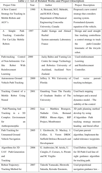
3.3.1.2 Design the Body
[image:30.595.241.407.246.423.2]The design of the robot takes the cylindrical shape in order to rotate inside the environment smoothly and without any collision with obstacles, unlike other shapes such as square shape which has four corners that might hit any corner during the motion. Figure 3.3 shows the structural of the body design.
Figure 3.3: Front View For of the Proposed Design
The wheel’s house has been trimmed out from the cylindrical shape (body’s base) in order to make the robot works as integrated unit, when the mobile robot moves and rotates the wheels will not hit the obstacles.
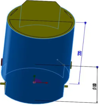
3.3.1.3 Caster Mount
Figure 3.4: Caster Mount
3.3.1.4 Caster Wheel
This part is separately designed and attached to the robot’s base by the caster mount in order to move freely and balanced during its motion. This free wheel rotation provides one degree of freedom (1DOF). Both caster mount and caster wheel provides (2DOF) which can minimize the number of blocks in Simulink after extracting from SolidWorks, and for making the simplicity of the system. The more the degree of freedom, the more extracting blocks in Simulink and the more complex the system to be controlled. Figure 3.5 shows caster wheel during design in SolidWorks.
[image:31.595.197.443.572.740.2]21
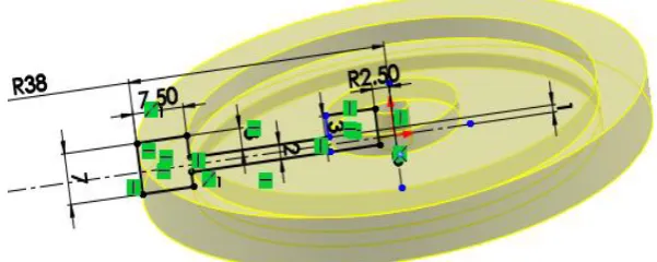
3.3.1.5 Wheels
[image:32.595.166.467.302.422.2]The left and right wheels are fit and mount on the left and right side of the robot respectively, the dimension of wheels are 38 mm radius, 7 mm thickness and 2.5 mm inner radius as illustrated in Figure 3.6. The distance between left and right of wheel’s house is shorter than the diameter of robot. When the robot moves and rotates, the wheels will not take extra space of the rotation. These wheels will be control by the controller which will be discuss in later topic.
Figure 3.6: The Mobile Robot Wheels
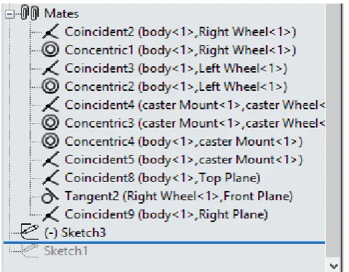
3.3.1.6 Assembly phase
Figure 3.7: Mate used in Assembly phase
[image:33.595.182.460.397.592.2]Figure 3.8 shows the mobile robot during the assembly phase where each part is located near its fixed position.
23
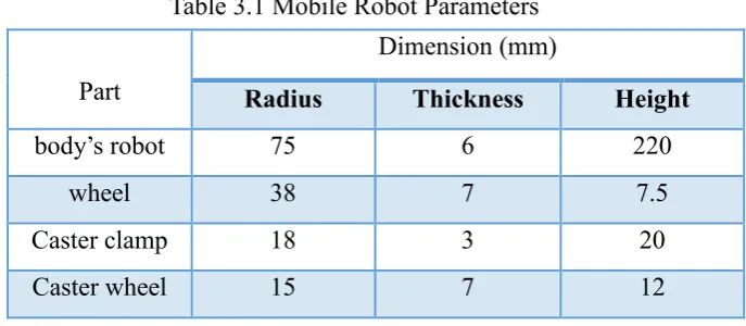
3.3.1.7 Summary of Dimension of Mobile Robot
Table 3.1 shows all the parameters discussed above, which were utilized during the designing phase. The dimensions of all the parts will be explained in details and attached in the appendix B
Part
Dimension (mm)
Radius Thickness Height
body’s robot 75 6 220
wheel 38 7 7.5
Caster clamp 18 3 20
Caster wheel 15 7 12
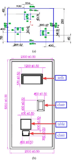
3.3.2 Designing the Environment in Solid Works
The environment in robotics is the workspace designed for the robot to work within in order to archive different task. In this work, it has been designed for two different environments, and each environment has different dimension of length and width as well as the position of the obstacles. First environment is about model of room with dimension of 2500 mm×2500 mm containing of three small chairs.
[image:34.595.146.490.223.373.2]However, the second environment is model of an office environment, which is more complex than the room environment in terms of the dimension, number of the obstacles and is more realistic to the real world. The office environment consists of an office table, chair, sofa and small chair. The dimension is 5000 mm×2500 mm, the wall thickness is 14 mm for the room environment and 100 mm for the office environment as shown in Figure 3.9 (a) and (b) show the dimension of the environments and the obstacles.
(a)
[image:35.595.198.454.65.628.2](b)
60
REFERENCES
1. Siegwart, R. and I.R. Nourbakhsh, Autonomous mobile robots. Massachusetts
Institute of Technology, 2004.
2. Mattaboni, P.J., Autonomous mobile robot, 1996, Google Patents.
3. Ng, K.C. and M.M. Trivedi, A neuro-fuzzy controller for mobile robot navigation
and multirobot convoying. Systems, Man, and Cybernetics, Part B: Cybernetics, IEEE Transactions on, 1998. 28(6): p. 829-840.
4. Kanayama, Y., et al. A stable tracking control method for an autonomous mobile
robot. in Robotics and Automation, 1990. Proceedings., 1990 IEEE International Conference on. 1990. IEEE.
5. Elnagar, A., & Basu, A. (1994). Piecewise smooth and safe trajectory
planning.Robotica, 12(04), 299-307..
6. Tounsi, M. and J. Le Corre, Trajectory generation for mobile robots.
Mathematics and computers in simulation, 1996. 41(3): p. 367-376.
7. Koh, K.C. and H.S. Cho, A smooth path tracking algorithm for wheeled mobile
robots with dynamic constraints. Journal of Intelligent and Robotic Systems, 1999. 24(4): p. 367-385.
8. Hemami, A., M. Mehrabi, and R. Cheng, Synthesis of an optimal control law for
path tracking in mobile robots. Automatica, 1992. 28(2): p. 383-387.
9. Hemami, A., M. Mehrabi, and R. Cheng. A new control strategy for tracking in
mobile robots and AGVs. in Robotics and Automation, 1990. Proceedings., 1990 IEEE International Conference on. 1990. IEEE.
10. Tsugawa, S. Steering control algorithm for autonomous vehicle. in Proc. of the
11. Park, S., J. Deyst, and J.P. How. A new nonlinear guidance logic for trajectory tracking. in Proceedings of the AIAA Guidance, Navigation and Control Conference. 2004.
12. Wit, J., C.D. Crane, and D. Armstrong, Autonomous ground vehicle path
tracking. Journal of Robotic Systems, 2004. 21(8): p. 439-449.
13. Giesbrecht, J., et al., Path tracking for unmanned ground vehicle navigation.
DRDC Suffield TM, 2005. 224.
14. Coulter, R.C., Implementation of the pure pursuit path tracking algorithm, 1992,
DTIC Document.
15. Dong, T., et al. Path tracking and obstacles avoidance of uavs-fuzzy logic
approach. in Fuzzy Systems, 2005. FUZZ'05. The 14th IEEE International Conference on. 2005. IEEE.
16. Bourgeot, J.-M., N. Cislo, and B. Espiau. Path-planning and tracking in a 3D
complex environment for an anthropomorphic biped robot. in Intelligent Robots and Systems, 2002. IEEE/RSJ International Conference on. 2002. IEEE.
17. Ambrosino, G., et al. Algorithms for 3D UAV path generation and tracking. in
Decision and Control, 2006 45th IEEE Conference on. 2006. IEEE.
18. Baltes, J. and Y. Lin, Path tracking control of non-holonomic car-like robot with
reinforcement learning, in RoboCup-99: Robot Soccer World Cup III. 2000, Springer. p. 162-173.
19. Yamasaki, T., et al. Robust trajectory-tracking method for UAV guidance using
proportional navigation. in Control, Automation and Systems, 2007. ICCAS'07. International Conference on. 2007. IEEE.
20. Yuan, G., Tracking control of a mobile robot using neural dynamics based
approaches. 2001: National Library of Canada= Bibliothèque nationale du Canada.
21. KAMAGA, A. and A. Rachid, A simple path tracking controller for car-like
mobile robots. choice, 1997. 1: p. 2.
22. Li, Y., et al. SolidWorks/SimMechanics-Based Lower Extremity Exoskeleton
62
23. Khaled, N., Virtual Reality and Animation for MATLAB® and Simulink® Users:
Visualization of Dynamic Models and Control Simulations. 2012: Springer Science & Business Media.
24. Dong, Z., et al. Real-time voxelization for complex polygonal models. in
Computer Graphics and Applications, 2004. PG 2004. Proceedings. 12th Pacific Conference on. 2004. IEEE.
25. Patil, S. and B. Ravi. Voxel-based representation, display and thickness analysis
of intricate shapes. in Computer Aided Design and Computer Graphics, 2005. Ninth International Conference on. 2005. IEEE.
26. Man, Z., Robotics. 2005: Pearson/Prentice Hall.
27. Miyazaki, T., & Takaba, K. (2014, October). Formation control of mobile robots
with obstacle avoidance. In Control, Automation and Systems (ICCAS), 2014 14th International Conference on (pp. 121-126). IEEE.
28. Pandey, A., & Parhi, D. R. (2014). MATLAB Simulation for Mobile Robot
Navigation with Hurdles in Cluttered Environment Using Minimum Rule based Fuzzy Logic Controller. Procedia Technology, 14, 28-34.
29. Carvalho, F., Raposo, A., Santos, I., & Galassi, M. (2014, July). Virtual reality
techniques for planning the offshore robotizing. In Industrial Informatics (INDIN), 2014 12th IEEE International Conference on (pp. 353-358). IEEE.
30. Baklouti, E., Jallouli, M., Amouri, L., & Amor, N. B. (2013, December). Remote
control of mobile robot through 3D virtual reality environment. In 2013 International Conference on Individual and Collective Behaviors in Robotics (ICBR).
31. Yu, J., Yang, Q., Sun, L., & Wang, G. (2012, July). Dancing behavior modeling
and logic control simulation of two_wheeled robot based on Stateflow. InIntelligent Control and Automation (WCICA), 2012 10th World Congress on (pp. 89-92). IEEE.
32. Silva-Ortigoza, R., Márquez-Sánchez, C., Carrizosa-Corral, F.,
Engineer, 79-102.
33. Ishigami, G., Nagatani, K., & Yoshida, K. (2007, April). Path planning for
planetary exploration rovers and its evaluation based on wheel slip dynamics.
In Robotics and Automation, 2007 IEEE International Conference on (pp.
![Figure 2.1: Path Planning Configuration [33]](https://thumb-us.123doks.com/thumbv2/123dok_us/8765446.896167/17.595.184.459.73.201/figure-path-planning-configuration.webp)