http://dx.doi.org/10.4236/ijmnta.2014.33011
PMSG Wind Energy Conversion System:
Modeling and Control
Omessaad Elbeji, Mouna Ben Hamed, Lassaad Sbita
Department of Electric Automatic, National Engineering School of Gabes, Gabes, Tunisia Email: [email protected]
Received 22 May 2014; revised 21 June 2014; accepted 4 July 2014
Copyright © 2014 by authors and Scientific Research Publishing Inc.
This work is licensed under the Creative Commons Attribution International License (CC BY).
http://creativecommons.org/licenses/by/4.0/
Abstract
In this paper, a model of a variable speed wind turbine using a permanent magnet synchronous generator (PMSG) is presented and the control schemes are proposed. The model presents the aerodynamic part of the wind turbine, the mechanic and the electric parts. Simulations have been conducted with Matlab/Simulink to validate the model and the proposed control schemes.
Keywords
Wind Turbine, Wind Energy Conversion System, Permanent Magnet Synchronous Generator, Speed Control, Current Control
1. Introduction
Renewable energy was strongly encouraged. It doesn’t produce emissions either provided by the sun, wind, wa- terfalls or plant growth. They participate in the fight against the greenhouse effect and CO2 emissions in the at- mosphere, facilitate rational management of local resources, and also create jobs. Solar (solar photovoltaic, solar thermal), hydro, wind, biomass, geothermal energy are inexhaustible resource of energy versus “energy stock” from fossil fuels deposits such us scarce oil, carbon, natural gas.
In this paper, study focuses on wind energy conversion systems. Indeed, wind energy has become a major pro- ducer of renewable electric energy.
A wind turbine generator system (WTGS) transforms the wind energy into electrical energy. In fact, wind turbines generate mechanical forces such as windmills of the past. Through their blades, wind turbine captures the wind kinetic energy and transforms it into mechanical one.
Then this later was transformed into electric energy by a generator.
magnet synchronous generator is selected for many reasons. A permanent magnet synchronous generator is cha- racterized by the absence of gearbox and reduced active weight, besides having a high power density and a high efficiency (disappearing of the copper losses in rotor).
Generally the wind turbine generator based on rotational speed can be splited into two types: fixed and varia- ble speed WTGS. Fixed speed turbines are easier to interface with the electrical grid. However, variable speed turbines are able to extract more energy from the wind and are the design preferred by the wind industry.
This paper interested to a variable speed WTGS. It has higher efficiency, especially at low wind speeds and also its power variations are lower than fixed speed turbines.
The paper analyzes a complete model of a variable wind turbine equipped with a permanent magnet synchron- ous generator it also proposes a vector control strategy to control the wind turbine generator. This strategy in- cludes a speed controller and two current controllers.
The wind conversion system model and the control schemes were verified using Matlab/Simulink. Simulations results are selected, dicussed and come to prove the obtained performances of the used controllers.
2. Wind Turbine Model
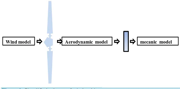
The wind energy captured by the blades was transformed by the wind turbine into mechanic energy.
The model studied is illustrated by Figure 1that contains the wind model, an aerodynamic part and a me- chanical model.
2.1. Wind Model
The wind speed model requires wind climate and geographical data of the concerned site and the period of the concerned year by the study. The wind model is given by a Fourier series representation of the wind which has as a signal consisting of a superposition of several harmonics. It is given by:
( )
( )
1
sin i
v k k
k
v t A a ω t
=
= +
∑
(1)where A is the average value of the wind speed, ak is harmonic amplitude of the order k, ωk is pulse har- monic of order k.
2.2. Aerodynamic Model
The aerodynamic energy of the wind can be represented as [1]:
3 1 2
w w
P = ρAv (2)
where A is the circular area, ρ is the air density, and vw is the wind speed.
[image:2.595.165.460.565.711.2]Using the wind aerodynamic energy, aerodynamic power can be produced by the turbine. It can be expressed by [2]:
Figure 1. Simplified scheme of wind turbine.
(
)
3 1
, 2
t w p
P = ρAv C β λ (3)
where Cp is the power coefficient, it depending on the pitch angle β and the tip speed ratio λ that given by [3]:
w
R v
λ=Ω (4)
where Ω is the turbine rotor speed, R is the turbine radius. Then the power coefficient Cp can be ex- pressed by [4]:
(
)
116 21, 0.5176 0.4 5 exp i 0.006795
p i
i
C β θ β λ λ
λ
−
= − − +
(5)
where λi is given by:
3 1 1 0.035
0.08 1
i λ
λ β β
=
−
+ +
(6)
p
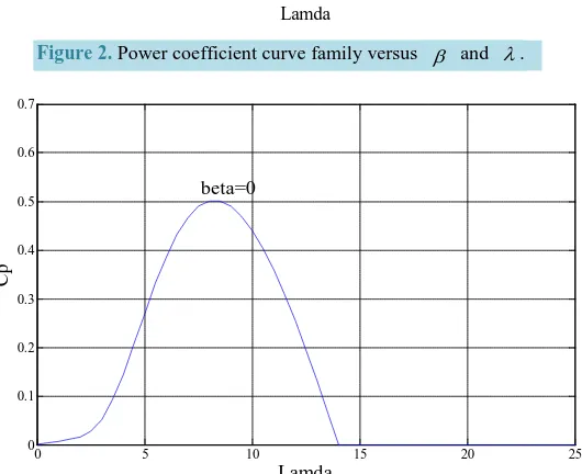
C is depending on λ and β, the Cp family of curve is obtained with different value of λ and with changing β value. This dependence is clearly visually inFigure 2.
[image:3.595.182.447.481.697.2]However, the power coefficient is maximal when β=0 that given by Figure 3.
Figure 2. Power coefficient curve family versus β and λ.
Figure 3. Power coefficient with different values of λ (with β=0).
0 5 10 15 20 25 30
0 0.1 0.2 0.3 0.4 0.5
Lamda
Cp
beta=20 beta=16
beta=12 beta=10
beta=8 beta=6 beta=4
beta=2
0 5 10 15 20 25
0 0.1 0.2 0.3 0.4 0.5 0.6 0.7
Lamda
Cp
To have best results, next simulations are carried with β =0. The aerodynamic torque is determined by [5]:
t t
P
T =
Ω (7) 3 2
0.5 π p t
R v C
T ρ
λ
= (8)
The aerodynamic turbine power curves family with varying the turbine rotor speed for different value of wind speed illustrated inFigure 4.
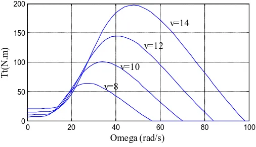
With varying the turbine rotor speed for different wind values, the curves family of the aerodynamic torque speed is given by Figure 5.
2.3. Mechanic Model
The fundamental dynamic equation is described with the following equation [2]:
d
d t em
J T T f
t
Ω= − − Ω
(9)
where Tem is the electromagnetic torque, f is the turbine rotor friction.
Then, the wind turbine generator drive that represents the mechanical bloc can be given by:
d d t em
T T J f
t
Ω
[image:4.595.187.442.351.530.2]− = + Ω (10)
Figure 4. Curve family of turbine power versus ω and v.
Figure 5. Curve family of aeodynamic torque versus ω and v.
0 20 40 60 80 100
0 2000 4000 6000 8000 10000 12000
Omega (rad/s)
Pt
(
W
)
v=8 v=10
v=12 v=14
0 20 40 60 80 100
0 50 100 150 200
Omega (rad/s)
Tt
(N
.m
)
v=10 v=12
v=14
[image:4.595.187.440.560.706.2]3. PMSG Model
The PMSG model can be written, in the d-q synchronously rotating reference frame, by the following equation system [1] [6]
d 1
d
d 1 1
d
q
d a
d q d
d d d
d a d
q d m q
q q q q
L
i R
i p i u
t L L L
i R L
i p i p u
t L L L L
ω ω ωφ = − + + = − − − + (11)
where d q, are the synchronous rotating reference frame; Ra is the armature resistance; Ld, Lq are the ge- nerator inductance on the d-q axis; id, iq are, respectively, the d- and q-axis components of current; uq, ud are the d- and q-axis voltage components, respectively, p is the pole pairs number and φm is the permanent magnet flux.
In the d-q synchronously rotating reference frame, the electromagnetic torque is represented by [1]:
(
)
(
)
3
. 2
em d q d q m q
T = n L −L i i +φ i (12)
4. Control Strategy
Vector control strategy is used to have more preferment results, to control the wind turbine.
As given in Equation (11) we have a problem of coupling between d- and q-axis, represented by the terms
q
p i
ω
and p iωd. Vector control concept is recommended, in order to overcome this problem of coupling4.1. Vector Control Strategy
Vector control strategy is based on the field orientation, id =0. Then according to (12), since φm is constant, the electromagnetic torque is directly proportional to iq [7].
Two inputs vd and vq are defined to compensate the cross-coupling terms [1] [8],
d q q d
v = Ωp L i +u (13)
e
q d d q q
v = − Ωp L i − +u (14)
where
eq = Ωφm (15)
d d
d
d d a d
i
v L R i
t
= + (16)
d
d q
q q a q
i
v L R i
t
= + (17)
4.2. Current Regulators
According to (16) and (17), two separate first-order models in the d-q axis [8] [9]. Thus,
(
1)
d
d d a
i
v = sL +R (18)
(
1)
q
q q a
i
v = sL +R
(19)
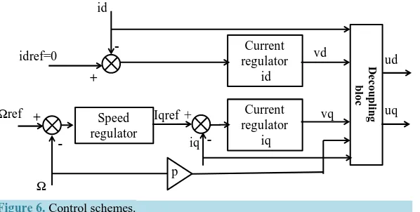
Figure 6. Control schemes.
4.3. Speed Regulator
Using the mechanical equation of wind turbine (10) the transfer function of the wind speed is written by:
(
Tt Tem)
Js f
− Ω =
+ (20)
Therefore, based on the last model the wind speed regulator is designed by a PI controller.Figure 6illustrates the overall schemes of the wind turbine control strategy. In fact, the speed controller takes as input the error be- tween the reference speed Ωref and the actual rotational speed. Where Ωref is obtained by λ expression as shown in (4), it can be represented by:
w ref
v R
λ
Ω = (21)
Then, the speed controller output presents iqref that is subtracted by the actual iq and the result is the input of the current regulator of the quadrature current component. The direct component has as input the results of the subtraction between the reference direct current idref that it is null in our strategy and the actual one id. The two controllers have as outputs the two voltage vd and vq that presents the inputs of the decoupling bloc. This later has as outputs the voltage components uq and ud which present also the outputs of overall control schemes [8] [10].
5. Simulations Results
Simulations are carried out, in order to prove the wind turbine model and the effectiveness of the proposed con- trol strategy. The block simulated is represented by Figure 7. It include, the different parts of the Wind Energy Conversion System [1] [11] such as the wind turbine model that has as input the electromagnetic torque Tem and the mechanic rotational speed Ω as output. The permanent magnet synchronous generator model which has three inputs; the two voltage components uq and ud and the electric rotational speed of the wind turbine
ω
. The control model take the quadrature current iq, the direct current id and the reference electric wind tur- bine rotational speedω
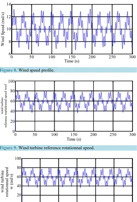
ref as inputs.The complete WECS bloc given byFigure 7 was built in Simulink and its simulation results are given by Figures 8-19. The wind turbine parameters and the PMSG one used in simulation are illustrated in the Appen- dix.
Simulations are carried with the following model:
( )
10 0.2sin 0.1047(
)
2sin 0.2665(
)
sin 1.293(
)
0.2sin 3.6645(
)
v t = + t + t + t + t (22)
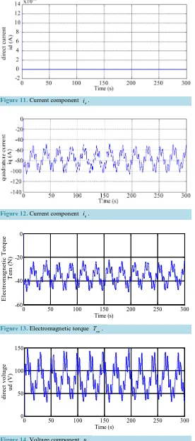
Simulation results demonstrate the performances of the wind turbine model and the vector control strategy. In fact, the output mechanical rotational speed Ω is assumed at the reference one Ωref; id is null as desired,
em
T is proportional to iq. Therefore the value of the power coefficient can be better than the current one as id
De
c
o
upl
ing
bl
o
c
-Current regulator
id
Current regulator
iq Speed
regulator
-+
+ Iqref +
idref=0
Ωref
Ω
iq
ud
uq vd
vq
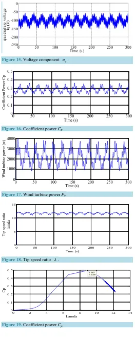
shown by Figure 19 Cp isn’t the maximum one so the wind turbine power also isn’t in the max and the tip speed ratio λ isn’t optimal as given byFigure 18. The real λ=12 but the optimum one is that illustrated by Figure 19when Cp is maximum λ=8.877.
Figure 7. Complete model of the wind energy conversion system.
[image:7.595.179.448.283.681.2]Figure 8. Wind speed profile.
Figure 9. Wind turbine reference rotationnal speed.
Figure 10. Wind turbine actual rotationnal speed. Wind turbine model Vector control strategy PMSG model p id Ωref iq uq ud Tem Ω ω
0 50 100 150 200 250 300
6 8 10 12 14 Time (s) Wi n d S p ee d ( ra d /s )
0 50 100 150 200 250 300
0 20 40 60 80 100 Time (s) w ind t ur bi ne ref er en ce r o p tat io n n al s p eed w ref
0 50 100 150 200 250 300
Figure 11. Current component id.
Figure 12. Current component iq.
[image:8.595.178.454.92.714.2]Figure 13. Electromagnetic torque Tem.
Figure 14. Voltage component ud.
0 50 100 150 200 250 300
-60 -40 -20 0
Time (s)
El
e
c
tr
o
m
a
g
ne
ti
c
Tor
q
u
e
T
em (N
)
0 50 100 150 200 250 300
0 50 100 150
Time (s)
d
ir
e
c
t v
ol
ta
g
e
u
d
(
Figure 15. Voltage component uq.
Figure 16. Coefficient power Cp.
Figure 17. Wind turbine power Pt.
[image:9.595.183.446.82.745.2]Figure 18. Tip speed ratio λ.
Figure 19. Coefficient power Cp.
0 50 100 150 200 250 300
0 0.1 0.2 0.3 0.4 0.5
Time (s)
C
o
ef
fi
ci
en
t P
owe
r C
p
0 50 100 150 200 250 300
0 1000 2000 3000 4000
Time (s)
Wi
n
d
t
u
rb
ine
p
o
we
r (
w)
0 50 100 150 200 250 300
0 5 10 15
Time (s)
Ti
p
s
p
ee
d r
at
io
la
m
da
0 2 4 6 8 10 12 14
0 0.1 0.2 0.3 0.4 0.5
X: 8.877 Y: 0.4937
Lamda
6. Conclusion
In this paper, the different bloc of the wind energy conversion system was studied and modeled. In fact, the model of the wind turbine has been presented, the permanent magnet synchronous generator using in variable speed wind turbine has been modeled, controlled and simulated. Using Matlab/Simulink, simulation results were carried when the proposed WECS model was confirmed and the performances of vector control strategy are substantiating.
We faced a number of problems, when making the different component model of the wind energy conversion system. First, the performances of the WECS are relied to the choice of pitch angle. Then, the aerodynamic power is related to the wind speed. And as assumed by simulation results, the coefficient power isn’t in its maximum, the speed ratio isn’t in the optimum one and the turbine power isn’t maximal. So, as results, trying to overcome these problems, we propose for the continuation of this chain of conversion energy controlling the pitch angle, studying and research of the maximum power point tracking to have more preferment results.
References
[1] Yin, M., Li, G., Zhou, M. and Zhao, C. (2007) Modeling of the Wind Turbine with a Permanent Magnet Synchronous Generator for Integration. IEEE, Power Engineering Society General Meeting, Tampa, 24-28 June 2007, 1-6.
[2] Carranza, O., Figueres, E., Garcera, G. and Gonzalez-Medina, R. (2013) Analysis of the Control Structure of Wind Energy Generation Systems Based on a Permanent Magnet Synchronous Generator. Applied Energy, 103, 522-538.
http://dx.doi.org/10.1016/j.apenergy.2012.10.015
[3] Qiu, Z., Zhou, K. and Li, Y. (2011) Modeling and Control of Diode Rectifier Fed PMSG Based Wind Turbine. DRPT: 4th International Conference on Electric Utility Deregulation and Restructuring, and Power Technologies, Weihai, 6-9 July 2011, 1384-1388.
[4] Thongam, J.S., Bouchard, P., Ezzaidi, H. and Ouhrouche, M. (2009) Wind Speed Sensorless Maximum Power Point Traking Control of Variable Speed Wind Energy Conversion System Electric Machines and Drives Conference, Miami, 3-6 May 2009, 1832-1837.
[5] Nath, S. and Rana, S. (2011) The Modeling and Simulation Wind Energy Based Power System Using MATLAB. In-ternational Journal of Power System Operation and Energy Management, 1, 12-17.
[6] Chen, X.F., Shu, Z.B. and Zhao, Y.K. (2005) Mathematic Model and Performance Analysis of PMSM, Based Servo System. Journal of Mechanism and Electronics, 1, 1-43.
[7] Sanchez, A.G., Molina, M.G. and Lede, A.M. (2012) Dynamic Model of Wind Energy Conversion Systems with PMSG- Based Variable-Speed Wind Turbines for Power System Studies. International Journal of Hydrogen Energy, 37, 10064-10069. http://dx.doi.org/10.1016/j.ijhydene.2011.12.077
[8] Bourourou, F., Louar, F. and Bourass, L. (2013) Simulation of Wind Conversion Chain Model with PI Voltage Regu- lation. Clearn Electric Power (ICCEP), Alghero, 11-13 June 2013, 707-711.
[9] Abdal Rassul Abbs, F. and Abdulla Abdulsada, M. (2010) Simulation of Wind-Turbine Speed Control by MATLAB.
International Journal of Comùputer and Electrical Engineering, 2, 912-915.
[10] El Magri, A., Giri, F., Besançon, G., El fadili, A., Dugard, L. and Chaoui, F.Z. (2013) Sensorless Adaptative Output Feedback Control of Wind Energy Systems with PMS Generators. Control Engineering Practise, 21, 530-543. [11] Muyeen, S.M., Al-Durra, A. and Tamura, J. (2011) Variable Speed Wind Turbine Generator System with Current
Controlled Voltage Source Inverter. Energy Conversion and Management, 52, 2688-2694.
http://dx.doi.org/10.1016/j.enconman.2011.02.001
Appendix
Wind turbine parameters PMSG parameters
ρ = 1.2 kg/ 3
m , R = 2 Ω
J = 0.002, f = 7E−4 2
m
d
L = 0.0066 H, Lq = 0.0058 H a
currently publishing more than 200 open access, online, peer-reviewed journals covering a wide range of academic disciplines. SCIRP serves the worldwide academic communities and contributes to the progress and application of science with its publication.