International Journal of Emerging Technology and Advanced Engineering
Website: www.ijetae.com (ISSN 2250-2459,ISO 9001:2008 Certified Journal, Volume 3, Issue 10, October 2013)
171
A Review of 3D Design Parameterization Using Reverse
Engineering
Shashank Alai
BE Student, Department of Mechanical Engineering, Sandip Institute of Technology & Research Centre, Nashik
Abstract—Reverse engineering plays an important role is
surface re-modeling. It is driving research in the 21st century
and encouraging multidisciplinary collaboration. The paper explores a reverse engineering approach for product form design. It presents a brief review of technical advancement in 3D shape engineering and design parameterization in reverse engineering, in which the discrete point clouds are converted into feature-based parametric solid models with the help of devices called 3D scanners and then exported to various 3D scanning software. The entire process consists in the acquisition, the point cloud alignment, the triangle model definition, the NURBS creation, the production of STL file, and finally the generation of a scaled replica of the prototype. It will also review the case study of design of a sports car model using 3D reverse engineering software and evaluation of these software. The paper will conclude with several state-of-the-art case studies from fields of computer arts, product development and medical with the extensive applications of the technique taken into consideration.
Keywords— 3D scanning, design parameterization, point cloud data, reverse engineering, shape engineering.
I. INTRODUCTION
Reverse engineering is the method that reconstructs CAD models from physical models. The main process of reverse engineering consists of data acquisition, data pre-processing, surface fitting, and making a CAD model. In reverse engineering, we mainly handle point data of the surfaces of a model acquired by measuring devices such as CMMs or 3D laser scanners. Usually a complex freeform shape model cannot be represented by a single patch, therefore, it must be divided into several less complicated surfaces.
The benefit of CAD/CAM is that the existence of computer models provides opportunities for improving the quality and efficiency of a design and is convenient for manufacture. Reverse engineering starts with measuring an existing object using a laser scanner, and then the measuring data is used to construct a surface or solid model.
Although reverse engineering technically does not include the machining process as one of its stages, an evaluation of the part dimensional accuracy after machining was nonetheless performed.
[image:1.612.372.508.265.399.2]Machining provides a physical model which can be compared easily to the original part, since better visualisation and measurement is possible.
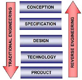
Figure 1: Traditional and Reverse Engineering.
Reverse engineering usually starts from a 3D object considered a prototype, it will be digitalized using whichever method and transposed in a CAD like software. The prototypes used in reverse engineering can be real or virtual. Figure 1 shows the principle of reverse engineering. From this figure we can see that in classical engineering we start from the technical idea and finish with the product, while in reverse engineering it’s backwards, we start from the product or an existing prototype and finish by digitalizing the object and assigning the specifications.
International Journal of Emerging Technology and Advanced Engineering
Website: www.ijetae.com (ISSN 2250-2459,ISO 9001:2008 Certified Journal, Volume 3, Issue 10, October 2013)
[image:2.612.95.244.130.275.2]172
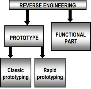
Figure 2: Reverse Engineering Solutions.
Although, converting data points into NURBS surface models has been automated, creating parametric solid models from data points cannot and will not be fully automated. This is because that, despite technical challenges in implementation, the original design intent embedded in the data points must be recovered and realized in the parametric solid model. Modeling decisions have to be made by the designer in order to recover the original design intents. However, designers must be relieved from dealing with tedious point data manipulations and primitive geometric entity constructions. Therefore, the ideal scenario is having software tools that take care of labor intensive tasks, such as managing point cloud, triangulation, etc., in an automated fashion; and offer excellent capabilities to allow designers to recover design intents interactively. Such an ideal scenario has been investigated for many years. After these many years, what can be done with the technology and tools developed up to this point? Many papers already address auto-surfacing. In this paper, we will focus on solid modeling and design parameterization.
II. DESIGN PARAMETERIZATION
One of the common approaches for searching for design alternatives is to vary the part size or shape of the mechanical system. In order to vary part size or shape for exploring better design alternatives, the parts and assembly must be adequately parameterized to capture design intents. At the parts level, design parameterization implies creating solid features and relating dimensions so that when a dimension value is changed the part can be rebuilt properly and the rebuilt part revealed design intents. At the assembly level, design parameterization involves defining assembly mates and relating dimensions across parts. When an assembly is fully parameterized, a change in dimension value can be automatically propagated to all parts affected.
Parts affected must be rebuilt successfully, and at the same time, they will have to maintain proper position and orientation with respect to one another without violating any assembly mates or revealing part penetration or excessive gaps. For example, in a single-piston engine shown in Figure 3[5] a change in the bore diameter of the engine case will alter not only the geometry of the case itself, but also all other parts affected, such as the piston, piston sleeve, and even the crankshaft. Moreover, they all have to be rebuilt properly and the entire assembly must stay intact through assembly mates, and faithfully reveal design intents.
Figure 3: A single-piston engine-exploded view, (a) bore diameter 1.2", and (b) bore diameter 1.6".
III. SHAPE ENGINEERING
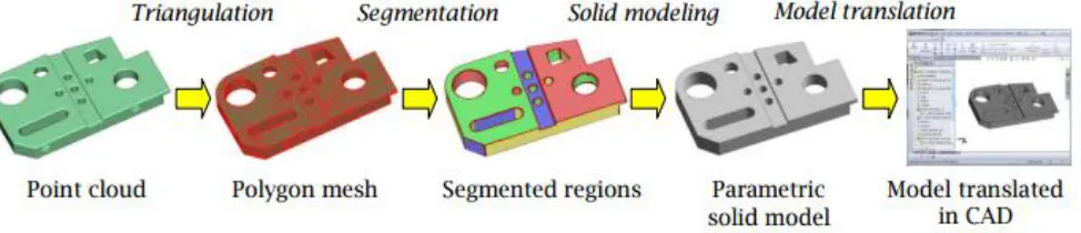
The overall process of shape engineering and parametric solid modeling is shown in Figure 4 in which four main phases are involved. They are (1) triangulation that converts data points to polygon mesh, (2) mesh segmentation that separates polygon mesh into regions based on the characteristics of the surface geometry they respectively represent, (3) solid modeling that converts segmented regions into parametric solid models, and (4) model translation that exports solid models constructed to mainstream CAD systems. Note that it is desired to have the entire process fully automated; except for Phase 3. This is because that, as stated earlier, Phase 3 requires designer’s interaction mainly to recover original design intents. These four phases are briefly discussed in the following subsections.
[image:2.612.341.555.270.376.2]International Journal of Emerging Technology and Advanced Engineering
Website: www.ijetae.com (ISSN 2250-2459,ISO 9001:2008 Certified Journal, Volume 3, Issue 10, October 2013)
[image:3.612.74.561.135.240.2]173
Figure 4: General process of shape engineering and parametric solid model construction.
A. Triangulation
The mathematical theory and computational algorithms for triangulation have been well developed in the past few decades. A polygon mesh can be automatically and efficiently created for a given set of data points. The fundamental concept in triangulation is Delaunay triangulation. In addition to Delaunay triangulation, there are several well-known mathematic algorithms for triangulation, including marching cubes, alpha shapes, ball pivoting algorithm (BPA), Poisson surface reconstruction, moving least squares [2], etc.
B. Segmentation
One of the most important steps in shape engineering is mesh segmentation. Segmentation groups the original data points or mesh into subsets each of which logically belongs to a single primitive surface.
In general, segmentation is a complex process. Often iterative region growing techniques are applied [6-8]. Some use non-iterative methods, called direct segmentation [9], that are more efficient. In general, the segmentation process, involves a fast algorithm for k-nearest neighbors search and an estimate of first- and second-order surface properties. The first-order segmentation, which is based on normal vectors, provides an initial subdivision of the surface and detects sharp edges as well as flat or highly curved areas. The second-order segmentation subdivides the surface according to principal curvatures and provides a sufficient foundation for the classification of simple algebraic surfaces. The result of the mesh segmentation is subject to several important parameters, such as the k value (number of neighboring points chosen for estimating surface properties), and prescribed differences in the normal vectors and curvatures (also called sensitivity thresholds) that group the data points or mesh.
C. Solid Modeling
Solid modeling is probably the least developed in the overall shape engineering process. Boundary representation (B-rep) and feature-based are the two basic representations for solid models.
There has been some methods, such as [9], proposed to automatically construct B-rep models from point clouds or triangular mesh. Some focused on manufacturing feature recognition for process planning purpose, such as [10]. One promising development in recent years was the geometric feature recognition (GFR), which automatically recognizes solid features embedded in B-rep models.
However, none of the method is able to fully automate the construction process and generate fully parametric solid models. Some level of manual work is expected.
1. Boundary Representation: Based on segmented regions (with fitted surfaces), a region adjacent graph is built, which reflects the complete topology and serves as the basis for building the final B-rep model, also called stitched models, where the individual bounded surfaces are glued together along their common edges. In general, there are three steps involved in constructing B-rep models, flattening, edges and vertices calculations, and stitching [9]. In flattening step, regions are extended outwards until all triangles have been classified. Note that this step is necessary to remove all gaps between regions. Sharp edges can be calculated using surface-surface intersection routines, and vertices where three surfaces meet are also determined. During the process, a complete B-rep topology tree is also constructed. A B-rep model can then be created by stitching together the faces, edges, and vertices. This operation is commonly supported by most solid modeling kernels.
International Journal of Emerging Technology and Advanced Engineering
Website: www.ijetae.com (ISSN 2250-2459,ISO 9001:2008 Certified Journal, Volume 3, Issue 10, October 2013)
174 D. Model Translation
Since most of the promising shape engineering capabilities are not offered in CAD packages (more details in the next section), the solid models constructed in these reverse engineering software will have to be exported to mainstream CAD packages in order to support common engineering assignments.
The conventional solid model translation via standards, such IGES or STEP AP (application protocols), are inadequate since parametric information, including solid features, feature tree, sketch constraints and dimensions, are completely missing in the translation. Although feature recognition capability offers some relief in recognizing geometric features embedded in B-rep models, it is still an additional step that is often labor intensive. Direct solid model translations have been offered in some software, such as liveTransfer™ module of Rapidform XOR3 and third party software, such as TransMagic [15].
IV. CASE STUDY
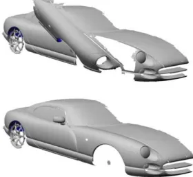
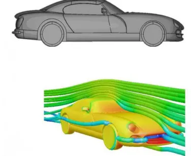
[image:4.612.341.545.267.405.2]The reverse engineering process is applied to a complex hand-made sports car (TVR Cerbera) as seen in Figure 5.
Figure 5: TVR Cerbera-Sports Car used for the study.
This part is chosen because of its complex shape encompassing varied details such as grooves, lights and air holes. For the purpose of this 3D object it is necessary for the final surfaces to reach a high quality standard. Only one half of the car is studied here, the other half being created by symmetry.
A. Material and digitization from components
A seven-axis articulated measuring arm (Cimcore 2.8 m) equipped with a laser scanner (Perceptron V4) which generate a line of points at the rate of 23,000 points per second was used to scan the external surface and create a precise image as shown in Figure 6.
[image:4.612.63.274.397.538.2]This car is a fairly large object and thus, to produce a suitable polygonal model, the arm was positioned in a dozen of different arrangements in order to collect all the data desired and scan the component in various directions. A total of about 3000 scans were taken. It took three days to scan half of the car. The time required to scan the car could have been reduced by using other scanner technologies. The reverse engineering software used for pre-processing the data is PolyWorks V9. It is a proprietary software package that deals with cloud points, mesh repair, surface generation and inspection.
Figure 6: Perceptron V4 laser scanner is used for the study.
However, the successive stages described here could be carried out in a similar fashion using any other reverse engineering package.
As the body is scanned, images must meet two criteria. Firstly, each group of scans has to share adjacent data with other groups. Secondly, each image overlap should contain shape variations as the algorithms do a shape-based alignment to bring all scans in the same coordinate system.
B. Preprocessing of the point clouds
The scans are imported into a module where they are treated to remove irrelevant points. When all of the scans are ready the alignment can commence [11].
[image:4.612.375.515.583.712.2]International Journal of Emerging Technology and Advanced Engineering
Website: www.ijetae.com (ISSN 2250-2459,ISO 9001:2008 Certified Journal, Volume 3, Issue 10, October 2013)
175
The first portion of the car is locked with its corresponding scans fixed and all the subsequent scans for other parts will be aligned relatively to them (see Figure 6). This rough and automatic alignment is carried out semi-automatically by picking common points from the adjacent pieces. This initial alignment will be improved by an iterative best-fit alignment for an optimal and accurate alignment. These scans can now be positioned and the process is repeated until the point cloud is shaped. When all the scans seem aligned, the last action consists of optimizing the pre-alignment. Again, a best-fit alignment is used to generate the final cloud points. The point clouds data are now ready for meshing.
C. Generation of the initial mesh
Once the point cloud is edited, the triangulated mesh can be produced. A high-resolution and accurate polygonal model is generated from sets of aligned scans. However, at this stage the merged model is not complete and further improvement is required to deal with some imperfections. About three hours were necessary to merge data and produce an initial mesh.
D. Optimization of the mesh
The triangulated model obtained from the meshing stage has various imperfections such as holes and gaps and needs to be refurbished and optimized [12].
[image:5.612.366.523.275.377.2]Abnormal triangles such as residuals over the whole model are first deleted. Small holes are quickly filled in automatically but a manual operation has to be performed to surface over large holes and gaps in a proper and accurate way. Bezier surfaces are used to repair these areas by fitting them to triangles surrounding the holes. The geometry is then repaired and re-meshed locally.
Figure 8: Optimized mesh as an STL file.
E.Surface Creation
Boundary and feature curves are first extracted either automatically or manually for meticulous shape. Feature shape is a representation of shape aspects that are map-able to a generic shape. For example, chamfer and rounding are geometric features and therefore curves can be extracted by tracking lines of curvature.
Many other curves are then created manually to generate further various quadrilateral patches. A curve network is thus built from a set of magnetized curves. Two magnetized curves have a common control point at their intersection in the Hermite representation. The basic curve element for constructing complex composite curves is the parametric cubic curve.
[image:5.612.348.536.517.670.2]Patches tends to have four boundaries in order to respect continuity with other adjacent patches but in some cases a three-sided patch can be created. To get rid of any wrinkles and waves on surfaces, T-junctions are located in flat areas.
Figure 9: Final CAD Model.
In the case where a patch has more than 5 boundaries, this will result in a hole on the surface of the final model. Finally, generation of NURBS surfaces is performed automatically within minutes. To obtain a suitable CAD model which fallows accurately the mesh, the number of control points per boundary is set to 6. A greater number of control points are not necessary because of the heaviness of the model that could be obtained.
[image:5.612.56.281.532.613.2]International Journal of Emerging Technology and Advanced Engineering
Website: www.ijetae.com (ISSN 2250-2459,ISO 9001:2008 Certified Journal, Volume 3, Issue 10, October 2013)
176 F.Result
1. Accuracy:Accuracy is quantified by the deviation of the surface from its original mesh. As expected, surfaces from rapid surfacing techniques follow more accurately the mesh: approximately 95% of NURBS are within +/- 0.3 mm whereas in the manual method 95% of NURBS are within 1.5 mm.
In the manual method, prolonged time period were required to achieve this range of errors but with more time and effort errors could have been slightly reduced.
2. Quality: In this case where the final CAD model must achieve a perfect visual finish, rapid surfacing techniques are likely to reach a sufficient high standard since classical surfacing produces far higher quality surfaces.
3. Time:Rapid surfacing techniques allow the operator to quickly create a CAD model within hours when approximately 6 to 7 days were required to model the car using classical surfacing.
V. ENGINEERING SOFTWARE
The most useful and advanced shape engineering capabilities are offered in specialized, non-CAD software, such as Geomagic, Rapidform, etc., that are intended to support reverse engineering. Some CAD packages, such as SolidWorks, Pro/ENGINEER Wildfire, and CATIA, offer limited capabilities for shape engineering. In general, capabilities offered in CAD are labor intensive and inferior to specialized codes while dealing with shape engineering.
[image:6.612.340.548.603.678.2]After intensive review and survey [13], to the authors’ knowledge, the best software on the market for reverse engineering is Geomagic Studio v11 and Rapidform XOR3. This was determined after a thorough and intensive study, following a set of prescribed criteria including auto-surfacing, parametric solid modeling, and software usability. Between the two, Geomagic has a slight edge in geometric entity editing, which is critical for auto-surfacing (construction NURBS surface models). In terms of solid modeling, Geomagic stops short at only offering primitive surfaces, such as plane, cylinder, sphere, etc., from segmented regions.
Figure 11: Lofted model of sheet metal part (16in.×10in.×9in.), (a) polygon mesh of 134,089 polygons, (b)lofted model using two section
profiles and four guide curves, and (c) geometric error analysis.
Rapidform is superior in support of solid modeling (in addition to excellent auto-surfacing) that goes beyond primitive surface fitting. Rapidform offers convenient sketching capabilities that support feature-based modeling. As a result, it often requires less effort yet yielding a much better solid model by interactively recovering solid features embedded in the segmented regions.
The interactive approach mainly involves creating or extracting section profiles or guide curves from polygon mesh, and following CAD-like steps to create solid features; for example, sweep a section profile along guide curves for a sweep solid feature. For example, an airplane sheet metal part was constructed by lofting two end section profiles with four guide curves, as shown in Figure 11. The loft model is very accurate. As shown in Figure 11(c), the geometric error in average and standard deviation between the lofted model and the polygon mesh are -0.021 and 0.049 in., respectively (using Accuracy Analyzer of Rapidform).
Focus of the paper is given to feature-based solid modeling. Only selected examples for Geomagic and Rapidform are presented to illustrate the detailed steps and essential capabilities in the software.
A. Geomagic Studio V11
Geomagic automatically recognizes primitive surfaces from segmented regions. If a primitive surface is misrecognized or unrecognizable, users are able to interactively choose the segmented region and assign a correct primitive type. Often, this interactive approach leads to a solid model with all bounding surfaces recognized. Unfortunately, there is no feature tree, and no CAD-like capabilities in Geomagic. Users will not be able to see any sketch or dimensions in Geomagic Studio v.11. Therefore, users will not be able to edit or add any dimensions or constraints to parameterize the sketch profiles. Section sketches only become available to the users after exporting the solid model to a selected CAD package supported by Geomagic.
[image:6.612.53.285.619.689.2]International Journal of Emerging Technology and Advanced Engineering
Website: www.ijetae.com (ISSN 2250-2459,ISO 9001:2008 Certified Journal, Volume 3, Issue 10, October 2013)
177
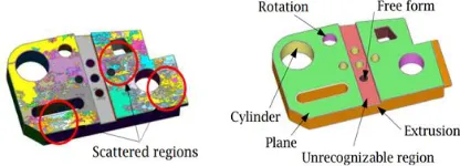
The block example (3in.×5in.×0.5in.) of 634,957 points shown in Figure 12(a) is employed to illustrate the capabilities offered in Geomagic. As shown in Figure 12(b) primitive surfaces in most regions are recognized correctly. However, there are some regions incorrectly recognized; for example, the hole in the middle of the block was recognized as a free-form primitive, instead of a cylinder.
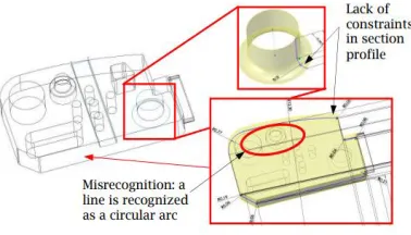
[image:7.612.358.532.138.285.2]There are also regions remained unrecognized; e.g., the middle slot surface. Although most primitives are recognized in Geomagic, there are still issues to address. One of them is misrepresented profile. One example is that a straight line in a sketch profile may be recognized as a circular arc with a large radius, as shown in Figure 13 (this was found only after exporting the solid model to SolidWorks). The sketch profile will have to be carefully inspected to make necessary corrections, as well as adding dimensions and constraints to parameterize the profile.
Figure 13: Extracted primitive surfaces in SolidWorks.
Unfortunately, such inspections cannot be carried out unless the solid model is exported to supported CAD systems. Lack of CAD-like capability severely restricts the usability of the solid models in Geomagic, let alone the insufficient ability for primitive surface recognition.
B. Rapidform XOR3
[image:7.612.73.262.341.449.2]Rapidform offers much better capabilities than Geomagic for parametric solid modeling. Excellent CAD-like capabilities, including feature tree, are available to the users. These capabilities allow users to create solid models and make design changes directly in Rapidform. For example, users will be able to create a sketch profile by intersecting a plane with polygon mesh, and extrude the sketch profile to match the bounding polygon mesh for a solid feature.
Figure 14: A parametric solid model of the block example created using Rapidform, (a) fully parameterized section sketch, (b) extrusion
for the base block, and (c) design change.
On the other hand, with the feature tree users can always roll back to previous entities and edit dimensions or redefine section profiles. These excellent capabilities make Rapidform particularly suitable for parametric solid modeling. Rapidform offers two methods for solid modeling, Sketch, and Wizard, which offers fast and easy primitive recognition from segmented mesh. The major drawback of the Wizard is that some guide curves and profile sketch generated are non-planar spline curves that cannot be parameterized. Users can use either or both methods to generate solid features in a single part.
The solid models created in specialized software, such as Rapidform and Geomagic, have to be translated to mainstream CAD systems in order to support engineering applications. Both Rapidform and Geomagic offer capabilities that export solid models to numerous CAD systems.
VI. INTERESTING APPLICATION
A. Computer Arts
International Journal of Emerging Technology and Advanced Engineering
Website: www.ijetae.com (ISSN 2250-2459,ISO 9001:2008 Certified Journal, Volume 3, Issue 10, October 2013)
178
Reverse engineering is used to create realistic digital representations of props or figures that will be transformed and realized on screen. Occasionally the major artistic inspiration for the feature characters in a game or movie comes from a sculpted model or hand crafted figurine. The ―one of a kind‖ piece is scanned and the point cloud translated into a workable data set. Individual humans, as opposed to manikins can also be scanned to ensure proportion and facial resemblance.
B. Design/Product Development
The reverse engineering process is a key step for manufacturing companies to create innovative products. After an industrial designer sculpts a clay model or creates a wooden mock-up, a 3D laser scanner is used to digitize the model into 3D point cloud data. In order to edit the file, it must be transformed into a polymesh file or NURBS based model with software tools. A functional prototype can be quickly produced in just a few hours, after generating accurate tool paths with CAM software. Digitization as a reverse engineering tool grew, in part, out of the requirements of manufacturers that rely heavily on physical models [14].
C. Medical
Medical scan technology has an important place in the area of bone and tissue reconstruction. Implants and prostheses can be tailored to meet a patient’s exact requirements, helping a wide range of people, including victims of bone disease, cancer, congenital defects and traumatic injuries. The data from non-intrusive scans, such as CT or MRI, is used to create a 3D model allowing technicians to perfect the shape, performance and integration of the implant into existing structures within the body. Several research organizations use RapidForm's 3D imaging technology to convert CT & MRI scans into CAD models for advanced neurosurgical and biomechanical research, and to build rapid prototype copies of the anatomy. Stereo-lithography takes these images and converts them to polymerized resin 3-D models allowing doctors to hold the information in their hands and examine all of the data at once. A more complicated approach is to fit a mathematical surface of lofted polynomial curves to the cross sectional boundary data from the successive serial scans. The Bernstein basis function network is an example approach to performing the functional approximation task necessary for reverse engineering bone structures, with the end goal of producing a customized implant.
VII. CONCLUSIONS AND FUTURE DIRECTIONS
In this paper, technology that enables 3D shape engineering and design parameterization for reverse engineering was briefly reviewed.Software that offers such capabilities was also evaluated and tested using practical examples.mention in the text.
In this paper, we have presented a case study of 3D design parameterization and reverse engineering of large free form surfaces applied to the automotive domain. The various steps leading to the CAD models and to the scaled replica of a prestigious car have been described and commented. The results obtained highlighted the capabilities of our range system to on-site accurate measurements of 1:1 car bodies, even in the presence of non-cooperative surfaces. Reverse engineering capabilities allow designers to use input from physical components at every stage of the design-to-manufacturing process. This approach not only allows for accurate design representation and rapid comparisons of physical legacy data, but also bridges the physical-to-digital environments. Geometric representation can be created in a fraction of the time of conventional CAD systems.
The ideal scenario can now be realized by using software such as Rapidform for shape engineering and parameterization, where labor intensive tasks, such as managing point cloud, triangulation, etc., is taken care of in an automated fashion; and design intents can be recovered interactively as desired.
It is anticipated that many more opportunities for creative collaboration will be explored as 3D laser scanning receives increased exposure through the widely spread research and innovative product development. Speed of acquisition, accessibility of the technology and simplification of the technology will certainly be three big improvements in the future. That could open the world of 3D scanning to ordinary people and make a 3D scanner as easy to operate as cellular phone.
REFERENCES
[1] Carol Schnakovszky, Bogdan Ganea, Crinel Raveica, Eugen
Herghelegiu, Reverse Engineering For Automotive Industry, Fascicle of Management and Technological Engineering, Volume VII (XVII), 2008.
[2] Kuang-Hua Chang and Chienchih Chen, 3D Shape Engineering and
Design Parameterization,Computer Aided Design & Applications,
8(5),2011,681-692. © 2011 CAD Solutions, LLC,
http://www.cadanda.com.
[3] G. M. Lecrivain, I. Kennedy and A.Slaouti, Hybrid Surface
International Journal of Emerging Technology and Advanced Engineering
Website: www.ijetae.com (ISSN 2250-2459,ISO 9001:2008 Certified Journal, Volume 3, Issue 10, October 2013)
179
[4] Colin Bradley and Bernadette Currie, Advances in the Field of
Reverse Engineering,Computer-Aided Design & Applications, Vol.
2, No. 5, 2005, pp 697-706.
[5] Silva, J.S., Chang, K.H., Design Parameterization for Concurrent
Design and Manufacturing of Mechanical Systems, Concurrent
Engineering Research and Applications (CERA) Journal,
2002,10(1), 3-14. DOI:10.1177/1063293X02010001048
[6] Besl, P.J., Jain, R.C., Segmentation Through Variable-Order Surface
Fitting, IEEE Transactions Pattern Analysis and Machine Intelligence, 10(2), 1988, 167-192. DOI: 10.1109/34.3881
[7] Alrashdan, A., Motavalli, S., Fallahi, B., Automatic Segmentation of
Digitized Data for Reverse Engineering Applications, IIE Transactions, 32(1), 2000, 59-69. DOI: 10.1023/A:1007655430826
[8] Huang, J., Menq, C.H., Automatic Data Segmentation for Geometric
Feature Extraction From Unorganized 3-D Coordinate Points, IIE Transactions on Robotics and Automation, 17(3), 2001,268-279. DOI:10.1109/70.938384
[9] Varady, T., Benko, P., Kos, G., Reverse Engineering Regular
Objects: Simple Segmentation and Surface Fitting Procedures, International Journal of Shape Modeling, 4(3-4), 1998, 127–141. DOI:10.1142/S0218654398000106
[10] Thompson, W.B., Owen, J.C., de St. Germain, H.J., Stark, S.R., Jr.,
Henderson, T.C., Featured-Based Reverse Engineering of
Mechanical Parts, IEEE Transactions on Robotics and Automation, 15(1),1999, 57-66. DOI:10.1109/70.744602
[11] A.W.L. Yao, Applications of 3D Scanning and Reverse Engineering
Techniques for Quality Control of Quick Response Products, International Journal of Advanced Manufacturing Technology, 2005, Vol. 26, No. 11-12, pp. 1284-1288.
[12] G. Sansoni, F. Docchio, Three-Dimensional Optical Measurements
and Reverse Engineering for Automotive Applications, Robotics and Computer-Integrated Manufacturing, 2004, Vol. 20, No. 5, pp. 359-367.
[13] Chang, K.H. and Chen, C., Research and Recommendation of
Advanced Reverse Engineering Tools, Final Technical Report, Reference SOW # QIB09-008, September 2010.
[14] Hsiao, S. and Chuang, J-C., A reverse engineering based approach
for product form design, Design Studies, Vol. 24, No. 2, March 2003, pp 155-171