International Journal of Emerging Technology and Advanced Engineering
Website: www.ijetae.com (ISSN 2250-2459, ISO 9001:2008 Certified Journal, Volume 7, Issue 9, September 2017)
397
A Novel Lossy Compression using 8x8 DCT Coefficient
Matrix
Priyanka Jain
1, Dr. Anubhuti Khare
2 1Mtech Scholar , 2Research Guide, Department of Electronics and Communication, UIT, RGPV, Bhopal, India
Abstract – Storage of multimedia content is a bit demanded in everywhere due to revolution in the imaging technologies and it availability to everyone at cheaper costs. This digital information need several MBs to store, either on hard disks, mobile storage, micro SD cards or pen drive and even on cloud storage. This challenge is become severe when no one wants to lose such information even if it has similar copies. So storage providers and service providers need to work out some compression techniques which significantly reduce the size of images without compromising its quality. This work proposed a novel lossy compression technique for images to reduce the effective file size of the image without losing its visual appearance. Here we have implemented the frequency domain features to reduce the size of the image, and this was achieved using DCT domain block processing using variable number of coefficients in the matrix. The changes in the magnitudes of these coefficients significantly vary its quality to file size as per variations. The proposed technique has better compression ration over previous work.
Keywords- Compression, Lossy, DCT, Coefficient Matrix, etc.
I. INTRODUCTION
The increasing demand for multimedia content such as digital images and video has led to great interest in research into compression techniques. The development of higher quality and less expensive image acquisition devices has produced steady increases in both image size and resolution, and a greater consequent for the design of efficient compression systems [1]. Although storage capacity and transfer bandwidth has grown accordingly in recent years, many applications still require compression.
The main objective is to design a compression system suitable for processing, storage and transmission, as well as providing acceptable computational complexity suitable for practical implementation. The basic rule of compression is to reduce the numbers of bits needed to represent an image. In a computer an image is represented as an array of numbers, integers to be more specific, that is called a “digital image”. The image array is usually two dimensional (2D), If it is black and white (BW) and three dimensional (3D) if it is colour image [3]. Digital image compression algorithms exploit the redundancy in an image so that it can be represented using a smaller number of bits while still maintaining acceptable visual quality. Factors related to the need for image compression include:
The large storage requirements for multimedia data Low power devices such as handheld phones have small storage capacity
Network bandwidths currently available for transmission
The effect of computational complexity on practical implementation.
In the array each number represents an intensity value at a particular location in the image and is called as a picture element or pixel. Pixel values are usually positive integers and can range between 0 to 255. This means that each pixel of a BW image occupies 1byte in a computer memory. A gray scale image that is 256 x 256 pixels have 65, 536 elements to store and a typical 640 x 480 color image have nearly a million. Downloading of these files from internet can be very time consuming task. Image data comprise of a significant portion of the multimedia data and they occupy the major portion of the communication bandwidth for multimedia communication. Therefore development of efficient techniques for image compression has become quite necessary.
A common characteristic of most images is that the neighbouring pixels are highly correlated and therefore contain highly redundant information. The basic objective of image compression is to find an image representation in which pixels are less correlated. The two fundamental principles used in image compression are redundancy and irrelevancy. Redundancy removes redundancy from the signal source and irrelevancy omits pixel values which are not noticeable by human eye. JPEG and JPEG 2000 are two important techniques used for image compression.
Since then, many other committees and standards have been formed to produce de jure standards (such as JPEG), while several commercially successful initiatives have effectively become de facto standards (such as GIF). Image compression standards bring about many benefits, such as:
1. Easier exchange of image files between different devices and applications;
2. Reuse of existing hardware and software for a wider array of products;
3. Existence of benchmarks and reference data sets for new and alternative developments.
International Journal of Emerging Technology and Advanced Engineering
Website: www.ijetae.com (ISSN 2250-2459, ISO 9001:2008 Certified Journal, Volume 7, Issue 9, September 2017)
398
There are three types of redundancies: (i) spatial redundancy, which is due to the correlation or dependence between neighbouring pixel values; (ii) spectral redundancy, which is due to the correlation between different color planes or spectral bands; (iii) temporal redundancy, which is present because of correlation between different frames in images. Image compression research aims to reduce the number of bits required to represent an image by removing the spatial and spectral redundancies as much as possible.
II. IMAGE COMPRESSION MODEL
Lossless versus Lossy compression: In lossless compression schemes, the reconstructed image, after compression, is numerically identical to the original image. However lossless compression can only achieve a modest amount of compression. Lossless compression is preferred for archival purposes and often medical imaging, technical drawings, clip art or comics. This is because lossy compression methods, especially when used at low bit rates, introduce compression artifacts. An image reconstructed following lossy compression contains degradation relative to the original.
Often this is because the compression scheme completely discards redundant information. However, lossy schemes are capable of achieving much higher compression. Lossy methods are especially suitable for natural images such as photos in applications where minor (sometimes imperceptible) loss of fidelity is acceptable to achieve a substantial reduction in bit rate. The lossy compression that produces imperceptible differences can be called visually lossless.
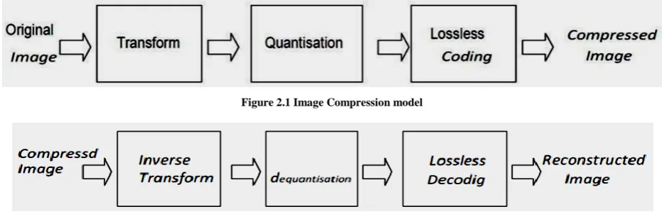
[image:2.595.64.530.427.578.2]Predictive versus Transform coding: In predictive coding, information already sent or available is used to predict future values, and the difference is coded. Since this is done in the image or spatial domain, it is relatively simple to implement and is readily adapted to local image characteristics. Differential Pulse Code Modulation (DPCM) is one particular example of predictive coding. Transform coding, on the other hand, first transforms the image from its spatial domain representation to a different type of representation using some well-known transform and then codes the transformed values (coefficients). This method provides greater data compression compared to predictive methods, although at the expense of greater computational requirements. Image compression basic model shown here in figure 2.1 and 2.2 consists of a Transformer, quantizer and encoder.
Figure 2.1 Image Compression model
Figure 2.2 Image Decompression model.
1. Transformer:
It transforms the input data into a format to reduce interpixel redundancies in the input image. Transform coding techniques use a reversible, linear mathematical transform to map the pixel values onto a set of coefficients, which are then quantized and encoded. The key factor behind the success of transform-based coding schemes is that many of the resulting coefficients for most natural images have small magnitudes and can be quantized without causing significant distortion in the decoded image.
For compression purpose, the higher the capability. of compressing information in fewer coefficients, the better the transform; for that reason, the Discrete Cosine Transform (DCT) and Discrete Wavelet Transform(DWT) have become the most widely used transform coding techniques.
(a) DCT:
International Journal of Emerging Technology and Advanced Engineering
Website: www.ijetae.com (ISSN 2250-2459, ISO 9001:2008 Certified Journal, Volume 7, Issue 9, September 2017)
399
The DCT transforms a signal from a spatial representation into a frequency representation. The DCT represent an image as a sum of sinusoids of varying magnitudes and frequencies. DCT has the property that, for a typical image most of the visually significant information about an image is concentrated in just few coefficients of DCT. After the computation of DCT coefficients, they are normalized according to a quantization table with different scales provided by the JPEG standard computed by psycho visual evidence. Selection of quantization table affects the entropy and compression ratio. The value of quantization is inversely proportional to quality of reconstructed image, better mean square error and better compression ratio.
In a lossy compression technique, during a step called Quantization, the less important frequencies are discarded, and then the most important frequencies that remain are used to retrieve the image in decomposition process. After quantization, quantized coefficients are rearranged in a zigzag order for further compressed by an efficient lossy coding algorithm.
(b) DWT:
Wavelets are a mathematical tool for changing the coordinate system in which we represent the signal to another domain that is best suited for compression. Wavelet based coding is more robust under transmission and decoding errors. Due to their inherent multiresolution nature, they are suitable for applications where scalability and tolerable degradation are important.
Wavelets are tool for decomposing signals such as images, into a hierarchy of increasing resolutions. The more resolution layers, the more detailed features of the image are shown. They are localized waves that drop to zero. They come from iteration of filters together with rescaling. Wavelet produces a natural multi resolution of every image, including the all-important edges. The output from the low pass channel is useful compression. Wavelet has an unconditional basis as a result the size of the wavelet coefficients drop off rapidly. The wavelet expansion coefficients represent a local component thereby making it easier to interpret. Wavelets are adjustable and hence can be designed to suit the individual applications. Its generation and calculation of DWT is well suited to the digital computer. They are only multiplications and additions in the calculations of wavelets, which are basic to a digital computer.
2. Quantizer:
It reduces the accuracy of the transformer’s output in accordance with some pre-established fidelity criterion. Reduces the psychovisual redundancies of the input image. This operation is not reversible and must be omitted if lossless compression is desired. The quantization stage is at the core of any lossy image encoding algorithm.
Quantization at the encoder side, means partitioning of the input data range into a smaller set of values. There are two main types of quantizers: scalar quantizers and vector quantizers. A scalar quantizer partitions the domain of input values into a smaller number of intervals. If the output intervals are equally spaced, which is the simplest way to do it, the process is called uniform scalar quantization; otherwise, for reasons usually related to minimization of total distortion, it is called non uniform scalar quantization. One of the most popular non uniform quantizers is the Lloyd Max quantizer. Vector quantization (VQ) techniques extend the basic principles of scalar quantization to multiple dimensions.
3. Symbol (entropy) encoder:
It creates a fixed or variable-length code to represent the quantizer’s output and maps the output in accordance with the code. In most cases, a variable-length code is used. An entropy encoder compresses the compressed values obtained by the quantizer to provide more efficient compression. Most important types of entropy encoders used in lossy image compression techniques are arithmetic encoder, huffman encoder and run-length encoder.
III. PROPOSED METHODOLOGY
Proposed work is based on lossy compression method using 8X8 DCT Coefficient Matrix. The lossy variant of JPEG consists of two parts: the encoder, which converts an RGB image into a JPEG stream, and the decoder, which converts the JPEG stream back into an RGB image. The standard does not specify how this stream is arranged in a file. This is subject to the file format’s specification, JPEG File Interchange Format (JFIF) being one of the most popular ones. In order to compress an image, various steps are executed, which is based on lossy compression. Figure 3.1 shows an overview of all involved in flow chart of proposed image compression method.
Step 1. Select Image for Compression.
Step 2. Load image into Matlab Environment.
Step 3. Calculate File Size.
Step 4. Convert Image into Double
Step 5. Calculate 8X8 DCM matrix.
Step 6 Convert Image into Double.
Step 7 Apply Block Processing on Image using 8X8 DCT
Matrix.
Step 8 Define Mask Matrix of 8X8 and block process on
previous stage output.
Step 9 Now reuse DCT operation to get O/P Image.
International Journal of Emerging Technology and Advanced Engineering
Website: www.ijetae.com (ISSN 2250-2459, ISO 9001:2008 Certified Journal, Volume 7, Issue 9, September 2017)
[image:4.595.55.536.117.755.2]400
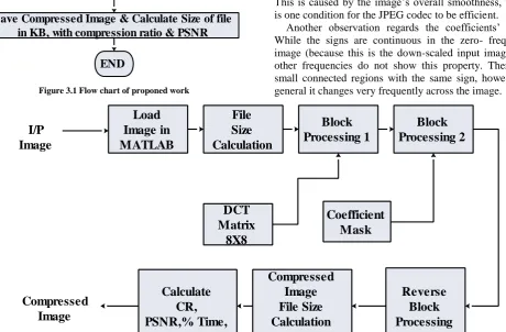
Figure 3.1 Flow chart of proponed workSelect the test image which is to be compress using function “uigetfile”. load the image into binary matrix or Matlab Environment. Calculate file Size in KB. and convert file in to type double. Now Apply block processing on images using 8X8 DCT Matrix. Define Mask Matrix of 8X8 and block process on previous stage output. 9 Now reuse DCT operation to get output Image Compressed image & calculate Size of the File in KB, with Compression ratio and PSNR. Block Diagram of proposed work has given in figure 3.2. And experimental outcome of proposed work has given chapter 4.1. Outcome of proposed work show the performance of the whole system on certain permits.
DCT is a special form of Fourier transform which decomposes a discrete real-valued function f:M^W into a sum of cosine functions of different frequencies. When the function’s domain consists of N elements, the re-composition After re-sampling, the image is split in blocks of 8x8 pixels and transformed into frequency space. This is performed using discrete cosine transform (DCT,
DCT’s lD-definition can be extended to two dimensions by applying 1D DCT to columns and rows after each other. For JPEG’s standard block size of 8x8 pixels, 2D-DCT.
It can be observed that the coefficient’s absolute values decrease as the frequencies that they represent increase. This is caused by the image’s overall smoothness, which is one condition for the JPEG codec to be efficient.
Another observation regards the coefficients’ signs. While the signs are continuous in the zero- frequency image (because this is the down-scaled input image), all other frequencies do not show this property. There are small connected regions with the same sign, however in general it changes very frequently across the image.
Figure 3.2 Block Diagram of proposed work.
Start
Select Image for Compression
Calculate File Size in kb
Convert Image into Double
Calculate 8X8 DCT Matrix
Apply Block Processing on Image using 8X8
DCT matrix
Define mask Matrix of 8X8 and block process on
previous stage o/p
Now Reuse DCT operation to get O/P Image
Save Compressed Image & Calculate Size of file
in KB, with compression ratio & PSNR
END
Load Image into MATLAB
Load
Image in
MATLAB
File
Size
Calculation
Block
Processing 1
Block
Processing 2
DCT
Matrix
8X8
Coefficient
Mask
Reverse
Block
Processing
Compressed
Image
File Size
Calculation
Calculate
CR,
PSNR,% Time,
Compressed
[image:4.595.62.523.437.739.2]International Journal of Emerging Technology and Advanced Engineering
Website: www.ijetae.com (ISSN 2250-2459, ISO 9001:2008 Certified Journal, Volume 7, Issue 9, September 2017)
401
Figure 3.2 illustrated the block diagram of proposed work. DCT the primary section of proposed work are as follows
Input Image, Block Processing 1 and block processing 2 coefficient matrix. Block processing as counted is connected with another reverse loop. The component id equipment to evaluate and calculate. Image files sizecalculation. Calculate CR Image compression and PSNR.
IV. EXPERIMENTAL RESULTS
[image:5.595.305.554.182.612.2]The implementation of proposed work has done on the MATLAB 13.1a. the outcome of proposed work has given in figure 4.1 Original Image with Dimension 425x318 and 15.34 Kbs. Fig. Compressed Image with Dimension 425x318 and 9.11 Kbs. its corresponding compressed image. Table 1 Comparison of Compression Ratio.
Fig. 4.1 Original Image with Dimension 425x318 and 15.34 Kbs.
Fig. 4.2 Compressed Image with Dimension 425x318 and 9.11 Kbs..
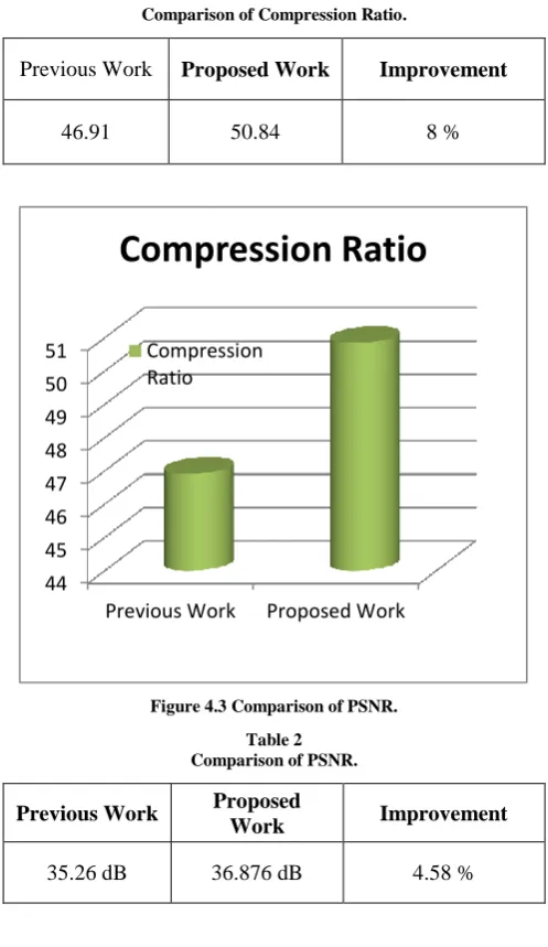
Table 4.1 has given comparison study of Prposed work with base work. graphical representation of table 4.1 ha given in figure 4.1.
Table 1
Comparison of Compression Ratio.
Previous Work Proposed Work Improvement
[image:5.595.51.282.340.512.2]46.91 50.84 8 %
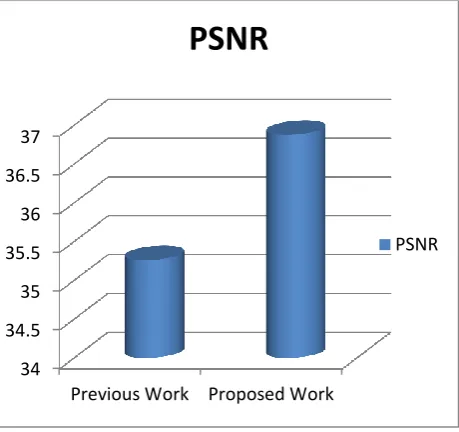
Figure 4.3 Comparison of PSNR.
Table 2 Comparison of PSNR.
Previous Work Proposed
Work Improvement
35.26 dB 36.876 dB 4.58 %
44 45 46 47 48 49 50 51
Previous Work Proposed Work
Compression Ratio
[image:5.595.52.282.536.710.2]International Journal of Emerging Technology and Advanced Engineering
Website: www.ijetae.com (ISSN 2250-2459, ISO 9001:2008 Certified Journal, Volume 7, Issue 9, September 2017)
[image:6.595.51.281.134.350.2]402
Figure 4.4 PSNR comparison.Table 4.2 has given Comparison of PSNR of Previous work with existing work. Graphical representation of table 4.4 has given in figure 4.2.
Table 3 Comparison of MSE.
Previous Work Proposed
Work Improvement
19.33 13.350 30.93 %
Table 3 has give Comparison of MSE of previous work vs proposed work and improvement in previous work.
[image:6.595.51.282.539.752.2]Graphical representation of proposed work has given in figure 4.5.
Figure 4.5 given Comparison of MSE of previous work vs. proposed work.
V. CONCLUSION
In the work image compression techniques using DCT are implemented in lossy compression domain. With the development of innovation and the entrance into the Digital Era, the world has ended up in the midst of a huge measure of data. Dealing with such enormous amount of information can often present difficulties. Digital data must be stored and retrieved in a productive way so as to put it to practical utilize a Lossy Compression utilizing 8x8 DCT Coefficient Matrix. There are other image sources that produce much higher information rates. Capacity and transmission of such information require huge limit and transfer speed, which could be costly. Image data weight system, worried about the decrease of the quantity of bits required to store or transmit image without any appreciable loss of data. Even if Discrete Cosine Transform is a widely adapted and robust method used for compression of digital image as it has the ability to carry the vast majority of the data in most modest number of pixels contrasted with other technique, the DCT Transform gave better outcome to the extent properties like RMS blunder, image power and execution time is concerned.
REFERENCES
[1] A. M. G. Hnesh and H. Demirel, "DWT-DCT-SVD based hybrid
lossy image compression technique," 2016 International Image Processing, Applications and Systems (IPAS), Hammamet, 2016, pp. 1-5. doi: 10.1109/IPAS.2016.7880068
[2] S. Afrose, S. Jahan and A. Chowdhury[2], "A hybrid
SVD-DWT-DCT based method for image compression and quality measurement of the compressed image," 2015 International
Conference on Electrical Engineering and Information
Communication Technology (ICEEICT), Dhaka, 2015, pp. 1-4. doi: 10.1109/ICEEICT.2015.7307442
[3] H. S. Prasantha, H. L. Shashidhara and K. N. B. Murthy[3], "Image
Compression Using SVD," International Conference on
Computational Intelligence and Multimedia Applications (ICCIMA 2007), Sivakasi, Tamil Nadu, 2007, pp. 143-145. doi: 10.1109/ICCIMA.2007.386
[4] S. Sebastian and Manimekalai M. A. P[4], "Color image
compression Using JPEG2000 with adaptive color space transform," 2014 International Conference on Electronics and CommunicationSystems(ICECS),Coimbatore,2014,pp.15.doi:10.11 09/ECS.2014.6892613.
[5] D. U. Shah and C. H. Vithlani, "FPGA realization of DA-based 2D-Discrete Wavelet Transform for the proposed image compression approach," 2011 Nirma University International Conference on Engineering, Ahmedabad, Gujarat, 2011, pp. 1-6.doi: 10.1109/NUiConE.2011.6153233.
[6] C. Vimalraj, S. S. Blessia and S. Esakkirajan, "Image compression
using wavelet packet and singular value decomposition," 2012 IEEE International Conference on Computational Intelligence and
Computing Research, Coimbatore, 2012, pp. 1-6. doi:
10.1109/ICCIC.2012.6510184
[7] A. J. Laub, Matrix Analysis for Scientists and Engineers, SIAM, 2005.
[8] R. C. Gonzalez and R. E. Woods, Digital Image Processing, 3 rd Edition, Prentice Hall, 2008.
34 34.5 35 35.5 36 36.5 37
Previous Work Proposed Work
PSNR
PSNR
0 5 10 15 20
Previous Work
Proposed Work