International Journal of Emerging Technology and Advanced Engineering
Website: www.ijetae.com (ISSN 2250-2459, ISO 9001:2008 Certified Journal, Volume 7, Issue 10, October 2017)
24
Dynamic Analysis of Shock Absorber Spring using Different
Materials
W. Shivaraj Singh
1, N. Srilatha
21MTech (CAD/CAM), 2Assistant Professor, VNR VJIET, Bachupally, Hyderabad 500090, India
Abstract— This paper is about the vehicle suspension system which connects a vehicle to its wheels and contributes to the vehicle's road handling and braking for better safety and driving pleasure, and offering a comfortable ride. It is important that the shock absorbers are efficient, durable and cost efficient. Material used for the helical coil spring is of great importance as it is one of the main part of suspension system. This paper deals with 3d modelling of shock absorber of a motorbike and performing dynamic analysis using ANSYS to determine its stress and deformation behaviour under time varying load and finally comparing strengths of different materials for the helical spring used. Damping effect due to the damper present is also considered during analysis to get more accurate results.
Keywords— ANSYS; dynamic analysis; helical spring; shock absorber
I. INTRODUCTION
Shock absorbers are an important part of any vehicular suspension system. A shock absorber absorbs shock and provides resistance to the movement of the spring. It does this by taking some of the energy that is being used to compress the spring and turning it into heat. So whether the vehicle is bouncing up or down from a bump in the road, that motion is held in check by the shock absorber, and once again some of the kinetic energy released by the spring is changed into heat by the shock absorber. This conversion of energy keeps the vehicle’s body from bouncing more than once or twice, providing a safe and controlled ride and helping to keep the vehicle’s tires safely in contact with the ground [1-4, 6-9,11].
A. Shock Absorbers
A suspension system supports weight of the vehicle. Its aim is to give a smooth ride on rough roads. Many vehicles have coil type springs in their suspension both in front and rear. Its disadvantage is excessive bouncing which makes shock absorber necessary. Vehicles while travelling hits a bump, the coil spring compresses. This compressed spring will try to return to its original length but will rebound past its original length which will lift the body. Again weight of vehicle will compress spring again and this bouncing repeats until it stops.
Bouncing is dangerous as it makes vehicle handling very difficult and also it makes the ride very uncomfortable. [1,16] It regulates the compression of spring by absorbing some energy when the spring is depressed. Some of the other applications of shock absorbers are:
• Many industrial machines
• Landing gear of aircrafts
• Buildings, bridges and other structures to make them
earthquake resistant
The main types of shock absorbers are:
• Pneumatic
• Hydraulic and
• Spring shock absorber
B. Methodology
The design of a helical spring is very important for the performance of a shock absorber and in whole, the suspension system [1]. [3] It has been described that a static spring may remain loaded for very long period of time. The failure modes of interest for static springs include spring relaxation, set and creep. The main objectives of spring are as follows:
• To apply force: A majority industrial, e.g. to provide the operating force in brakes and clutches, to provide a clamping force, to provide a return load, to keep rotational mechanisms in contact, make electrical contacts, counterbalance loading, etc.
• To control motion: Typically storing energy, e.g.
wind-up springs for motor, constant torque
applications, torsion control, position control, etc. • To control vibration: used in essence for noise and
vibration control, e.g. flexible couplings, isolation mounts, spring and dampers, etc.
International Journal of Emerging Technology and Advanced Engineering
Website: www.ijetae.com (ISSN 2250-2459, ISO 9001:2008 Certified Journal, Volume 7, Issue 10, October 2017)
25
Fig 1. (a) Helical spring with axial load (b) free body diagram
The specifications are given as [3]:
D= mean diameter of the coil spring
d= diameter of the wire n= number of active coil
p= pitch of the spring
F= axial load
G= Modulus of rigidity of spring material Lf= Free length of the spring
τ= Maximum shear stress
δ= Deflection of spring
The stiffness is given by the equation
As can be seen from the above equation, stiffness will change by changing the variables in the equation namely wire diameter, mean diameter of coil spring or number of active coils etc. To vary the stiffness of the spring for their analysis they all have varied the spring wire diameter by reducing the dimension [1,8,9]. The effect of reducing wire diameter is decrease in stiffness of the spring coil which in case of their research has performed well under the applied load. Speaking of loads, the shock absorber bears fluctuating loads as the vehicle travels on bumpy roads and
vibrations from various part of the vehicle.
II. LITERATURE REVIEW
Pinjarla Poornamohan, et al [1] in their paper “Design and Analysis of Shock Absorber” have mentioned that suspension system or shock absorber is a mechanical device designed to smooth out or damp shock impulse, and dissipate kinetic energy.3D modeling of a bike shock absorber is done using Pro-E software. Structural and modal analysis has been performed on the shock absorber using Ansys.
Analysis has been done on both the original design and a modified design where the spring wire diameter has been changed. Materials used for the spring are spring steel and beryllium copper. These has been done to determine the better material for the spring. Spring steel was found to perform better in terms of stress and deformation. Also, the modified design was found to perform better.
Sudarshan Martande et.al [2] have defined shock absorber as a critical part of vehicle suspension system. For this project they have performed structural analysis on each component of the shock absorber separately to find the stress and deformation under an applied load using Ansys software. The percentage error between analytic results and calculated results were determined and found to be within 15% which means the design is safe. (Sudarshan Martande et.al 2013) have only reviewed papers whose research were based on hydraulic shock absorber whereas their research is based on the helical spring used in shock absorber. Also, it was nowhere mentioned which materials were used in the analysis of the shock absorber. The complete steps in the calculation has also not been shown.
Niranjan Singh 2013 [3] The objective of his paper was to study the different types of springs used in vehicle suspension system. In this research paper, he has explained the different types of springs. Also, he has given the design concept of spring and mentioned that cost and materials, environmental factors, tolerances, working forces and deflections etc are some factors considered. The derivation for calculation of stresses in helical spring is given. Castigliano’s theorem is also briefly mentioned. Different materials that can be used to make different kind of springs are given along with their properties. This paper provides only the information regarding springs used in suspension.
Achyut P.Banginwar et.al 2014 [4] modeled a 3d design of a shock absorber using Pro-E and performed static structural and modal analysis. Load applied was the combined load of the vehicle and 1 person. It is assumed that 65% of total weight goes to the rear suspension and half of this goes to one of the two rear shock absorbers. Materials used for the helical spring were spring steel and phosphor bronze. Total deformation of spring steel was found to be less than phosphor bronze and natural frequency of spring steel greater than phosphor bronze. Thus spring steel was found to be the better material.
International Journal of Emerging Technology and Advanced Engineering
Website: www.ijetae.com (ISSN 2250-2459, ISO 9001:2008 Certified Journal, Volume 7, Issue 10, October 2017)
26
Visual observations found the wear scar on the upper surface of first active coil due to friction and contact. Scanning electron microscope was used and fatigue features and corrosion pits were observed. Stress analysis showed both shear stress and contact pressure exhibited singularities at the edges of contact zones which later led to crack nucleation. Close ended design of spring was blamed for the wearing out of coil surface, corrosion raised the local stress and promotes fatigue initiation and stress singularities further propagated by maximum principle stress and lastly failed due to overloading.
P.R Jadhav et. al 2014 [6] in their paper “Analysis of helical spring in mono-suspension system used in motorcycle” dealt with analysis of mono-suspension by using finite element approach and validated the results with analytic calculations with by varying the speed of the vehicle. Helical spring under the effect of uniform loading has been studied. Analysis is done by varying speed of bike at a bump of 50mm. Deflection and shear stresses are calculated using analytical equations. The deflection and shear stresses under applied load were found to increase as speed increases upto 10km/hr after which it starts decreasing. At higher speed it gives low deflection and low shear stresses.
G.R Chavhan et.al 2014 [7] in their paper “ Analysis of shock absorber using different material of spring” briefly explained about shock absorber and performed static and modal analysis on helical spring used in shock absorber in order to find the natural frequencies under vibration and the strength of the spring. Finding of frequencies is very important as springs in shock absorbers are constantly under the influence of fluctuating loads. So in order to avoid resonance and other factors, modal analysis is performed. The different material used were beryllium copper, carbon fiber and spring steel. Stress induced under load of 1 person and 2 persons were found to be high in carbon fiber as compared with beryllium copper and spring steel. Therefore, spring steel was found to be the best material among the three.
P.Karunakar et.al 2014 [8] in their paper “Comparative Design Analysis of Two Wheeler Shock Absorber” focused on using different materials for the coil spring used in shock absorbers i.e spring steel, Inconel X750,nickel 200. Modeling of the shock absorber was done in Creo software and analysis in Ansys. Load of the vehicle along with a single person was applied on the shock absorber during analysis to determine its stress and deformation behavior.
Stress under the applied load was found to be the least in Inconel X750 but the slight disadvantage was its higher cost compared to spring steel. So, material like Inconel is preferred in high end vehicles due to this reason.
Rahul Tekade et.al 2015 [9] in their paper “Structural and modal analysis of shock absorber of vehicle” used Pro-E to model the shock absorber in 3d and Ansys, to analyze the effect of load of the vehicle on the stress behavior of the shock absorber. Materials used were high carbon steel and spring steel. Stress of high carbon steel was found to be lesser compared to spring steel under same loading condition. Also, frequency of vibration was found to be higher in high carbon steel while performing modal analysis of the shock absorber. Therefore, it was concluded in the paper that high carbon steel is a better material than spring steel. (Rahul Tekade et.al 2015) haven’t specified the details of the shock absorber used in their work. Calculations are brief and not explained in details. Modifications done on the dimension of the shock absorber is just changing the diameter of wire spring. There is possibility of changing some other dimensions like number of pitch, mean diameter of coil etc.
Karthik A.S et al 2016 [10] “Design and static analysis of shock absorber” have only performed static structural analysis of shock absorber. They created a 3 dimensional model of a bike shock absorber using NX UNIGRAPHICS software and have done the analysis in Ansys by transferring the 3d model. Materials used were also different than what others have used before i.e structural steel, titanium alloy, copper alloy, aluminium alloy. After analysis, it was found that aluminium is best considering the cost factor along with lesser stress and deformation under the applied load. But performance wise titanium is better than aluminium. The only disadvantage of titanium alloy being its high cost. Even though copper is not as good as the former two materials, it was found to be better than structural steel.
III. 3D MODELLING
International Journal of Emerging Technology and Advanced Engineering
Website: www.ijetae.com (ISSN 2250-2459, ISO 9001:2008 Certified Journal, Volume 7, Issue 10, October 2017)
27
The helical spring used here is closed ended and ground. Closed ended springs can sometimes cause failure or fracture due to wearing out of protective coats [5] but closed and ground end springs offer better seating which also influences how the axial force produced by the spring is transferred to its mating part, or the mechanism that it works in. Buckling is reduced when the ends of the spring are closed and ground therefore it is a compromise that needs to be taken.
Fig 2. Yamaha TY175 bike
(a) (b) (c)
(d) (e) (f)
[image:4.612.153.544.168.695.2]
(g) (h) (i)
Fig 3. Parts made from aluminium 6082 T6 alloy.
(j) (k) (l)
(m)
Fig 4. Parts made from rubber
(n) (o) (p)
(q) (r)
Fig 5. Parts made from stainless steel
(s) (t)
[image:4.612.49.287.249.657.2]International Journal of Emerging Technology and Advanced Engineering
Website: www.ijetae.com (ISSN 2250-2459, ISO 9001:2008 Certified Journal, Volume 7, Issue 10, October 2017)
28
The parts are listed as follows:
a) Spring adjuster
b) Top mount
c) Body
d) Rod seal and bush holder
e) Bottom mount
f) Spring collet
g) Shim
h) Shim support
i) Piston
j) Bush
k) Rod seal
l) Piston ring
m) Bump stop
n) Washer
o) Lock ring
p) Hexagonal nut
q) Piston band
r) Piston rod
s) Outer spring
t) Inner spring
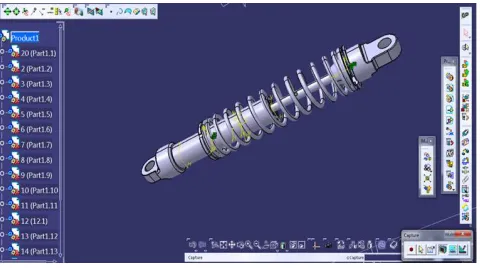
[image:5.612.50.290.506.640.2]The 3d model is created as per available dimensions in CATIA. After each required parts of the shock absorber has been modelled, it is assembled in CATIA assembly workbench to get the final completed shock absorber as shown below.
Fig 7. Shock absorber assembly
A. Design Calculations
For the analysis of shock absorber in ANSYS, certain input values are required which are calculated using necessary formulas and parametric values. The main value that needs to be calculated is the load to be applied on the shock absorber. This load should represent the load acting on the shock absorber in real life situation. For this we need to consider both the sprung mass and un-sprung mass of the vehicle in consideration and the weight of human driving the vehicle. In the papers [1, 2, 4, 7, 8, 11], they have all taken into account the load applied as the sum of the weight of the bike and the weight of 1 and (or) 2 persons. Out of this total weight 50-65 % is assumed to be applied on the rear suspension. Normally in two wheeler bikes since there are two shock absorbers at the rear wheel, this weight is divided by two. They have also considered dynamic loading as a result of which the load is doubled. It is explained below:
weight of bike= w
weight of 1 person=x
weight of 2 persons= 2x
rear suspension bears 60-65% of total weight, W
=50-65% of (w+x or w+2x)
single shock absorber =W/2
The vehicle is considered as having wet weight i.e fuel and other hydraulics are also present. The calculation is given below:
Weight of the bike, w = 87kg
Weight of an average human, x = 62kg
Total weight = 149kg
Weight bias for Yamaha TY175 = 46/54
54% of total weight is supported by rear suspension= 54% of 149 =80.46kg
= 789.3126N
The bike has two shock absorber at the rear therefore for single shock absorber, the load= 789.3126/2
International Journal of Emerging Technology and Advanced Engineering
Website: www.ijetae.com (ISSN 2250-2459, ISO 9001:2008 Certified Journal, Volume 7, Issue 10, October 2017)
29
B. Materials used and their propertiesTABLE I
Mechanical properties of materials used
s.n Material Density
(kg/m3)
Young’s modulus(GPa)
Poisson’s ratio
1 Spring steel
7850 210 0.29
2 Beryllium copper
8800 130 0.33
3 Aluminium 6082
2700 70 0.33
4 Rubber 1250 0.01 0.49
5 Stainless steel
8000 200 0.29
IV. MODAL ANALYSIS
Modal analysis is to determine the vibration characteristics (natural frequencies and mode shapes) of a structure or a machine component while it is being designed. It also can be a starting point for another, more detailed, dynamic analysis, such as a transient dynamic analysis, a harmonic response analysis, or a spectrum
analysis.ANSYS is the preferred software used by most of
the researchers. In the work done by [1, 4, 7], they have all performed modal analysis to find the natural frequencies and mode shapes. Detailed modal analysis determines the fundamental vibration mode shapes and corresponding frequencies. This can be relatively simple for basic components of a simple system, and extremely complicated when qualifying a complex mechanical device or a complicated structure exposed to periodic wind loading. These systems require accurate determination of natural frequencies and mode shapes using techniques such as Finite Element Analysis. This is also necessary to avoid resonance.
The main analysis to be performed here is transient dynamic analysis for which ANSYS is chosen. To come to that there is a need to first perform a modal analysis to find out the natural frequencies at different modes.
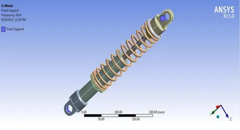
[image:6.612.325.564.180.309.2]The 3d cad model is converted to a proper format and transferred to ANSYS modal workbench. Modal analysis is performed by providing the necessary boundary conditions.
Fig 8. Fixed support in ANSYS for modal analysis
[image:6.612.324.556.378.507.2]The modal analysis is carried out for spring materials- spring steel and beryllium copper while keeping all other parts of same materials assigned. The results are given below
Table II Table III Frequencies for spring Frequencies for beryllium
Steel copper
International Journal of Emerging Technology and Advanced Engineering
Website: www.ijetae.com (ISSN 2250-2459, ISO 9001:2008 Certified Journal, Volume 7, Issue 10, October 2017)
30
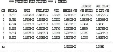
Table IV [image:7.612.48.272.331.435.2] [image:7.612.44.292.517.585.2]Participation factor for spring steel shock absorber
Table V
Participation factor for beryllium copper shock absorber
From the participation factor tables, it can be said that the most dominant frequencies for the spring materials are
the 3rd mode frequency.
Table VI Dominant frequencies
s.no Materials Resonant
frequency
1 Spring steel 65.17 Hz
2 Beryllium copper 47.87 Hz
A. Time step calculations
The time step to be used for the transient dynamic analysis is calculated from the frequencies such that it includes the most dominant frequency and it should be able to capture the dynamic behaviour of the shock absorber. The time step is calculated from the equation:
(ii)
For spring steel
For beryllium copper
The time steps entered during settings for transient analysis should include these time steps. The more the time steps the more time it takes for simulation. But it gives more accurate results. The aim is to find an optimum time step.
B. Damping coefficient calculation
The presence of damper in the shock absorber means that damping is present. This damping helps to decrease vibration by converting the kinetic energy of the spring into heat and dissipating it. This makes the spring to bounce less and return to equilibrium as soon as possible.
(iii)
where ζi = damping ratio ωi = dominant frequency
The damping ratio for passenger vehicles is mostly 0.25 but for off-road vehicles it is taken in the range of 0.2-0.7 [11,12,15]. Transient dynamic analysis is to be done at two different damping ratio of 0.2 and 0.7 to study its effect on deformation and stress.
For spring steel at damping ratio of 0.2 and 0.7
International Journal of Emerging Technology and Advanced Engineering
Website: www.ijetae.com (ISSN 2250-2459, ISO 9001:2008 Certified Journal, Volume 7, Issue 10, October 2017)
[image:8.612.323.564.139.245.2]31
Table VIIDamping coefficient for different spring materials at 0.2 and 0.7 damping ratio
S.no Spring
materials
Damping ratio
Damping coefficient
1 Spring steel 0.2 0.0009
0.7 0.003
2 Beryllium
copper
0.2 0.001
0.7 0.004
V. TRANSIENT DYNAMIC ANALYSIS
Transient dynamic analysis is a technique used to determine the dynamic response of a structure under a time-varying load.
The time frame for this type of analysis is such that inertia or damping effects of the structure are considered to be important. Cases where such effects play a major role are under step or impulse loading conditions, for example, where there is a sharp load change in a fraction of time.
If inertia effects are negligible for the loading conditions being considered, a static analysis may be used instead.
The basic equation of motion solved by a transient dynamic analysis is
(iv) where:
[M] = mass matrix [C] = damping matrix [K] = stiffness matrix ü = nodal acceleration vector ů = nodal velocity vector {u}= nodal displacement vector {F(t)} = load vector
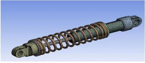
[image:8.612.58.279.171.260.2]The mass, stiffness and damping factor are changing as the materials are changed and the damping coefficient are varied. Transient analysis will find out how this will affect the stress and deformation behaviour of the shock absorber. Before starting analysis in connection section, define appropriate connection between parts according to the part’s behaviour. Connection can be either “contact” or “joints” or “contact + joints” based on the real word application of the product. Joints used in this project are fixed joints and translational joint for the movement of the piston rod inside the body. Also proper meshing is to be provided such that it takes lesser computational time as well as the results are accurate enough. For this multiple simulations have to be run using different meshing sizes.
Fig 9. Meshing done for transient analysis
After meshing has been done, the time steps and damping coefficient calculated earlier are entered in the analysis settings section. For each spring material, two simulations are done for 0.2 and 0.7 damping ratio i.e 4 simulations in total.
A. Dynamic analysis for spring steel spring shock absorber
The load of 394.65N calculated before is applied in the analysis settings along with the time steps and damping coefficient and simulation is carried out each time changing the spring material to spring steel and beryllium copper. Directional deformation and shear stress are found out from the analysis for each spring material at 0.2 and 0.7 damping ratios.
Spring steel at 0.2 damping ratio
Fig 10. Directional deformation for spring steel at 0.2 damping ratio
[image:8.612.324.562.444.538.2] [image:8.612.324.564.566.662.2]International Journal of Emerging Technology and Advanced Engineering
Website: www.ijetae.com (ISSN 2250-2459, ISO 9001:2008 Certified Journal, Volume 7, Issue 10, October 2017)
[image:9.612.324.562.137.246.2]32
Spring steel at 0.7 damping ratio [image:9.612.46.288.157.253.2]Fig 12. Directional deformation for spring steel at 0.7 damping ratio
Fig 13. Shear stress for spring steel at 0.7 damping ratio
[image:9.612.325.563.273.365.2]Beryllium copper at 0.2 damping ratio
Fig 14. Directional deformation for beryllium copper at 0.2 damping ratio
Fig 15. Shear stress for beryllium copper at 0.2 damping ratio
Beryllium copper at 0.7 damping ratio
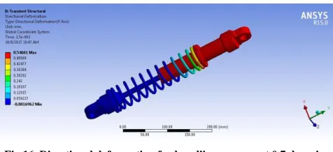
Fig 16. Directional deformation for beryllium copper at 0.7 damping ratio
Fig 17. Shear stress for beryllium copper at 0.7 damping ratio
The directional deformation is to account for spring deformation in direction of applied load and shear stress in XY plane to account for shear stress in y direction in XY plane
VI. RESULTS
[image:9.612.48.288.276.380.2] [image:9.612.45.288.410.496.2]The results from the transient analysis are given in the table below:
Table VIII
Deformation and shear stress results
Cases Material Damp. Factor
Max Dir.
Deformation (mm)
Max. XY Plane
Shear Stress
(MPa)
1-1 Spring Steel 0.2 0.63 44.52
1-2 0.7 0.52 36.41
2-1 Beryllium Copper
0.2 0.65 29.26
[image:9.612.326.566.511.704.2] [image:9.612.47.288.530.614.2]International Journal of Emerging Technology and Advanced Engineering
Website: www.ijetae.com (ISSN 2250-2459, ISO 9001:2008 Certified Journal, Volume 7, Issue 10, October 2017)
33
From the results, it can be seen that deformation for spring steel is the lesser in case of 0.7 damping ratio. Shear stress is lesser for 0.7 damping. For beryllium copper spring shock absorber also, it shows similar pattern. Let’s compare some other factors to decide which material is better. The energy storing capacity of spring steel is much larger than that of beryllium copper as the energy stored is given by:
Where k=stiffness
x=deflection of spring K for spring steel is 9332.32 N/m K for beryllium copper is 5530.26 N/m
Therefore, for the same amount of deflection x, the energy stored would be higher in spring steel spring as stiffness is higher.
Now let us compare the strength to weight ratio for both materials.
For spring steel, specific strength= ultimate tensile strength/density
=1700MPa/7.850g/cc =216.56 KN-m/kg
For beryllium copper, specific strength
=1380MPa/8.8g/cc =156.81 KN-m/kg
The strength to weight ratio for spring steel used is also better than beryllium copper.
Also the shear strength of spring steel is 1378 MPa and that of beryllium copper is 780 MPa. Therefore, the shear stress is way below the shear strengths of each spring material and they can take the stress developed.
VII. CONCLUSION
The conclusion drawn from this analysis are that the resonant frequency of the shock absorber changes with change in material of the spring. It is to be made sure that the frequency of any major part of the vehicle which produces large vibration should not match with this resonant frequency. Directional deformation and shear stress are lesser in spring steel with 0.7 damping than with 0.2 damping. Similarly, directional deformation and shear stress are lesser for 0.7 damping ratio in case of beryllium copper spring. Damping changes the deformation and shear stress values.
Increase in damping decreases the deformation and shear stresses. Deformation and shear stress results are not related as their governing equation are different. Deformation is lesser in spring steel shock absorber as it is stiffer compared to beryllium copper spring.
A suitable damping coefficient should be employed keeping in mind the requirements of the vehicle and rider.
The energy storing capacity of the spring steel spring is better than that of beryllium copper. The strength to weight ratio of spring steel is also better which means it has more strength and is also lighter in weight compared to beryllium copper spring. This is very useful in case of vehicles where weight is a main concern. It is also cheaper than beryllium copper. It is less corrosion resistant compared to beryllium copper but that can be taken care of by many corrosion prevention techniques. The future scope of spring material research will be to find a stronger and more lightweight material.
REFERENCES
[1] Pinjarla Poornamohan, Lakshmana Kishore T, “Design and Analysis of Shock Absorber,” IJRET, vol. 1, no. 4, ISSN. 2319-1163, Dec, 2012.
[2] Sudarshan Martande,Y.N Jangale,N.S Motgi, “Design and Analysis of shock absorber,” IJAIEM, vol 2, no. 3, ISSN. 2319-4847, March,2013.
[3] Niranjan Singh, “General Review of Mechanical Springs used in Suspension Sytem,” IJAERS, studies/3/1, ISSN 2249-8974, Oct-Dec,2013
[4] Achyut P.Banginwar, Nitin D.Bhusale, Kautuk V.Totawar, “Design and Analysis of Shock Absorber using Finite element analysis tool,” IJERD, vol. 10, Issue 2, pp. 22-28, Feb. 2014.
[5] Youli Zhu, Yanli Wang, Yunalin Huang, “Failure Analysis of Helical Compression Spring For Heavy Vehicle’s Suspension Sytem,” Case studies in Engineering Failure Analysis 2, Elsevier,169-173, June,2014
[6] P.R Jadhav, N.P Doshi, U.D Gulhane, “Analysis of Helical Spring in Mono-suspension System used in Motorcycle,” IJRAT, vol 2, Issue 10,ISSN 2321-9637,Oct,2014.
[7] G.R Chavhan, S.W Burande, L.P.Dhole, “Analysis of Shock Absorber using different material of spring,” IJAET, vol 5, Issue 4,ISSN 0976-3945,Dec,2014.
[8] P.Karunakar, P. Varalaxmi, Ch. Rohit R. Reddy, “Comparative Design Analysis of Two Wheeler,” ICIEMS, ISBN 978-81, 2014 [9] Rahul Tekade, Chinmay Patil, “Structural and Modal Analysis of
Shock Absorber of Vehicle,” IJETT, vol 21, no.4, ISSN 2231-5381, Mar,2015
[10] Karthik A.S, Manojkumar M.Hanumanalli, Vinaykumar B. Honakeri, Manjunath S, “Design and Static Analysis of Shock Absorber,” IJIRST, vol 2, no 12, ISSn 2349-6010, May, 2016 [11] Vittore Cossalter, 2006, chapter-5 Inplane dynamics, “Motorcycle
Dynamics” ,2nd edition, LuLu, pp-184-187
International Journal of Emerging Technology and Advanced Engineering
Website: www.ijetae.com (ISSN 2250-2459, ISO 9001:2008 Certified Journal, Volume 7, Issue 10, October 2017)
34
[13] Satbeer Bhatia, Ajeet Bergaley, “Analysis of helical compressionspring”, IJESRT, vol 3 no 8, ISSN 2277-9655, Aug, 2014 [14] http://engineerjau.wordpress.com/2013/05/11/understanding-the
mass-participation-factor/
[15] http://www.shimrestackor.com/phsics/spring_mass_damper/htm [16] US Army Ordnance Center and School, “Wheeled vehicles, drive