Interoperability specification development
for integrated BIM use in performance
based design
Arayici, Y, Fernando, TP, Munoz, V and Bassanino, MN
http://dx.doi.org/10.1016/j.autcon.2017.10.018
Title Interoperability specification development for integrated BIM use in performance based design
Authors Arayici, Y, Fernando, TP, Munoz, V and Bassanino, MN
Type Article
URL This version is available at: http://usir.salford.ac.uk/id/eprint/44188/ Published Date 2017
USIR is a digital collection of the research output of the University of Salford. Where copyright permits, full text material held in the repository is made freely available online and can be read, downloaded and copied for noncommercial private study or research purposes. Please check the manuscript for any further copyright restrictions.
1
Interoperability Specification Development for Integrated BIM Use in
1Performance Based Design
2Abstract: Interoperability in BIM is low and the focus is on 3D coordination. Despite the 3
available standards including IFC and IDM, there is still no clear guidance how such standards 4
can be effectively used for performance based design. Thus, early collaboration is discouraged 5
and performance analysis is conducted as late as possible to minimize the number of information 6
exchanges, leading to difficulties and costly changes in design that is almost completed. 7
Aim is to propose an interoperability specification development approach for performance based 8
design through the Design4Energy case study project. Findings show that the design process had 9
increased flexibility, shared understanding between stakeholders about what information nuggets 10
should be provided from whom to whom, at what stage, using which tool and data model. 11
It can guide for the integrated BIM practice and help developing BIM execution plans for Level 12
2 BIM while paving the way for Level 3 BIM. 13
Keywords: Energy efficiency, performance based design, interoperability, Building Information 14
Modelling, Information Delivery Manual, Model View Definition, Design4Energy 15
1. Introduction 16
Digital tools are used in the architecture, engineering and construction (AEC) industry for the 17
last 30 years. Nonetheless, the attention of the industry has been captured strongly in recent years 18
by the irruption of new tools and methods for improving information management over the 19
project lifecycle (Hetherington et al, 2010). The most important of these contemporary trends is 20
Building Information Modelling (BIM), which encapsulates a group of tools, processes and 21
technologies able to manage information for a building, its performance, planning and operation 22
(Eastman et al., 2011; Arayici, 2015). 23
There is a consensus in the literature about the need to achieve performance based design via 24
Integrated BIM use (Paryudi, (2015; Krygiel & Nies, 2008; Hemsath, 2015; Levy, 2012; Jeong 25
and Kim, 2016). Building Performance Simulation (BPS) for performance based design is an 26
area allowing the architect to create and explore different design alternatives and to select the 27
lower energy consumption alternatives. Unfortunately, the full potential of BPS has not been 28
achieved yet because of a lack of integration that prevents collaborative relationships among 29
team members throughout the project lifecycle (Jeong and Kim, 2016; Wong et al, 2014; Aouad
30
and Arayici, 2010; Deutsch, 2011). This is due to lack of clear guidance or low level of BIM use. 31
Mainly, BIM use in practice is at Level 1 and rarely at Level 2. As consequence of low level of 32
BIM use and lack of integration, designers are only using BPS tools to check energy codes after 33
the design is mostly finished, instead of using it to support early design decisions to improve the 34
energy performance (Eastman et al., 2011; Jeong and Kim, 2016). 35
Many building performance simulation (BPS) tools to support stakeholders ‘decision-making 36
2
design professionals and practitioners to analyse and evaluate their building projects (Arayici, 38
2015). Traditionally, architects and engineers have found it difficult to effectively use BPS tools 39
because their processes are based on 2D manually-created drawings. This characteristic is 40
necessitated by the lack of integration among the tools and between design models and building 41
energy models ((Jeong and Kim 2016). 42
Based on literature, the energy simulation tools are not architect friendly and they are too 43
complex for the architects besides the tools are not compatible with architects’ working methods 44
and needs (Paryudi, 2015; Jeong and Kim, 2016). This fact causes the limited benefits from the 45
energy simulation tools by architects during early design stage. Not to mention is another fact 46
that architects are novices in the energy simulation field. Therefore, they lack simulation know-47
how (Paryudi, 2015). This weakness impedes architects from using energy simulation tools 48
regularly, leading to the most architects preferring simple energy simulation tools without 49
collaboration (Jeong and Kim, 2016; Asmi et al, 2015) even though it is critical for performance 50
based design. 51
The major issue with the implementation of performance based design is how effectively 52
integrate different technologies that exist across multiple domains and provide comprehensive 53
building performance analyses in the design process in a collaborative manner. For instance, the 54
main concern with solar building design is how to integrate different technologies (e.g., building-55
integrated photovoltaic, solar thermal, and daylighting) into a coherent combination and 56
effectively use those diverse tools and data for building performance analysis during the design 57
phase (Jeong and Kim 2016). Therefore, a holistic and integrated approach to performance based 58
design is needed to efficiently provide energy performance analysis based upon multiple domain 59
simulations with a lifecycle perspective at the early design phase. Such an integrated building 60
performance analysis would require the integration of the multi-domain actors (Jeong and Kim 61
2016; Arayici, 2015), including client, architect, facility managers and energy experts. 62
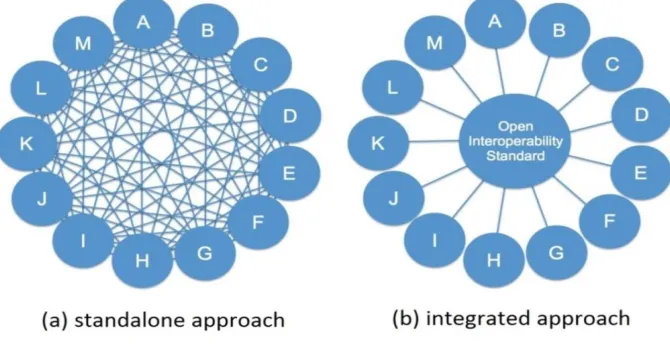
Currently, the design integration is addressed in two ways: the standalone approach and the 63
integrated approach. In the standalone approach (Figure 1a) all the actors are working together 64
on the same platform, while they can still use different software to create their own data that will 65
be readable by the other users that have access to the same platform. However, this approach is 66
not applicable to a whole project because there is not a single platform that is able to support the 67
data created across the whole lifecycle of a project. Thus, it will be necessary to use other tools 68
to add different data (Smith & Tardiff, 2009; Laakso & Kiviniemi, 2012). 69
On the other hand, the integrated approach (Figure 1b) uses a translator tool to convert the 70
proprietary format into open data readable by any software that supports this standard (Eastman 71
et al., 2011; Elvin, 2007). Using an open standard facilitates the collaborative work allowing any 72
actor to exchange data with any other specialists no matter what the software was in which the 73
data was created (Smith & Tardiff, 2009). The issue of interoperability is present in a lot of areas 74
if collaboration, interaction and data exchange are needed. This is particularly true of the AEC 75
3
uptake of the Building Information Modelling (BIM) paradigm have intensified the need for 77
collaboration between different stakeholders across many disciplines throughout the entire 78
building life-cycle (Asmi et al 2015; Jeong and Kim, 2016). 79
[image:4.612.138.473.133.307.2]80
Figure 1: Information exchange view (Laakso & Kiviniemi, 2012) 81
The integration via open standards is critical in providing the information exchange throughout 82
the AEC/FM project lifecycle; nonetheless the open standards need to be improved to ensure a 83
correct data exchange no matter what tool is used to produce or read the data (Kymell, 2008). 84
Currently, the integration for BIM models is addressed using two formats: Industry Foundation 85
Classes (IFC) and green building XML (gbXML). The IFC format is a schema widely accepted 86
by the AEC industry to exchange BIM models. It uses four layers (resources, core, 87
interoperability and domain) to describe the geometry information, the material properties and 88
the relationships in a BIM model (Smith & Tardiff, 2009). The gbXML schema facilitates the 89
exchange of data between BIM and BPS tools (Jeong and Kim, 2016). 90
Despite both formats being used by the AEC industry, its adoption does not ensure a data 91
exchange free of problems. The IFC schema does not capture the ways how information is 92
created and shared by practitioners (Weise et al., 2009; Asmi et al 2015). In other words, what 93
specific information at what granularity should be included in the exchange cannot be 94
automatically invoked by the IFC schema unless there is a clear procedure and shared 95
understanding amongst the actors about what information nuggets should be encapsulated in the 96
IFC schema. Otherwise, some specific information will be missed in the exchange process (Juan 97
& Zheng, 2014; Weise et al., 2009). On the other hand, the gbXML format is not mature enough 98
and has been limited to being used in simple design solutions because of its inability to read 99
complex geometries (Bahar et al., 2013). 100
Thus, the emergence of standard BIM data formats does not, however, brings a definitive 101
solution to the interoperability issue (Asmi et al 2015) without a clear guidance or specification 102
of information sharing for the Integrated BIM use for performance based design. Therefore, this 103
paper provides a practical approach for how interoperability can be formulated for performance 104
4
project case study where an interoperability specification is developed and executed for the 106
Integrated BIM practice for performance based design. 107
2. The Design4Energy Project 108
The Design4Energy (D4E) research project, funded by the European Union (EU) under the 7th 109
Framework Programme (FP7), aimed to develop an innovative and integrated design 110
methodology to predict the current and future energy demand of buildings (both at the individual 111
and neighbourhood level). Predicting energy consumption would allow operators to manage 112
demand to off-peak times, to reduce the energy costs, to minimise outage frequency and duration 113
and to simplify the interfacing of renewable energy sources with the system decreasing the 114
carbon liabilities (Azhar et al, 2011). 115
The design methodology proposed by the D4E project asks for early collaboration, integrated 116
processes and stakeholders with the objective of supporting informed decisions to optimise the 117
energy performance at building life cycle level including operation and maintenance. A key point 118
in the success of the project is the monitoring of the carbon dioxide emissions (CO2) of buildings
119
to ensure that the design criteria are met in practice and to collect data that enable the better 120
decisions making (Motawa & Carter, 2013). Therefore, it is necessary to describe the 121
information exchange that will allow a smooth information flow between applications. 122
What are observed and experienced in the Design4Energy project have also confirmed what is 123
reviewed and said in the literature. There were architects from Spain, UK and Germany and 124
energy experts and engineers from Finland and Portugal. There was no coherent understanding 125
between them about how BIM based collaborative design can be possible and information 126
sharing and exchange can be executed using available standards such as IFC for performance 127
based design development and beyond. Simply architects can do BIM modelling but they had no 128
understanding of what information and when they should share any relevant information with the 129
client and energy experts. This was indicating that there was a need to develop an 130
interoperability specification that would coherently picture the collaborative design process to be 131
executed amongst themselves. Furthermore, similar confusion and lack of understanding 132
amongst the technical team even though they were all expert in BIM and offered various BIM 133
tools developments for data modelling and filtering, interoperability execution for the integrated 134
BIM practice. Therefore, it was needed to develop an interoperability specification that would 135
pull all the patches together into a coherent picture by addressing human, process, technology 136
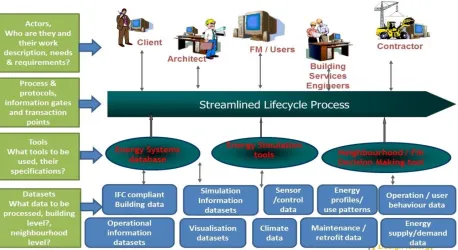
and data aspects for the Integrated BIM practice. Figure 2 shows the scope of the interoperability 137
specification required in the project. 138
It defines the interoperation between the various systems such as the IFC-based BIM 139
components library, the BIM information filtering system, the BIM authoring tools, the 140
performance simulation tools, the decision support tools for early design and retrofit planning 141
and the Collaborative Virtual Design Workspace running across the cross-organizational 142
5 144
Figure 2: Interoperability vision for the Design4Energy Collaborative Workspace 145
The interoperability specification should clearly describe how the user requirements and needs, 146
tasks and activities for the performance based design can be coherently dealt with by the various 147
stakeholders using different BIM tools and technologies. The next section explains the research 148
methodology for the development of the interoperability specification 149
3. Research Methodology 150
This paper aims at developing an interoperability specification to promote early collaboration in 151
looking at energy simulations in addition to predicting current and future energy demand and the 152
impact of such demands upon carbon emissions. Because such an approach does not exist in the 153
literature (Motawa & Carter, 2013; Paryudi, 2015), the research methodology needs to support 154
the development of new knowledge in the area where the existing theory is insufficient. Thus, 155
this paper adopts the Design Science Research (DSR) methodology, which facilitates the spread 156
of new ideas through the use of models, methods, constructs, instantiations and theories (Hevner 157
and Chatterjee, 2010), social innovations, new or previously unknown properties of 158
technical/social/informational resources, new explanatory theories, new design and development 159
models and implementation processes or methods (Ellis & Levy, 2009). The DSR methodology 160
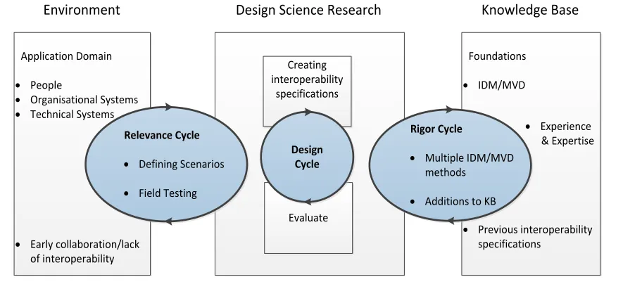
uses the cycles below to create new knowledge (Figure 3): 161
- Relevance cycle: this first cycle explains the application domain, in which the research will 162
take place. Defining the application domain will need the identification of the research 163
requirements such as the problem/opportunity to be addressed, the people involved and the 164
organisational and technical systems that interact towards achieving the goal. The research 165
6
problem. This specification will be tested and the result will indicate whether additional 167
iteration of the relevance cycle is needed (Peffers et al, 2012). 168
Application Domain
· People
· Organisational Systems
· Technical Systems
· Early collaboration/lack of interoperability
Environment Design Science Research Knowledge Base
Creating interoperability
specifications
Evaluate
Design Cycle Relevance Cycle
· Defining Scenarios
· Field Testing
Foundations
· IDM/MVD
· Previous interoperability specifications
· Experience & Expertise
Rigor Cycle
· Multiple IDM/MVD methods
· Additions to KB
[image:7.612.85.541.110.312.2]169
Figure 3: DSR oriented research methodology of the paper
170
- Rigor cycle: This cycle will create the foundations, in which the research will be based, 171
ensuring that the research contains new knowledge and that it is not routine design based in a 172
well-known process. The knowledge base will take elements from scientific theories, methods 173
and previous experiences (Peffers et al, 2012). 174
- Design cycle: In this cycle, most of the DSR is undertaken. The research artefacts coming 175
from the relevance cycle are built and evaluated. Based on the results from this cycle, it will 176
be possible to modify the specification until achieving the requirements set in the relevance 177
cycle. Knowledge gained in this cycle will be added in the rigor cycle to improve the 178
foundations of the research (Peffers et al, 2012). 179
In this research, the relevance cycle will capture a sequence of expert activities. These data are 180
described by the application domain (Figure 3) identifying people (who), organisational systems 181
(how) and technical systems (what), which are involved in the problem. Understanding the 182
context of the research will deliver a better grasp of the interoperability challenges and problems 183
in different the design scenarios. On the other hand, the knowledge base will be built on 184
IDM/MVD. The knowledge generated is used to develop the interoperability specification for the 185
design scenarios from the application domain. Evaluation of completeness and efficacy of the
186
interoperability specification is demonstrated via phases from the parent processes (Figure 4).
187
3.1. Relevance cycle (Application domain) 188
Figure 2 introduced the interoperability scope envisioned for the Design4Energy research 189
project. Based on that, it is possible to state that the specification to be developed must show the 190
user requirements, tasks and activities through the different life cycle stages and must also show 191
7
the multiple elements throughout the lifecycle, it is required to develop an integrated process that 193
provides a coherent picture of performance based design practice. The process will need to 194
define hierarchic levels to divide the entire process into small sections and facilitate the 195
interoperability development as shown in Figure 4 (Wix et al, 2009; Eastman et al, 2010). 196
DATA TASK TASK Phase 1
Scenario 1 / Process
DATA TASK TASK Phase 2
Scenario 2 / Process
DATA TASK TASK Phase 3
Parent process
[image:8.612.130.493.144.295.2]197
Figure 4: Hierarchy levels for cross-organisational business processes 198
- Parent process: a process that contains sub processes within its boundaries.
199
- Scenario/process: a sequence of activities in an organisation with the objective of carrying
200
out work.
201
- Phase or Stage: a period in the duration of a project identified by the overall character of the
202
tasks which occur within it.
203
- Task: an atomic activity that is included within a process.
204
- Data: a mechanism to show how data is required or produced by tasks. 205
Based on the scope of the interoperability (Figure 2) and the hierarchy levels (Figure 4), three 206
scenarios were developed in the Design4Energy project to comprise user activities, user 207
requirements and the functional requirements of the key stakeholders such as the client, the 208
architect, the energy expert and the HVAC designer. These scenarios are: 209
· Scenario 1: district energy trading context in building design: This scenario illustrates 210
how an energy efficient building or a group of buildings and its neighbourhood can be 211
analysed and holistically optimised throughout the whole life cycle. This is performed by 212
using an appropriate supportive technology platform during the design phase and the 213
adaptation of new business models to overcome current limitations. 214
· Scenario 2: holistic design for energy optimisation: Focusing on a new build, the scenario 215
illustrates how advanced simulation tools and modelling techniques can improve current 216
practice at an early design phase. Through this scenario, multi-disciplinary design teams can 217
explore various energy design solutions collectively and individually in an interactive virtual 218
workspace to achieve optimum energy efficiency at a building level. 219
· Scenario 3: use of operational and maintenance data in retrofit: This scenario illustrates 220
how members of the design team can simulate and evaluate design retrofit alternatives based 221
8
Each of the scenarios corresponds various phases of the building life cycle (Figure 5): 223
31 10 11 00: Needs Identification and 31 10 41 44:
Feasibility Stage:
Theme: Design Requirements, Neighbourhood & Feasibility
31 20 10 14: Concept Design Stage: Sketching New Design:
Theme: Early Design Modelling, Environmental Analysis, Building Performance
Assessment
31 20 10 14: Concept Design Stage: Sketching New
Design:
Theme: Design Check and Energy Matching
31 20 20 11: Detail Design
Stage:
Theme: Detail Design & Optimisation
31 20 20 14: Final Design
Stage: Theme: Integrated Design Review
31 40 40 14: Project Execution and 31 80 00 00: Handover
Stages:
Theme: Construction (Out of Project Scope)
31 80 00 00: Use and Operation
Stage:
Theme: Defining the Need for
Retrofit/ Maintenance
31 80 00 00: Use and Operation Stage: Theme: Retrofit/ Maintenance Modelling and Decision Making 224
Figure 5: Integrated Building Lifecycle Processes with scenarios and Omniclass classification 225
- Scenario 1: contains the needs’ identification and feasibility phases. During these phases, the 226
design requirements, neighbourhood and feasibility studies are developed. 227
- Scenario 2: includes the concept design, the detailed design and the final design phases. The 228
concept design phase develops early design modelling, an environmental analysis, a building 229
performance assessment, a design check and energy matching. The detailed design phase will 230
optimise the design. The final design phase will integrate the design for a review. 231
The construction execution phase is outside the current project’s scope. 232
- Scenario 3: considers the BIM handover and facility management (operation) phase, 233
including defining the needs for retrofit or maintenance, retrofit modelling, environmental 234
analysis, building performance assessment, retrofit check and energy matching for 235
maintenance. 236
In the research, the interoperability specification is developed for the whole building life cycle 237
process encapsulating these three scenarios. However, in this paper, the interoperability 238
specification development for scenario 2 is explained as it is succinct enough to demonstrate how 239
the interoperability specification is developed including soft and hard aspects shown in Figure 2. 240
3.2. Rigor cycle (Knowledge Base: Information Delivery Manual (IDM) & 241
Model View Definition (MVD)) 242
The industry has addressed the interoperability issue utilising multiple initiatives. A glance at the 243
literature might be confusing because of the number of organisations that have, over recent years, 244
developed standards in this field (Smith and Tardiff, 2009; Pinheiro et al 2015). For example, 245
two BuildingSmart initiatives to tackle interoperability issues are Information Delivery Manual 246
9
2015). The objective of both methods is to develop interoperability, yet from a different point of 248
view; while IDM defines interoperability at user level capturing processes and exchange 249
requirements (Pinheiro et al, 2015; Eastman et al, 2010), MVD sets interoperability at a technical 250
level defining specific IFC configurations (Asmi et al, 2015). 251
Both IDM and MVD methods have been amalgamated into a combined one and called “An 252
integrated process for delivering IFC based data exchange” by BuildingSmart. It starts with the 253
user requirements’ capture for exchanges using the IDM methodology. It is then translated into 254
technical schema such as the IFC schema via the MVD method. However, this procedure brings 255
problems relating to the blurred boundaries between IDM and MVD in assigning the users the 256
responsibility for developing a technical solution such as exchange requirement models. In other 257
words, the lack of requirement rationalization can lead to the incurrence of similar exchange 258
models, which need to be reduced to avoid the number of repetitiveness in MVD modelling. For 259
example, a BIM model improves progressively throughout the design process phases, in which 260
the same information exchange model can be shared more than once even if the values would be 261
different in each exchange. Therefore, it is critical to identify the repetitive exchanges of the 262
same BIM model information in the development of the MVD based technical schema. This 263
would help to: 264
· make information exchanges between project participants more reliable. 265
· improve information quality. 266
· improve decision making. 267
· undertake a BIM project far more effectively. 268
The steps in the IDM method for the interoperability specification development include process 269
modelling, information exchange and functional parts. Both IDM and MVD are explained in the 270
following sections on the Early Design Modelling, Environmental Analysis, Building 271
Performance Assessment themes in the DesignCheck&EnergyMatching Process Phase in Figure 272
5. 273
3.2.1. Information Delivery Model (IDM) 274
IDM (ISO, 2016) proposes a systemic method to capture (and progressively integrate) business 275
processes whilst, at the same time, providing detailed user defined specifications of the 276
information that needs to be exchanged at particular points within a project. A set of reusable 277
modular functions that handle the basic information ideas in AEC/FM are used to assist the 278
development of further user defined information exchange specifications. 279
Process Modelling: This is the initial step to describe the flow of activities within the boundary 280
of a particular topic and the roles played by the actors involved, together with the information 281
required for those activities. A process map sets the boundary for the extent of the information 282
contained within the process, establishes the activities within the process, and shows the logical 283
sequence of the activities and administrative information about the exchange requirements 284
10
modelling and mapping the flow-oriented representations of business processes (Quyang et al., 286
2009). It helped to identify the Exchange Models (EMs) in the Design4Energy project and 287
provided a base to identify the content of each information exchange package. 288
Information Exchange Requirements: Based on the process modelling, a set of information 289
exchange requirements are defined for the interoperations throughout the process. Exchange 290
Models (EMs) are utilized to provide the purpose of the exchange, content of information 291
exchanges between users and/or software applications. As shown in table 1, a standard template 292
is used for all the information exchanges in the specification for the three scenarios. 293
Functional Parts: It is necessary to identify the information categories and sub-categories until 294
a sufficient level of granularity is achieved so that information can be referred to as an individual 295
attribute or a function or action within an information category. At this low level, these 296
information items or nuggets are called functional parts as shown in figure 6. Each functional 297
part provides a detailed technical specification of the information that should be exchanged in an 298
action. Since that action may occur within many exchange requirements, a functional part can be 299
bound to one or many exchange requirements. Therefore, they should be specifically defined to 300
be reusable within several exchange models. 301
[image:11.612.95.501.348.496.2]302
Figure 6: Functional parts in an exchanged requirement 303
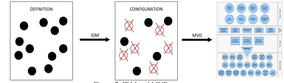
3.2.2. Model View Definition (MVD) 304
A Model View Definition (MVD) sets the interoperability at software level translating IDM 305
outputs in a readable language schema such as IFC (Asmi et al, 2015) as shown in Figure 7. 306
DEFINITION CONFIGURATION
IDM MVD
307
[image:11.612.70.528.575.710.2]11
The IDM outputs, such as BPMN process modelling, Exchange Requirements and Functional 309
Parts, will help developers to understand the interoperability required by the users between BIM 310
applications (Berard and Karlshoej, 2011; Belsky et al, 2014). With this data as a guideline, the 311
developer will set the interoperability from a technical point of view. Thus, each of the exchange 312
elements are translated into a readable language schemasuch as IFC. 313
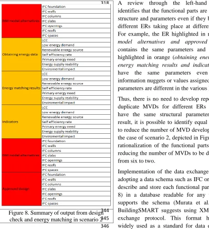
The first step to develop an MVD will be the rationalization of the functional parts to decrease 314
the number of MVDs to develop and to avoid duplicity. Figure 8 summarises the outputs or 315
functional parts developed for scenario 2 (Figure 5); the left-hand column groups the exchange 316
requirements (ER) while the details for each of them is shown in the right-hand column. 317
A review through the left-hand column 318
identifies that the functional parts are the same 319
structure and parameters even if they belong to 320
different ERs taking place at different times. 321
For example, the ER highlighted in red (BIM 322
model alternatives and approved design) 323
contains the same parameters and the ERs 324
highlighted in orange (obtaining energy data, 325
energy matching results and indicators) can 326
have the same parameters even if the 327
information nuggets or values assigned to these 328
parameters are different in the various ERs. 329
Thus, there is no need to develop repetitive or 330
duplicate MVDs for different ERs that can 331
have the same structural parameters. As a 332
result, it is possible to identify equal data and 333
to reduce the number of MVD development. In 334
the case of scenario 2, depicted in Figure 5, the 335
rationalization of the functional parts allowed 336
reducing the number of MVDs to be developed 337
from six to two. 338
Implementation of the data exchange requires 339
adopting a data schema such as IFC or XML to 340
describe and store each functional part (Figure 341
8) in a database readable for any tool that 342
supports the schema (Murata et al., 2005). 343
BuildingSMART suggests using XML as the 344
exchange protocol. This format has been 345
widely used as a standard for data exchange 346
[image:12.612.69.497.228.697.2]given its ability to manage small amount of data and to facilitate the exchange over the web 347
12
(Combi & Pozzi, 2005; Eastman et al., 2011). However, this schema is not adequate because it is 348
not able to describe the relationship between elements in the schema. Thus, the geometries dealt 349
by this schema are very simple (Abanda et al., 2013). Although BuildingSMART developed a 350
property called MVD-XML, they recognize the weakness of the format to include data from IFC 351
file (Paryudi, 2015; Pinherio et al, 2015). As a result, the format proposed by BuildingSMART 352
fails to translate the 3D geometry from BIM models. Because of this drawback regarding the 353
XML schema, this research will use the IFC schema for the interoperability. 354
3.3. Design cycle (Interoperability Specification Development in
355
Design4Energy) 356
The interoperability specification prescribed for the performance based building design, which 357
incorporates the BIM tools and technologies used by the stakeholders through engaging with the 358
data models. These are elaborated below. 359
3.3.1. Process modelling 360
The purpose of the process map is to describe the flow of activities in scenario 2, the roles played 361
by each actor involved and the information used or created by each of them. Figure 13 shows the 362
main components of the process model for the Concept Design Phase: Sketching a New Design 363
Within a Neighbourhood Context: Design Check & Energy Matching, which is the third 364
stage/phase in Figure 5 and part of scenario 2. The process models are produced for each stage of 365
the building lifecycle process in Figure 5. 366
The process model uses rows to categorize activities with different functional capabilities. The 367
rows identify the actors involved in the exchange while the columns show project phases. In the 368
cells of the rows, it is possible to represent activities as white rectangles and the data to be 369
exchanged is shown as corner folded blocks (Eastman et al., 2011). 370
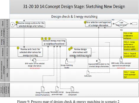
The process model illustrated in Figure 9 is one of the nine process models indicated in Figure 5 371
and focuses on matching the design alternatives with the district energy requirements. The 372
proposed workflow starts with the client reviewing the energy options for each alternative 373
produced in the previous Early Design Sketching phase. From these design options, the client 374
and architect will choose few options in a collaborative manner. 375
The selected options will be available for the energy expert, who will add energy data such as 376
energy price, energy potential maps and energy production components to match the design 377
proposed for the district. The results of this analysis will be passed to the architect via the 378
Design4Energy virtual collaborative workspace. These results will help to make some 379
corrections and improvements in the design alternatives. Finally, the design alternatives are 380
shared with the client, who will select an alternative through a comparative review of the 381
alternatives with indicators. 382
Yellow boxes in the process model in Figure 9 indicate what tools are used for which activity in 383
13
used in this process are coded as Tool 1: Target Assessment Tool, Tool 5: Energy Performance 385
Simulation Tool, Tool 6: Collaborative Workspace and Energy Match Optimizer Tool. 386
The process model helps in showing the functional requirements and describes how the 387
information exchange should work between the client, architect and the energy expert for the 388
energy matching theme at the neighbourhood level in the DesignCheck&EnergyMatching phase 389
of the building lifecycle process is shown and it reflects which exchange should take place 390
between which stakeholders conducting consecutive activities. The key activities in this process 391
are explained below. 392
[image:14.612.75.545.227.575.2]393
Figure 9: Process map of design check & energy matching in scenario 2 394
· Review energy options for the selected design alternatives: client receives the design 395
alternatives and energy performance simulation results from the energy expert to choose the 396
most suitable proposals for economic and aesthetic needs. 397
· Review and check the selected alternatives for energy matching: design alternatives 398
chosen previously will be checked by the architect and then these models will be analysed for 399
energy matching through the virtual collaborative workspace. 400
· Analyse energy matching at the district level: the energy expert runs a new analysis to 401
14
· Review design alternatives with energy matching results: the architect obtains the results 403
from the energy matching analysis and applies some changes to optimize the proposed 404
design. 405
· Final selection and approval of a design alternative: the client will analyse the BIM 406
models being developed to select the most appropriate option for economic, functional, 407
energy efficient and aesthetic needs. The selected alternative is shared via the virtual 408
collaborative workspace. 409
Main actors at this DesignCheck&EnergyMatching phase are the Client from Manchester, 410
Energy Expert from Helsinki and the Architect from Dresden. Following the scenario 411
development and process modelling studies in the project, there were clear understanding and 412
agreement between them for how they should interact and share information amongst them. This 413
then helped further granulation for the interoperability specification. Similar process modelling is 414
also carried out for the other stages of the cross-organisational processes shown in Figure 5. 415
3.3.2. Information Exchange Requirements 416
The next step is to specify the information exchange and its content with the Information 417
Exchange Requirements template that represent the link between process and data. It contains the 418
relevant data to ensure the correct exchange of data between two actors and their corresponding 419
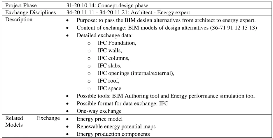
tasks in the integrated process (Berard and Karlshoej, 2011; Belsky et al, 2014). Table 1 shows 420
the BIM model exchange between architect and energy expert that is one of many exchanges in 421
Figure 9. 422
Project Phase 31-20 10 14: Concept design phase
Exchange Disciplines 34-20 11 11 - 34-20 11 21: Architect - Energy expert
Description · Purpose: to pass the BIM design alternatives from architect to energy expert.
· Content of exchange: BIM models of design alternatives (36-71 91 12 13 13)
· Detailed exchange data:
o IFC Foundation,
o IFC walls,
o IFC columns,
o IFC slabs,
o IFC openings (internal/external), o IFC roof,
o IFC space
· Possible tools: BIM Authoring tool and Energy performance simulation tool
· Possible format for data exchange: IFC
· One-way exchange
Related Exchange
Models
· Energy price model
· Renewable energy potential maps
[image:15.612.63.531.414.651.2]· Energy production components
Table 1: Information Exchange Template for sharing BIM models for design alternatives 423
The information exchange template encapsulates the information nugget to be exchanged 424
between the architect and the energy expert in this instance and the business process phase is 425
15
exchange requirement explained in the user requirements. In this instance, the aim of the 427
exchange is to pass the BIM models of design alternatives from the architect to the energy expert 428
(which should encapsulate building components such as IFC Foundation, IFC walls, IFC 429
columns, IFC slabs, IFC openings (internal/external), IFC roof and IFC space). This exchange 430
would take place from a BIM authoring tool used by the architect to the energy performance 431
simulation tool used by the energy expert. Finally, related exchange models are the preceding 432
and succeeding exchanges, which would set the expectation for the correct wrap of information 433
in the exchanges. 434
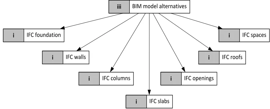
3.3.3. Functional parts 435
The functional part focuses on detailing the information encapsulated in an information model to 436
be exchanged. Each exchange requirement provides a series of functional part to be exchanged 437
as a result of an activity. Since that activity may be part of many exchange requirements, a 438
functional part can be bound to one or many exchange requirements. The granularity in this case 439
is defined by practical reasons, the BIM model alternatives (Figure 10) could be represented in a 440
very coarse functional part e.g. by floor or area, but in doing so will lead to develop MVDs that 441
contains a large amount of non-reusable data. On the other hand, a fine granularity will lead to 442
disintegrate the BIM model alternatives from its components e.g. IFC foundation, walls or 443
columns could be divided in even small data such as materials, cost, manpower and so on. 444
BIM model alternatives iii
IFC walls i
IFC columns i
IFC slabs i
IFC openings i
IFC roofs i
IFC foundation
i i IFC spaces
[image:16.612.82.525.379.559.2]445
Figure 10: Functional parts for the exchange requirement in table 1 446
Each exchange requirement in functional parts is considered sufficient such as constructive 447
elements (foundation, walls etc) and allowing to re-use the data in an MVD into another. 448
3.3.4. MVD examples 449
Having discussed the procedure to develop interoperability via IDM/MVD, this section will 450
introduce instances for Model View Definition in Design4Energy. Those instances are walls, U-451
16
The MVD schema shown in Figure 11 represents a generic wall for various parameter definitions 453
in the technical schema. 454
Walls Root Attributes
Generic Definition
Generic Association
Generic Object Placement
Shape Representation
Generic Voiding
Generic Containment GUID
BIM Object Owner
Name
Space Boundary
Property Definition Property Set
Generic Material Association
Material Layer Set
Pset_WallCommon Wall Construction Type
Wall Is Internal/External
Wall Composite Thermal Transmittance
Material Layer Material In Material Layer
EMP-ThermalAnalysis
Material Thermal Transmittance
Local Relative Placement
Generic Geometric Representation Bounding Box
Body
Mapped Item Representation
Building Element Voiding
Building Element In Spatial Container
2nd Level Space Boundary Space Boundary Geometry Planar Space Boundary
[image:17.612.64.545.104.566.2]455 456
Figure 11: MVD for generic IFC Wall 457
· The root attributes define a singular element using a Globally Unique Identifier (GUID), a 458
specific name and identifies the element creator. 459
· The generic definition is used to generate a property set for a generic wall. The properties 460
to be included are wall type, internal or external and thermal transmittance. 461
· The generic association is related to the material definition for the wall object that contains 462
a number of layers, e.g. a cavity wall with brick masonry and an air gap. 463
17
· The shape representation details the geometry used for a generic wall being able to set 465
three alternatives: bounding box or simplistic 3D representation; 3D body such as 466
wireframe, surface or solid; mapped item representation. 467
· The generic voiding defines the relationship between building elements and their openings. 468
· The generic containment connects walls with the spatial container where they are placed. 469
· The space boundary is a closed shell limited by planar walls; this space boundary describes 470
the materials contained in the boundary walls. 471
The U-Value is described in Figure 12 for the following entities: 472
Transfer of heat Units Material
MaterialConstitue nt
MaterialDefinition RelAssociatesMat
erial RelAssociates
Relationship
Root GUID Project name U Factor
Generic Definition Property
Definition Property Set Pset_WallCommon Units Transfer of heat Pset_SlabCommon Units
Transfer of heat
Pset_WindowCommon Units Transfer of heat
Pset_DoorCommon Units Transfer of heat
[image:18.612.41.543.66.653.2]473
Figure 12: MVD for IFC U-value 474
· The root attributes: define a singular element using a Globally Unique Identifier (GUID) 475
and a specific name. 476
· Relationships: allow for defining the thermal properties for a generic materialdescribing the 477
relationship between a material and an element. To do so, the following sub-entities are used: 478
18
material); RelAssociatesMaterial to define a relationship between materials and elements; 480
MaterialDefinition to define any material according to its layer, profile or constituents; 481
Material defines the units and transfer heat of the material to be used. 482
· The generic definition: is used to define the thermal properties in walls, slabs, windows and 483
doors. This entity set is defined by PropertyDefinition and PropertySet. They are useful to 484
generalize multiple properties contained in Pset_WallCommon, Pset_SlabCommon, 485
[image:19.612.58.544.100.480.2]Pset_WindowsCommon, Pset_WindowsCommon 486
Figure 13 illustrates the required entities to define a HVAC system: 487
488
Figure 13: MVD for IFC HVAC system 489
Port: defines a means to connect each element (sensors, equipment or components) in a HVAC 490
system. This Port is defined by RelConnectsPortToElement, DistributionElement and 491
FlowMovingDevice. RelConnectPortToElement is the relationship that defines the link 492
between the Port and DistributionElement. DistributionElement is a generalization of all 493
elements involved in the HVAC system. FlowMovingDevice defines the occurrence of a device 494
(compressor, pump or fan) used to distribute, circulate or perform the conveyance of fluids. 495
4.
Discussion
496There are seven process models covering the phases in Figure 5 for the integrated cross- 497
organisational business process workflow incorporating the three scenarios. In the research, 37 498
Exchange Requirements, 61 Functional Parts covering only scenario 1 and scenario 2 were 499
produced. In addition, 30 technical schemas with MVD models including life cycle cost, usage 500
indicators, a self-efficiency rate, site potentials and features, U-value, walls, columns, slabs, 501
19
HVAC systems, HVAC equipment, for cooling, photovoltaic panels were produced in the 503
research, which are comprising of the interoperability specification for the Design4Energy 504
system. In this paper, it was only possible to represent one from each IDM and three MVD 505
examples. 506
The interoperability specification helped to develop the virtual collaborative workspace, in which 507
how information exchange between whom at what stage in the process using which data model 508
encapsulating what information nuggets are defined and eventually the specification is used 509
through the demonstration of the virtual collaborative workspace that interacts a number of BIM 510
tools. Without the development of the specification in the Design4Energy project, it was not 511
possible to build the coherent picture of the whole building lifecycle or understanding amongst 512
the stakeholders about how the integrated BIM practice would be possible for performance based 513
design and retrofit including the neighbourhood parameters. For example, the process model 514
diagram illustrated in Figure 9 represents the main functional parts of the process stage: design 515
check and energy matching within a district context. The main set of tools required is: D4E 516
Collaborative Workspace Tool (Design Review Tool), Energy Match & Optimiser Tool, Energy 517
Performance & Simulation Tool and Target Setting & Assessment Tool, as shown in Figure 14. 518
[image:20.612.114.497.339.413.2]519
Figure 14: Tools interacting in the design check & energy matching 520
In this interaction in Figure 14, interoperability specification helped the technical teams in the 521
project to understand and configure their tools for what data specifically should be filtered from 522
a BIM tool to the other. Figure 15 shows the outcomes of the interactions from figure 14, 523
representing the case study example of design check and energy matching demonstration and its 524
outcomes using the D4E Collaborative Workspace that executed the interoperability 525
specification between the tools in Figure 15 by the architects, client and the energy experts in 526
Design4Energy. 527
The workflow process of the information exchange and activities related to the design 528
alternatives with various energy options can be viewed and shared by the stakeholders for the 529
performance based design in developing prosumer buildings. It should also be noted that 530
BuildingSmart initiated IDM and MVD techniques as originally issued are mainly data and 531
technology oriented and have less emphasis on human and process aspects and complicated with 532
the technical jargons that confused both user partners and the technical partners. That is why, in 533
Design4Energy, interoperability specification development started with the scenario 534
developments that are then translated into the specific process models, which are heavily 535
discussed and agreed by both technical and user partners. Following that, the process models are 536
20
which are used by the technical team to develop their tools for successful communication and 538
interactions with other tools in the whole Design4Energy system. Therefore, it is recommended 539
that further issues of the IDM and MVD techniques by BuildingSmart should also consider the 540
user-friendliness, flexibility aspects. In other words, human and process dimensions of the 541
interoperability for the wider use and straightforward implementation of them in the 542
interoperability specification development, which may vary from projects to projects since each 543
project has its own goal, scope, priorities and features 544
That means that there is no one-fit-for-all solution for interoperability despite the available 545
standards. In this paper, the detailed examples from the interoperability specification are given 546
and the paper prescribes how it is practically developed using with the IDM and MVD protocols 547
by addressing project specific scope and priorities. Thus, the paper demonstrates an approach for 548
how interoperability specifications can be practically and systematically developed for integrated 549
BIM use by considering human, process, technology, data models and information dimensions 550
together. 551
The interoperability specification framework, shown in Figure 16, in this research brings 552
together the three scenarios (district, holistic building design and retrofit), reflecting the 553
Design4Energy project scope and it prescribes how each of these scenarios can be integrated into 554
a coherent process workflow, where stakeholder definitions, tools and technologies for data 555
manipulation and processing, information exchange requirements models and technical schemas 556
are specified at the various stages of the integrated process workflow for the performance based 557
design, not only for a passive design but also for an energy producing building design through a 558
BIM-enabled collaborative virtual workspace. The interoperability framework shown in Figure 559
[image:21.612.66.536.193.389.2]16 is the rationalised version of the interoperability vision given in Figure 2. 560
21
22
In Figure 16, the higher-level building life cycle stages are defined based on the international 551
Omniclass classification and for each stage, an integrated process model is developed for the 552
corresponding scenarios (scenario 1: district; scenario 2: holistic design; and scenario 3: retrofit). 553
For stage three (Concept Design Stage: Energy matching), the process model is shown in this 554
paper in Figure 9. Tools are mapped into the framework in accordance with their use in the 555
process while the information exchange and data structuring is laid out within the system 556
architecture perspective including the User Interface Layer, the Service Layer and the Data Layer 557
of the Collaborative Workspace of the Design4Energy project. This indicates that the integration 558
of design knowledge base and interoperation of building modelling for effective lifecycle 559
information management for performance based design is critical and only possible via the 560
Integrated BIM practice. 561
The interoperability specification in Figure 16 represents a novel approach and contributes to 562
knowledge in literature and practice to understand the key aspects to consider for the 563
interoperability requirements and proposes a practical approach for the interoperability 564
developments for the Integrated BIM use for the prosumer building projects. 565
The interoperability specification development also reflects a forward-thinking approach to 566
address the interoperability challenges in a practical way for the BIM implementation at Level 2 567
and Level 3, which is already promoted by the UK Government’s policy agenda in leading the 568
UK construction industry towards sustainable design and FM through the Integrated BIM 569
practice. Finally, the proposed interoperability specification development approach also provides 570
the theoretical basis for the effective development of BIM execution plans in practice for energy 571
efficient prosumer building design and construction. 572
5.
Conclusion
573The performance based design requires a holistic design approach that entails multiple 574
stakeholders interacting with a lifecycle perspective and requires considering neighbourhood 575
level aspects and the use of various BIM applications. This leads to a significant need for the 576
integration of multi-domain performance simulation and analysis. Furthermore, traditionally, 577
architects and engineers find it difficult to effectively use performance simulation tools because 578
their processes are based on 2D manually-created drawings. This characteristic is necessitated by 579
the lack of understanding of interoperation and the lack of integration between design models 580
and building energy models. To overcome this challenge, in the Design4Energy Project, an 581
interoperability specification is developed for the effective and efficient data and process 582
integration, which is also executed by the Design4Energy collaborative workspace system for the 583
Integrated BIM use. 584
This paper explained the development of an interoperability specification for the Integrated BIM-585
practice for the Design4Energy system that executes the interoperability specification for 586
23
design. It provides a solid foundation for developing a holistic and coherent picture of cross-588
organisational business processes, which reflects an integrated supply chain for energy 589
efficiency, not only for a passive design but also for an energy producing building design 590
through a BIM-enabled collaborative virtual workspace. 591
The cross-organisational business process modelling and the interoperability specification 592
development have adopted IDM recommended by BuildingSMART, which was, however, 593
focusing on more data and technologies than people and processes. Therefore, it was difficult to 594
adopt it initially in the Design4Energy project without addressing the people and process aspects. 595
The research work described here is the very first of its kind utilising the integrated process 596
modelling using IDM for energy efficient design development by bringing energy databases, 597
simulation and collective knowledge exploration through an integrated supply chain. The main 598
achievements of the research in this paper are listed below: 599
1. Interoperability specification pulls together three scenarios to bring the district context and 600
energy trading into a holistic energy efficient building design for new and existing 601
buildings. 602
2. A complete integrated process workflow for new building design is developed and 603
implemented based on scenario 1 and scenario 2, Information Exchange requirements and 604
functional parts of the information exchange models. Thus, it is now possible to state what 605
tools by whom would manipulate which data model by processing what information at 606
which phase of the integrated design process from a very high level to a very detailed level. 607
3. It coherently pulls together all the research and development from all the users and technical 608
partners in the Design4Energy project. 609
4. The ongoing iterative cycle of development, namely the interoperability specification 610
development within scenario 2 is approved by the end users from Spain, UK, Finland and 611
Germany and it is extended towards scenario 3. The interoperability specification formed a 612
pivotal position in the Design4Energy project for the performance based design 613
development. 614
5. IDM and MVD methods are difficult to use without addressing the human and process 615
dimensions that the paper addresses the user-friendliness and usability of IDM and MVD 616
methods and discusses in-depth about the interoperability issues of the Architecture, 617
Engineering and Construction (AEC) area from a performance based design perspective 618
addressing the human and process aspects in addition to the technology and data aspects for 619
the Integrated BIM practice. 620
6. The interoperability specification development approach in the paper can help for the 621
development of successful and practical BIM Execution plans for the Integrated BIM 622
24 REFERENCES
624
Abanda, F., Zhou, W., Tah, J. and Cheung, F. (2013), Exploring the relationships between linked 625
open data and building information modelling, Proceedings of the Sustainable Building,
626
Conference Coventry University, Coventry, pages 176-185, ISBN 978-1-84600-049-2 627
Aouad, G. and Arayici, Y. (2010), “Requirements Engineering for Computer Integrated 628
Environments in Construction”. Chichester: Wiley-Blackwell, Inc. ISBN: 9781405189453
629
Arayici, Y., (2015), “Building Information Modelling”, Bookboon publisher, ISBN: 978-87-403-630
1098-6, http://bookboon.com/en/building-information-modeling-ebook 631
Asmi, E., Robert, S., Haas, B., Zreik, B., (2015), “A standardized approach to BIM and energy 632
simulation connection”, International Journal of Design Sciences and Technology, 21:1, 59-82 633
ISSN 1630-7267 634
Paryudi, I., (2015), “Architects and Energy Simulations Tool”, International Journal of Scientific 635
& Technology Research, Vol 4, Issue 3, ISSN 2277-8616 636
Azhar, S., Carlton, W. A., Olsen, D., & Ahmad I. (2011), “Building Information Modelling for 637
sustainable design and LEED® rating analysis”, Automation in Construction, 20(2), pp. 217-638
224, http://dx.doi.org/10.1016/j.autcon.2010.09.019 639
Bahar, Y., Pere, C., Landrieu, J. and Nicolle, C. (2013), A Thermal Simulation Tool for Building 640
and Its Interoperability through the Building Information Modelling (BIM) Platform, 641
Buildings3(2), 380-398. doi:10.3390/buildings3020380 642
Belsky, M., Eastman, C., Sacks, R., Venugopal, M., Aram, S., and Yang, D., (2014), 643
“Interoperability for precast concrete building models”, PCI Journal 59(2):144-155, DOI: 644
10.15554/pcij.03012014.144.155 645
Berard, O., Karlshoej, J., (2011), “Information Delivery Manuals to Integrate Building Product 646
Information into Design”, Proceedings of the CIB W78-W102 2011: International Conference – 647
Sophia Antipolis, France, 26–28 October, ISBN 978-92-79-20811-9 648
Combi, C. and Pozzi, G (2005), “Building XML documents and schemas to support object data 649
exchange and communication,” Database and expert systems applications, 16th international
650
conference, DEXA Copenhagen, Denmark, pp 353-364, ISBN 978-3-540-31729-6
651
Deutsch, R. (2011). BIM and integrated design: Strategies for architectural practice. New
652
Jersey: John Wiley & Sons, Inc, ISBN: 978-0-470-57251-1
653
Eastman, C.M., Jeong, Y.-S., Sacks, R., and Kaner, I. (2010), "Exchange Model and Exchange 654
Object Concepts for Implementation of National BIM Standards" Journal of Computing in Civil 655
Engineering, Volume 24, Issue 1 p. 25-34., doi.org/10.1061/(ASCE)0887-3801(2010)24:1(25) 656
Eastman, C., Teicholz, P., Sacks, R., Liston, K. (2011), BIM Handbook: A Guide to Building 657
Information Modelling for Owners, Managers, Designers, Engineers and Contractors, John 658
Wiley & Sons, Inc, New Jersey, ISBN: 978-0-470-54137-1 659
Ellis, T. J. and Levy, Y. (2009), “Towards a guide for novice researchers on research 660
methodology: Review and proposed methods”, Issues in Informing Science and Information 661
Technology, Volume 6, 323-337, ISSN: 1547-5867, http://iisit.org/Vol6/IISITv6p323-662
25
Elvin, G. (2007), “Integrated practice in architecture, Mastering Design-Build, Fast-Track, and 664
Building Information Modelling”, New Jersey: John Wiley & Sons, ISBN: 978-0-471-99849-5 665
Hemsath, T. (2015), “Energy Modelling in Conceptual Design”, in Building Information 666
Modelling: BIM in current practice (edited by Karen M. Kensek & Douglas Noble), John Wiley 667
& Sons, Inc., New Jersey, 7 (26) 95-108, DOI: 10.1002/9781119174752.ch7 668
Hetherington, R., Laney, R., & Peake, S. (2010), “Zero and low carbon buildings: A driver for 669
change in working practices and the use of computer modelling and visualization”, In: 14th 670
International Conference on Information Visualisation, 27-29 July 2010, London South Bank 671
University, London, UK, DOI:10.1109/IV.2010.86
672
Hevner, A., Chatterjee, S., (2010), “Design Research in Information Systems”, Integrated Series 673
in Information Systems Vol 22, DOI 10.1007/978-1-4419-5653-8_2 674
ISO (2016), ISO 29481-1:2016 Building Information Models, Information Delivery Manual, 675
Part 1: Methodology and Format”, International Organisation for Standardisation, ISO 29481-676
1:2016 677
Juan, D. and Zheng, Q. (2014), “Cloud and Open BIM-Based Building Information 678
Interoperability Research”, Journal of Service Science and Management, Vol 7, 47-56, 679
DOI:10.4236/jssm.2014.72005, 680
Jeong, W., Kim, K., (2016), “A Performance Evaluation of the BIM-Based Object-Oriented 681
Physical Modelling Technique for Building Thermal Simulations: A Comparative Case Study”, 682
Sustainability, 8, 648; doi:10.3390/su8070648,www.mdpi.com/journal/sustainability 683
Krygiel, E. and Nies, B. (2008), “Green BIM: Successful sustainable design with building 684
information modelling”, Indianapolis, Wiley Publishing, Inc, ISBN: 978-0-470-23960-5 685
Kymmell, W. (2008), “Building Information Modelling: Planning and managing construction 686
projects with 4D and simulations, (McGraw-Hill Construction Series), The McGraw-Hill 687
Companies, Inc. ISBN: 9780071494533 688
Laakso, M & Kiviniemi, A (2012), “The IFC standard - a review of history, development, and 689
standardization”, Journal of Information Technology in Construction, Vol 17, pp. 134-161, 690
ISSN: 1874-4753 691
Levy, F. (2012), “BIM: in Small-scale Sustainable Design”, John Wiley & Sons, Inc, New 692
Jersey, ISBN: 978-0-470-59089-8 693
Motawa, I., Carter, K., (2013), “Sustainable BIM based Evaluation of Buildings”, Procedia - 694
Social and Behavioural Sciences, Vol 74 (29), pp 419-428, doi.org/10.1016/j.sbspro.2013.03.015 695
Muhic, S., Krammer, M., (2015), “Utilising IFC for indoor positioning”, in eWork and 696
eBusiness in Architecture, Engineering and Construction by Martens, Mahdavi & Scherer (Eds), 697
Taylor and Francis Group, London, ISBN 978 1 138 02 710 7 698
Murata, M., Lee, D., Mani, M. and Kawaguchi, K. (2005), Taxonomy of XML Schema 699
Languages using Formal Language Theory, ACM Transactions on Internet Technology, 5(4), pp
700
660–704, DOI:10.1145/1111627.1111631
701
Ouyang, C., Dumas, M., Van Der Aalst, WMP., Ter Hofstede, AHM., Mendling, J., (2009),
702
“From Business Process Models to Process-Oriented Software Systems” ACM Transactions on
703