NEURAL NETWORK SPEED CONTROLLER
FOR DIRECT VECTOR CONTROL
OF INDUCTION MOTORS
BEN HAMED MOUNA
National Engineering School of Gabes (ENIG), Tunisia, University of Gabes, [email protected]
SBITA LASSAAD
National Engineering School of Gabes (ENIG), Tunisia, University of Gabes [email protected]
Abstract:
This paper presents a new method for the implementation of a direct rotor flux control (DRFOC) of induction motor (IM) drives. It is based on the rotor flux components regulation. In fact, the d and q axis flux components feed a proportional integral (PI) controller. The outputs of which are the targets start voltages (vdsref and vqsref). While, the synchronous speed is depicted at the output of rotor speed controller. In order to accomplish variable speed operation, conventional PI lie controller is commonly used. This controller provides limited good performances over a wide range of operation even under ideal field oriented conditions. An alternate approach is to use the so called neural network controller. The overall investigated system is implemented using dSpace system based on digital signal processor (DSP). Simulation and experimental results have been presented for one kw IM drives to confirm the validity of the proposed algorithms.
Keywords: DRFOC; neural network; variable speed drives; control; IM; real time.
1. Introduction
DFOC is based on the regulation of the IM flux. Different strategies are proposed in the literature [Rao (2009), Gadoue (2009), Ben Hamed (2008), Ba Razzouk (1997), Comanescu (2009), Trentin (2009), Verselic (2008) and Santana (2008)]. They are based on the speed and flux magnitude regulation with or without the decoupling compensators. The slip angular frequency to align the IM flux with the d axis is computed using the Park IM model making the proposed DFOC scheme sensitive to IM parameters.
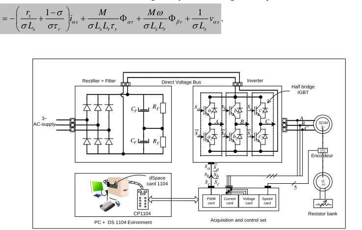
In this paper, we propose a new method to achieve the direct rotor field oriented control (DRFOC). The needed rotor flux components are reconstructed using the IM model. A neural network controller is used in speed control loop. The overall investigated system (Fig. 1) is implemented using dSpace system based on digital signal processor (DSP). Simulation and experimental results have been presented for one kw IM drives to confirm the effectiveness of the proposed system.
2. Induction motor model
Assuming linear magnetic circuits, equal inductances and neglecting iron losses, the mathematical model of the IM viewed from the stator reference frame is given by the following set of equations:
1 1
s s
s r r s
s r s r r s r s
di r M M
i v
dt L L L L L L
. (1)
1 1
s s
s r r s
s r s r s r r s
di r M M
i v
dt L L L L L L
. (2)
s
s s s d
v r i dt
. (3)
s
s s s
d
v r i
dt
. (4) 1
r
s r r
r r d M i dt
. (5) 1
r
s r r
r r d M i dt
. (6)
WhereLsand Lr are the stator and rotor self inductances respectively, Mis the mutual inductance, rs is the stator resistance, r is the rotor time constant, is the motor leakage coefficient, is the rotor electrical angular velocity, is, is, is and vsare the stator currents and voltages components, s, s, r and
r
are the stator and rotor fluxes components respectively.
The electromagnetic torque equation and the electrical angular speed are related by G F R F R F C Current card Voltage card Speed card PWM card
Acquisition and control set
SCIM 3~ ---- --- ----CP1104 dSpace card 1104 3~ AC-supply
Direct Voltage Bus
1 a 2 a 1 b 2
b c2
1 c
A B C
a s a s b s b s c s c s a s b s c
s sc b sa s F C --Half bridge IGBT 5 C A B
PC + DS 1104 Evironment
Inverter Rectifier + Filter
Enco deur
Resistor bank
e L
dJ P T T f
dt
. (7) In (7), J is the moment of inertia of the IM, f is the friction constant, Te and TLare the electromagnetic and load torques respectively and P is the number of pair poles.
3. Proposed DRFOC scheme for IM drives
Based on the dynamic IM model represented according to the usual d and q axis components in a synchronous rotating frame, the d and q rotor flux components can be written as:
s
dr ds d
r s r s r s
M r
v E
1 L L s s²
. (8)
s
qr qs q
r s r s r s
M r
v E
1 L L s s²
. (9)
and its synchronous speed is given as
s sl
. (10) The coupling terms Ed and Eq are expressed with the following expressions
s r r r s r s r s qr r s r s dr
r s r s
d
r s r s r s
M² M²
2 s
r r r
E
1 L L s s²
s s
r r s s s s r dr r s r s qr
r r s r s
q
r s r s r s
1 s
r r r r r
E
1 L L s s²
.
Here, r and s are the slip speed and the stator time constant.
It can be seen from (1) that it is possible to control the d and q fluxes separately if the coupling terms Ed and q
E are equaled to zero on one hand. On the other hand, it is shown from (2) that the rotor speed is controlled with the synchronous speed if the slip speed, imposed with the load torque, is equaled to zero. Therefore, a d, q stator flux components and speed controllers are to be used to attenuate the effect of the decoupling disturbances and load torque appliance.
The new decoupling method needs the rotor flux components. As it is well known that the rotor flux is unmeasured. Therefore, in this paper, it is reconstructed based on the dynamic IM model.
4. Speed and rotor flux components controllers design
4.1. Neural network speed controller
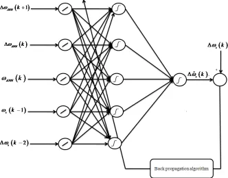
The following section describes the design procedure for the neural network speed controller (NNC). The objective of this NNC is to develop a back propagation algorithm such that the output of the neural network speed observer can track the target one. Fig. 2 depicts the network structure of the NNC, which indicates that the neural network has three layered network structure. The first is formed with five neurons inputs (ANN
k1
,
ANN k
,ANN
k , s
k1
ands
k2
. The second layer consists of five neurons. The lasted onecontains one neuron to give the command variations
k . The aim of the proposed NNC is to compute thecommand variation based on the future output variationANN
k1
. Hence, with this structure, we realize a predictive control with integrator. At time k, the neural network computes the command variation based on the output at time (k+1), while the later isn’t defined at this time. In this case, we suppose that
1
ANN k ANN k
1
s k s k G s k
. (11)
The proposed NNC was trained with the procedure illustrated in Fig. 3. 4.2. PI rotor flux components controllers
It can be seen that the d axis and q axis voltage equations are coupled by the terms
E
d andE
q. These terms are considered ads disturbances and are cancelled by using the proposed decoupling method. If the decouplingmethod is implemented, the flux components equations become
Fig. 2. Neural network speed controller.
dr G(s)vds
. (12) qr G(s)vqs
. (13) Thus, the dynamics of the d axis and q axis are now represented by simple linear second order differential equations. Therefore, it is possible to effectively control the flux components with a PI controller.
If we assume that the
E
d andE
qare cancelled by the proposed decoupling method, the transfer function of the d axis flux component is expressed as
dr s
ds r s r s r s
M r G(s)
v 1 L L s s²
. (14)
The numerical application leads to
58.8
( )
1.8 227.8 G s
s s
. (15)
The open loop flux transfer function with the PI controller is then expressed as
58.8
( ) 1.8 227.8 p i BO p k k
G s s
s k s s
. (16)
The pole dominant pole compensation method leads to
58.8
( ) ² 227.8 p BO k F s s s
. (17)
Then, the closed loop transfer function is reduced to 58.8
( )
² 227.8 58.8
p dr TBF drref p k F s
s s k
. (18)
admitting the following characteristic equation ² 227.8 58.8 p 0
s s k . (19) The last one is to be identified to a desired characteristic equation defined as
² 2 d nd ²nd 0
s s . (20) Finally, the PI controller parameters are defined as
1.8
i p
k k . (21) ²
58.8
nd p
k . (22) Where nd and d denote the natural frequency and damping ratio respectively kp and kiare the proportional
and integral gains of the PI controller.
As the dynamics of the d and q axis rotor flux components are equivalent, the PI gains can be copied to the q axis controller.
5. Simulation and experimental results
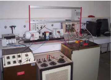
The laboratory prototype used to verify the behavior of the proposed DRFOC with the neural network speed estimator and controller is shown in Fig. 4. It consists of dSpace system with DS1104 controller board based on digital signal processor (DSP) TMS320F240 with its connector panel, control PC and a DC machine mechanically coupled to IM. The switched load resistor box is used to change the loading of the IM. A three phase Insulated Gate Bipolar Transistor (IGBT) inverter is used as power stage with a full controlled rectifier. The IM stator currents and voltages are measured by LEM sensors and processed by 16-b A/D converters. An incremental encoder position sensor delivering 1024 pulses per revolution is mounted on the rotor shaft of the IM only for comparison of the estimated and actual IM speeds. The pulse width modulation to control the power modules are generated by dSpace system.
suitable virtual instrument has also been developed to manage an on line all required electrical and mechanical signals of the IM.
Experiments were carried out on various operating conditions to highlight the performance of the proposed algorithms.
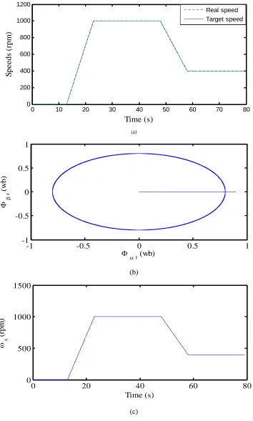
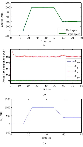
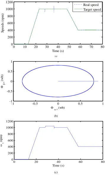
Some selected simulation and experimental results are presented here. In Figs 5 and 6, actual, synchronous speed and rotor flux trajectory are presented for variable target rotor speed at no load torque. Here, the neural network speed coming from the microcontroller is also reported and it can be noted how it accurately the measured signal both in simulation and in experimentation, especially at steady state on one hand. On other hand, it can be seen from these results that the decoupling of IM motor is established as the rotor flux follows a circular trajectory both in simulation and in experimentation.
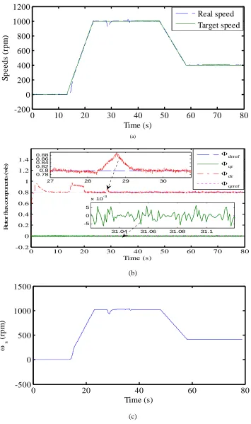
Investigating the ability of the drive to reject load disturbances, the drive is initially operated at 1000rpm. A sudden step increase of 50% rated load torque is applied at 28s and then removed at 36s. the obtained response are shown in Figs.7 and 8 as it is given in Figs 7(a) and 8(a) , the neural network estimated and controlled speed coincide with the actual and target speeds respectively despite of external disturbances. In addition, the rotor flux trajectory follows a circular one expected at loading and unloading conditions where a tiny error appeared and thanks to the used controllers, this error despaired, proving the robustness of the neural network speed estimator and controller and decoupling method against external disturbances. Note that during implementation, the loading of the motor was accomplished though the DC generator using the load box switches. Consequently, the simulated loading behaviors of the drive are slightly different than the implemented one.
(a)
(b)
(c)
Fig. 5. Simulation results for variable target speed under no load appliance: (a) real and target speeds, (b) rotor flux trajectory and (c) synchronous speed.
0 10 20 30 40 50 60 70 80
0 200 400 600 800 1000 1200
Time (s)
S
p
e
e
ds (rpm
)
Real speed Target speed
-1
-0.5
0
0.5
1
-1
-0.5
0
0.5
1
r
(wb)
r
(w
b)
0
20
40
60
80
0
500
1000
1500
Time (s)
s(r
pm
(a)
(b)
(c)
Fig. 6.Experimental results for variable target speed under no load appliance: (a) real and target speeds, (b) rotor flux trajectory and
0
10
20
30
40
50
60
70
80
-200
0
200
400
600
800
1000
1200
Time (s)
S
p
eed
s (rpm
)
Real speed
Target speed
0
10
20
30
40
50
60
70
80
0
0.2
0.4
0.6
0.8
1
Time (s)
R
o
to
r f
lux com
p
onent
s (
w
b)
drref
qr
dr
qrref0
20
40
60
80
-500
0
500
1000
1500
Time (s)
s(rpm
(a)
(b)
(c)
Fig. 7. Simulation results for variable target speed under load appliance: (a) real and target speeds, (b) rotor flux trajectory and (c) synchronous speed.
0
10
20
30
40
50
60
70
80
0
200
400
600
800
1000
1200
Time (s)
S
p
eeds (
rpm
)
Real speed
Target speed
-1
-0.5
0
0.5
1
-1
-0.5
0
0.5
1
r
(w
b)
r(wb)
0 20 40 60 80
0 200 400 600 800 1000 1200
Time (s)
s
(rp
m
(a)
(b)
(c)
Fig. 8. Experimental results for variable target speed under load appliance: (a) real and target speeds, (b) rotor flux trajectory and (c) synchronous speed.
0
10
20
30
40
50
60
70
80
-200
0
200
400
600
800
1000
1200
Time (s)
S
p
eeds (
rpm
)
Real speed
Target speed
0 10 20 30 40 50 60 70 80
-0.2 0 0.2 0.4 0.6 0.8 1 1.2 1.4
R
o
tor
f
lux c
om
pone
n
ts
(
w
b)
Time (s)
31.04 31.06 31.08 31.1 -5
0 5
x 10-3
27 28 29 30
0.78 0.8 0.82 0.84 0.86
0.88 drref
qr dr
qrref
0
20
40
60
80
-500
0
500
1000
1500
Time (s)
s(rpm
6. Conclusions
This paper has described the design, simulation and test of a simple but effective fuzzy logic controller for DRFOC of IM drives. Through a series of simulations and experimental results, the speed tracking and disturbance rejection capabilities of the controller were verified. Besides, the proposed DRFOC scheme shows good dynamic performances.
All high performances of DRFOC IM drives require accurate rotor flux components. In this paper, they are reconstructed using the IM model. The later is IM parameters depended. However, these parameters are altered especially with temperature. To improve the performance of the overall drive system, a robust rotor flux estimation algorithm is to be investigated. This will be the subject of future follow up work.
References
[1] Blaschke F. (1972): The principle of field orientation applied to the transvector closed loop control system for rotating field machines, Siemens Review, 34, pp. 217–220.
[2] Boglietti A. et al. (2008): Determination of critical parameters in electrical machine thermal models, IEEE Transactions on Industry Applications, 44, pp. 1150–1159.
[3] Ba Razzouk A. et al. (1997): Field oriented control of induction motors using neural networks decouplers, IEEE Transactions on Industry Power Electronics, 12, pp. 752–763.
[4] Ben Hamed. M et al. (2008): Neural Networks for controlled Speed Sensorless Direct Field Oriented Induction Motor Drives, International Journal of Electrical Engineering (JEE), 8, 84–90.
[5] Comanescu M. (2009): An Induction-motor speed estimator based on integral sliding-mode current control, IEEE Transactions on Industry Electronics, 56, pp. 3414–3423.
[6] Dong X. et al. (2009): Fuzzy-logic-based V/f control of an induction motor for a DC grid power-leveling system using flywheel energy storage equipment, IEEE Transactions on Industry. Electronics, 56, pp. 3161–3168.
[7] Gadoue S. M. et al. (2009): MRAS sensorless vector control of an induction motor using new sliding-mode and fuzzy-logic adaptation, IEEE Transactions on Energy Conversion, 99, pp. 1–9.
[8] Gao Z. et al. (2008): A sensorless adaptive stator winding temperature estimator for mains fed induction machines with continuous operation periodic duty cycles, IEEE Transactions on Industry Applications, 44, pp. 1533–1534.
[9] Gadoue S. M. et al. (2009): Sensorless control of induction motor drives at very low and zero speeds using neural network flux observers, IEEE Transactions on Industry Electronics, 56, pp. 3029–3039.
[10] Hasan S. and Husain I. (2009): A Luenberger–sliding mode observer for online parameter estimation and adaptation in high-performance induction motor drives, IEEE Transactions on Industry Applications, 45, pp. 772–781.
[11] Khalil H. K. et al. (2009): Speed observer and reduced nonlinear model for sensorless control of induction motors, IEEE Transactions on Control. System Technology, 17, pp. 327–339.
[12] Lascu C. et al. (2009): Class of speed-sensorless sliding-mode observers for high-performance induction motor drives, IEEE Transactions on Industry Electronics, 56, pp. 3394–3403.
[13] Missiala M. et al. (2008): Fuzzy self-tuning speed control of an indirect field-oriented control induction motor drive, IEEE Transactions on Industry Applications, 44, pp. 1732–1740.
[14] Maiti S. et al. (2008): Model reference adaptive controller based rotor resistance and speed estimation techniques for vector induction motor drive utilizing reactive power, IEEE Transactions on Industry Electronics, 55, pp. 594–601.
[15] Rubaai A. et al. (2008): DSP based laboratory implementation of hybrid fuzzy PID controller using genetic optimization for high performance motor drives, IEEE Transactions on Industry Applications, 44, pp. 1977–1986.
[16] Rae K. and Kiseok J. (2009): Induction motor rotor temperature estimation based on a high-frequency model of a rotor bar, IEEE Transactions on Industry Applications, 45, pp. 1267–1275.
[17] Rao S. et al. (2009): Simultaneous state and parameter estimation in induction motors using first and second order sliding modes, IEEE Transactions on Industry Electronics, 57, pp. 3369–3376.
[18] Sbita L. (2008): Contribution in digital control of systems: Application to digital control of sensorless induction motor drive, dissertation of HDR, National Engineering School of Sfax, Tunisia.
[19] Slvatore N.et al. (2009): Optimization of delayed state kalman filter based algorithm via differential evolution for sensorless control of induction motors, IEEE Transactions on Industry. Electronics, 57, pp. 385–394.
[20] Santana E. S. et al. (2008): A predictive algorithm for controlling speed and rotor flux of induction motor, IEEE Transactions on Industry Electronics, 55, pp. 4398–4407.
[21] Szabut K. et al. (2009): Indirect adaptive control of induction motor drive system with an elastic coupling, IEEE Transactions on Industry Electronics, 56, pp. 4035–4042.
[22] Trentin A. et al. (2009): Optimized commissioning method for enhanced vector control of high-power induction motor drives, IEEE Transactions on Industry Electronics, 56, pp. 1708–1717.
[23] Verselic B. et al. (2008): High performance position control of induction motor using discrete time sliding mode control, IEEE Transactions. Industry. Electronics, 55, pp. 3809–3817.