NOVATEUR PUBLICATIONS International Journal of Research Publications in Engineering and Technology [IJRPET] ISSN: 2454-7875 VOLUME 3, ISSUE 7, July-2017
101 |
P a g e
IMPLEMENTATION OF GRID INTERCONNECTION OF RENEWABLE ENERGY
SOURCES AT DISTRIBUTION LEVEL WITH POWER QUALITY IMPROVEMENT
FEATURES
HRISHIKANT P.BALWATKAR
Department of Electrical Engineering, Bhivarabai Sawant College of Engineering and Research, Narhe, Pune-411041
PROF. A. P. KINGE
Department of Electrical Engineering, Bhivarabai Sawant College of Engineering and Research, Narhe, Pune-411041
ABSTRACT:
The non-renewable energy sources are continuously used over the last several decades and the need of the time is to reduce their use. The researchers are working to study the feasibility of other sustainable sources of the energy. The challenge of the energy crisis has to be addressed and the researchers were contributing in this regards continuous. The requirement of the present time is to develop the non renewable energy systems in coordination with the grid. The grid interconnected non conventional sources have been facing the problems with the quality of power and feasibility. Authors have implemented the power quality improvement model for the grid connected system in order to enhance its performance.
KEY WORDS: PV Solar System, Wind Systems, Shunt active filter, Series active filter etc.
I. INTRODUCTION:
The unbalanced load creates the various affects on the performance of the power system [1]. The problems associated with the distributions systems mainly are in terms of introduction of harmonics in the supply. The use of the active filters may help in improvements in the performance [2]. The objective of this work is to design a
control circuit for the existing inverter which can function as a conventional inverter and as Shunt Active Power Filter [3]. The approaches like conditioning of the load and line are found useful for improvement of voltage quality. Harmonic currents were mitigated by shunt filters [4]. Authors have proposed the implementation of the active filters with power electronics and microcomputer control with the approach to reduce the cost of the system. Active filters are becoming more popular than the passive filters due to wide range of the power electronics circuits to be used in combination. A special attention was given to the active filter because of their functions and Advantages:
High speed response.
Flexibility in defining and implementing the filter functions.
Elimination of the resonance problems of the compensation equipment.
II. IMPLEMENTED MODEL:
Authors have implemented the system as shown in figure below. The system implemented is three phase four wire. The grid connected wind system is proposed and the performance improvement of the system was achieved. The control is achieved with the connected capacitor.
VOLUME 3, ISSUE 7, July-2017
102 |
P a g e
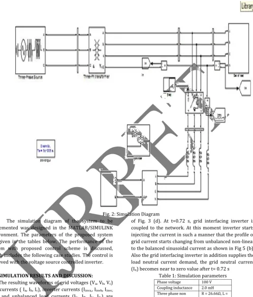
Fig. 2: Simulation Diagram The simulation diagram of the system to be
implemented was designed in the MATLAB/SIMULINK environment. The parameters of the proposed system are given in the tables below. The performance of the system with proposed control scheme is discussed, which includes the following case studies. The control is achieved with the voltage source controlled inverter.
III. SIMULATION RESULTS AND DISCUSSION:
The resulting waveforms of grid voltages (Va, Vb, Vc) grid currents ( Ia, Ib, Ic), inverter currents (Iinva,, Iinvb, Iinvc, iinvn) and unbalanced load currents (Ila, Ilb, Ilc, Iln) are shown in Fig. 3 And Fig. 4 shows the same waveforms as in Fig. 3 for time interval 0.81 to 1. Also Fig. 5 shows corresponding active-reactive powers of grid (PGrid, QGrid), load (PLoad,QLoad) and inverter (PInv, QInv).Initially the grid-interfacing inverter is not coupled to the network. Therefore before t=0.72 s, the grid current profile in Fig. 3(b) is matching to the load current profile
of Fig. 3 (d). At t=0.72 s, grid interfacing inverter is coupled to the network. At this moment inverter starts injecting the current in such a manner that the profile of grid current starts changing from unbalanced non-linear to the balanced sinusoidal current as shown in Fig 5 (b). Also the grid interfacing inverter in addition supplies the load neutral current demand, the grid neutral current (In) becomes near to zero value after t= 0.72 s
Table 1: Simulation parameters Phase voltage 100 V Coupling inductance 2.0 mH Three phase non
linear load
R = 26.66Ω, L = 10 mH Single phase non
linear load
R = 26.66Ω, L= 10 mH Single phase linear
load
R = 36.66Ω, L= 10 mH DC link capacitance
and voltage
NOVATEUR PUBLICATIONS International Journal of Research Publications in Engineering and Technology [IJRPET] ISSN: 2454-7875 VOLUME 3, ISSUE 7, July-2017
103 |
P a g e
Fig. 3: Simulation Results: (a) Grid Voltage, (b) Grid Currents, (c) Unbalanced Load Currents, (d) Inverter Currents
VOLUME 3, ISSUE 7, July-2017
104 |
P a g e
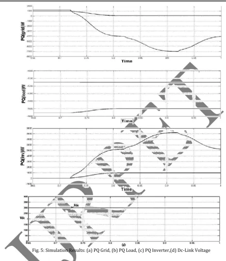
Fig. 5: Simulation Results: (a) PQ Grid, (b) PQ Load, (c) PQ Inverter,(d) Dc-Link Voltage
Initially the grid-interfacing inverter is not coupled to the network. Therefore before t=0.72 s, the grid current profile in Fig. 3 (a) is matching to the load current profile of Fig. 3(d). At t=0.72 s, grid interfacing inverter is coupled to the network. At this moment inverter starts injecting the current in such a manner that the profile of grid current starts changing from unbalanced non-linear to the balanced sinusoidal current as shown in Fig 3(b). Also the grid interfacing inverter in addition supplies the load neutral current demand, the grid neutral current (In) becomes near to zero value after t= 0.72 s.
At t=0.82 s, active power generated from RES
NOVATEUR PUBLICATIONS International Journal of Research Publications in Engineering and Technology [IJRPET] ISSN: 2454-7875 VOLUME 3, ISSUE 7, July-2017
105 |
P a g e
grid interfacing inverter during different operatingcondition is keeping at constant level. Thus from simulation results, it is clear that the grid interfacing inverter can be efficiently used to compensate the current unbalance, current harmonics, load reactive power in addition to active power injection generated from RES.
IV. CONCLUSION:
Single phase non-linear load between phase c and neutral, single phase linear load between phase a and neutral and three phase nonlinear load is connected to load. Harmonic distortions at phase a, phase b and phase c currents at point of common coupling before inverter is in operation are observed as 13.22%, 26.12%, 16.13% respectively. After inverter is in operation, it is observed that highly unbalanced grid currents, after inverter acting as Active Power Filter, appear as pure sinusoidal balanced set of currents on grid side. And grid current side THD’s are reduced to 1.72%, 1.44%, 1.94% for a, b and c phases respectively. For a three phase four wire DG system this paper presents a novel control of an existing grid interfacing inverter to improve the quality of power at PCC. The grid interfaced inverter with this proposed approach can be utilized to:
i) Injecting real power generated from RES to the grid, and/or,
ii) Work as a shunt Active Power Filter (APF).
Thus it eliminates the use of additional power conditioning equipment to improve the power quality at PCC. The extensive MATLAB simulations have validated the proposed approach and it is shown that grid interfaced inverter can be utilized as multi-function device. The current harmonics and current unbalance due to unbalanced and non-linear load coupled to PCC are compensated effectively in such a way that grid side currents are at all times maintained as balanced sinusoidal.
REFERENCES:
1) J. M. Guerrero, L. G. de Vicuna, J. Matas, M. Castilla, and J. Miret (Sep. 2004.) “A wireless controller to enhance dynamic performance of parallel inverters in distributed
generation systems,” IEEE Trans. Power Electron., vol. 19,
no. 5, pp. 1205–1213,
2) .J. H. R. Enslin and P. J. M. Heskes (Nov. 2004.)
“Harmonic interaction between a large number of distributed power inverters and the distribution network,”
IEEE Trans. Power Electron., vol. 19, no. 6, pp. 1586– 1593.
3) U. Borup, F. Blaabjerg, and P. N. Enjeti (Nov./Dec. 2001) “Sharing of nonlinear load in parallel-connected
three-phase converters,” IEEE Trans. Ind. Appl., vol. 37,
no. 6, pp. 1817–1823.
4) P. Jintakosonwit, H. Fujita, H. Akagi, and S. Ogasawara (Mar./Apr. 2003) “Implementation and performance of cooperative control of shunt active filters for harmonic damping throughout a power distribution system,” IEEE Trans. Ind. Appl., vol. 39, no. 2, pp. 556– 564.
5) J. P. Pinto, R. Pregitzer, L. F. C. Monteiro, and J. L. Afonso(2007) “3-phase 4-wire shunt active power filter
with renewable energy interface,” presented at the Conf.
IEEE Rnewable Energy & Power Quality, Seville, Spain. 6) F. Blaabjerg, R. Teodorescu, M. Liserre, and A. V. Timbus (Oct. 2006)“Overview of control and grid synchronization for distributed power generation
systems,” IEEE Trans. Ind. Electron., vol. 53, no. 5, pp.
1398–1409.
7) J. M. Carrasco, L. G. Franquelo, J. T. Bialasiewicz, E. Galván, R. C. P. Guisado, M. Á. M. Prats, J. I. León, and N. M. Alfonso (Aug. 2006) “Powerelectronic systems for the grid integration of renewable energy sources: A survey,”
IEEE Trans. Ind. Electron., vol. 53, no. 4, pp. 1002–1016. 8) B. Renders, K. De Gusseme, W. R. Ryckaert, K. Stockman, L. Vandevelde, and M. H. J. Bollen (Jul. 2008)
“Distributed generation for mitigating voltage dips in
low-voltage distribution grids,” IEEE Trans. Power. Del., vol.
23, no. 3, pp. 1581–1588.
9) V. Khadkikar, A. Chandra, A. O. Barry, and T. D. Nguyen, (2006) “Application of UPQC to protect a
sensitive load on a polluted distribution network,” in Proc.
Annu. Conf. IEEE Power Eng. Soc. Gen. Meeting, pp. 867– 872.
10) M. Singh and A. Chandra, (2008) “Power maximization and voltage sag/swell ride-through capability of PMSG based variable speed wind energy
conversion system,” in Proc. IEEE 34th Annu. Conf. Indus.
Electron. Soc, pp. 2206–2211.
11) P. Rodríguez, J. Pou, J. Bergas, J. I. Candela, R. P. Burgos, and D. Boroyevich (Mar. 2007) “Decoupled double synchronous reference frame PLL for power
converters control,” IEEE Trans. Power Electron, vol. 22,