1140
Simulation Studies On Performance Analysis Of
Variable Frequency Induction Motor Drive And
Incipient Fault Diagnosis Using Wavelets
D Venkata Ramana, P.Chandrasekar, R.Sreedhar
Abstract: The advent of Power Electronic Devices capable of handling high currents, aided the design of Variable frequency drive (VFD) with Induction motor or inverter fed induction motor drive, which can be characterized by increased reliability and reduced cost. Though tak en care highly, such type of drive system is prone for different kinds of faults. When fault occurs, the drive operation has to be stopped if it is designed for general fault detecti on. The cost of this schedule can be high, and this justifies the development of incipient fault diagnosis. Finding the fault im mediately after it occurs is general method of diagnosing the fault. In this case the damage occurs to component or system. If the fault is detected just before it damages the component or system is much better than general fault diagnosis. i.e. diagnosing the fault at developing stage. It saves the system or component from damage. In turn the cost of damage is reduced. This is called the incipient fault detection. In this paper, general fault det ection as well as incipient fault detection using the wavelets has been simulated using MATLAB/SIMULINK package. Simulation results are presented showing both the general fault detection and incipient fault detection using the Wavelets.
Index Terms: Fast Fourier Transform (FFT), Insulated Gate Bipolar Transistor (IGBT), perfect reconstruction (PR), Sinusoidal Pulse Width Modulation technique (SPWM), Variable frequency drive (VFD), Voltage/Frequency (V/F). Wavelet Transform (WT).
—————————— ——————————
1
INTRODUCTION
Implementation of Induction motor, in industries, is used for constant speed operations, but not for variable speed operations. It would be most helpful to industries, if the induction motor is used for variable speed operations, because of its low cost, consistent performance and robust nature. But, the less efficiency and high cost penalty due to low Power factor must be improved when it is used for variable speed operations. The innovative devices in power electronics made speed control of induction motor effective and now they are acceptable in industries for wide speed variation applications with lessen making and maintenance cost. The Inverter fed induction motor drive is used for applications, where the control of the speed or torque is required [1-2]. Inverter controls the speed of the motor by changing the frequency of the input to the machine, thus the Induction motor will run at demanded speed. Mainly, it allows transformation of power from one frequency to another. Also, output frequency can be varied from 10KHz to 30KHz to vary speed for wide range. In diverse applications, such as, mine mills, oxygenating of huge buildings, air blowers which save energy by allowing air volume to match the demand of the application, pumps, the Inverter fed Induction Motor Drive is used. Also, this drive is used in industrial air grade compressors to save the energy consumed [3].
2
VARIABLE
FREQUENCY
DRIVE
OPERATION
The basic building block of Inverter fed Induction motor has AC-DC and DC to AC conversion and connected by DC bus. Whole unit displayed in fig.2.1, i.e. The three-phase full wave diode rectifier considered would convert 3- phase input AC supply into DC supply. The DC link connected at the output terminals of rectifier reduces the ripple contents in the DC output [4-5]. The three-phase inverter section consists of IGBT’s where the filtered DC supply is being converted into stepped AC supply, fed to the induction motor. It is renowned that the synchronous speed (Ns) of an Induction motor is subjected to the supply frequency [6-7]. Therefore, the speed of the motor can be controlled using VFD is given by,
Speed (rpm) (1)
Where; f = Frequency in Hz, p = Number of poles.
The Table. 2.1, shows the speed variation as frequency changes and it is represented as Frequency Vs speed curve in Fig.2.2, below.
Thus, speed of a motor can be conveniently adjusted widely with gradual change of frequency fed to the motor under the condition of constant poles. Pole changing method also gives speed change, but not in gradual change and it requires a physical change of poles to the motor. Therefore, the Inverter fed induction motor drive provides smooth and precise change in speed by changing in the frequency supplied to the motor through sinusoidal pulse width modulation technique (SPWM) implemented in the Inverter. By changing the frequency of the drive, the speed gets varied, so, the term VFD [8].
______________________________
• D.Venkata Ramana, Research Scholar, Electrical and Electronics Engineering, Vel Tech Rangarajan Dr. Sagunthala R&D Institute of Science and Technology, Avadi Chennai 600 062, India. Email : [email protected]
• P.Chandrasekar, Professor and Head, Electrical and Electronics Engineering, Vel Tech Rangarajan Dr. Sagunthala R&D Institute of Science and Technology, Avadi Chennai 600 062, India. Email : [email protected],
Fig2.1. Circuit Diagram of inverter fed Induction Motor Drive.
Table 2.1 Frequency variation and corresponding rotor Speed
Fig.2.2. The rotor speed Vs frequency curve.
3. CONSTANT
V/F
RATIO
OPERATION
Output voltage -to - frequency (V/f) ratio of all VFD maintains the constant, at all speeds to maintain magnetic flux not to get saturated.
The phase voltage V, frequency f and the magnetic flux Φ of
the motor are related by the equation: V = 4.444 f NΦm or
V/f = 4.444NΦm
Where, N = number of stator turns per phase. Φm = magnetic flux
If the input voltage fed is maintained constant as the frequency reduced, the magnetic flux would get saturated, which disturbs the motor performance. Therefore, to avoid the magnetic saturation the flux must be maintained fixed. Also, the torque of the motor is the interaction between stator flux and rotor flux, so, at variable speeds to maintain rated torque, the constant flux must be sustained at its rated value. This fundamental requirement is managed by keeping the (V/f) ratio unchanged, i.e. the voltage is reduced as the frequency is minimized to maintain the fixed (V/f) ratio, so that the magnetic core does not get saturated. A diode bridge and capacitor link is used to reduce the ripple content out of rectifier output, which, also to some extent eliminates harmonics. Due to PWM technique, output current waveform is closely matches with the source line current, which helps in minimizing the temperature. Fixed and closed to unity power factor will be maintained because of implementation of Sinusoidal pulse width modulation technique for reducing harmonics.
3.1. Variation OF Motor Speed
The bridge converter supplies DC power to the inverter drive, which is filtered by LC filters to get constant output waveform. Constant output waveform is essentially required for better performance of drive. Inverter output converts DC back to AC, and the inverter output voltage frequency and magnitude can be varied. This is done by using Insulated Gate Bipolar Transistor (IGBT).
3.2. Inverter with IGBTs
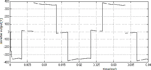
IGBTs are used for inverter control, i.e. at required specific intervals to switch the DC bus ON and OFF. The above operation produces variable AC voltage and frequency output, but output is not exactly pure sinusoidal in nature. So, IGBTs provide stepped AC output instead of sinusoidal waveform as shown in Fig.3.1. and in Fig.3. 2. If this supply is directly fed to the drive, it produces harmonics and drive performance gets degraded. This forces to use Pulse width modulation technique to reduce harmonics. It‘s important that it provides required variation of frequency and voltage to control the output parameters of motor. Pulse width modulation is most useful in varying the shape of non-sinusoidal waveform into approximately close to the sinusoidal waveform [8] as shown in Fig. 3.3.
Fig3.1. Single-phase Inverter Output Waveform Frequency (Hz) Speed(rpm)
Theoretical
Speed(rpm) Simulated
20 600 496
25 750 615
30 900 735
35 1050 870
40 1200 1000
45 1350 1130
1142 Fig3.2. Three-phase Inverter output waveforms
Fig.3.3. Inverter Output with SPWM
Drive DC bus voltage is switched ON and OFF during the pulse width modulation is called switching frequency or carrier frequency. The switching frequency resolution must be high to keep the higher pulse width resolution. In modern variable frequency drive 4 to 16Khz or 4000 to 16000 switches on/off per second can be used for carrier frequency range. But for higher carrier frequency range the heat developed in the machine is higher due to harmonics developed, which could be balanced to decrease the heat level. The carrier frequency range in IGBT inverter can be higher compared to SCR frequency range.
4.
MATHEMATICAL
MODELLING
OF
A
THREE-PHASE
VOLTAGE
SOURCE
AC 3-phase voltages with ωe (constant frequency), which is
filtered by LC filter and supplied to induction motor stator and is modelled using (2) to (4) as follows.
(2)
(3)
(4)
5. MODEL
OF
THE
INDUCTION
MOTOR
The induction motor is modeled using transformation of fixed a-b-c coordinates to rotating d-q-o coordinates. The equivalent circuit diagram of d-q-o coordination is shown in Fig.5.1. Formulated equations for 3-phase Induction Motor model has been given in the following equations [9].
Fig.5.1. d-q-o model of Induction Motor
From the above diagram, the following equations are obtained for the flux;
𝜑𝑞𝑠 = 𝐿𝑠𝑖𝑞𝑠 + 𝐿𝑚𝑖𝑞𝑟 ′ (5)
𝜑𝑑𝑠 = 𝐿𝑠𝑖𝑑𝑠 + 𝐿𝑚𝑖𝑑𝑟 ′ (6)
𝜑𝑞𝑟 ′ = 𝐿𝑟 ′ 𝑖𝑞𝑟 ′ + 𝐿𝑚𝑖𝑞𝑠 (7)
𝜑𝑑𝑟 ′ = 𝐿𝑟 ′ 𝑖𝑑𝑟 + 𝐿𝑚𝑖d𝑠 (8)
where 𝐿𝑠 = 𝐿𝑖𝑠 + 𝐿𝑚 (9)
𝐿𝑟 ′ = 𝐿𝑖𝑟 ′ + 𝐿𝑚 (10)
For the stator side,
𝑉𝑞𝑠 = 𝑅𝑠𝑖𝑞𝑠 + (𝑑/ 𝑑𝑡) 𝜑𝑞𝑠 + 𝜔𝑒𝜑𝑑𝑠 (11)
𝑉𝑑𝑠 = 𝑅𝑠𝑖𝑑𝑠 + (𝑑/ 𝑑𝑡) 𝜑𝑑𝑠 − 𝜔𝑒𝜑𝑞𝑠 (12) For the rotor side,
𝑉𝑞𝑟 ′ = 𝑅𝑟 ′ 𝑖𝑞𝑟 ′ + (𝑑 /𝑑𝑡) 𝜑𝑞𝑟 ′ + 𝜔𝑒 − 𝜔𝑟𝜑𝑑𝑟 ′ (13)
𝑉𝑑𝑟 ′ = 𝑅𝑟 ′ 𝑖𝑑𝑟 ′ + (𝑑 /𝑑𝑡) 𝜑𝑑𝑟 ′ − 𝜔𝑒 − 𝜔𝑟𝜑𝑞𝑟 (14) At this investigation, 𝑉𝑞𝑟 ′ and 𝑉𝑑𝑟 ′ are set to zero for a squirrel cage induction machine.
The generated electromagnetic torque is given as
𝑇𝑒 = 3P/4 𝐿𝑚(𝑖𝑑𝑟𝑖𝑞𝑠 − 𝑖𝑞𝑟𝑖𝑑𝑠) (15)
Where,
Lm Mutual Inductance
Lis Stator Leakage Inductance
L’ir Rotor Leakage Inductance
Iqs Q-axis component of the stator current
Ids D-axis component of the stator current
Iqr Q-axis component of the rotor current
Vds D-axis component of the stator voltage
Vdr D-axis component of the rotor voltage
ωr Rotating velocity of the Motor rotor in
electrical degrees Rr Rotor resistance
Idr D-axis component of the rotor current
φds D-axis component of the stator flux
φqr Q-axis component of the rotor flux
φdr D-axis component of the rotor flux
Vqs Q-axis component of the stator voltage
Vqr Q-axis component of the rotor voltage
ωe Rotating velocity of the applied two-phase
Q-D reference frame Rs Stator resistance
6. EFFECT
OF
CHANGE
IN
SUPPLY
VOLTAGE
ON
STARTING
TORQUE
(16)
Substituting E2 = supply voltage, V
Then, = (17)
Substituting, K3 = then
(18)
7. INVERTER
MODEL
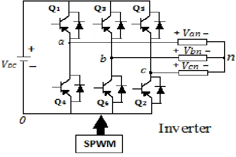
Fig.7.1. DC supply of from rectifier imparted to the inverter and modulated inverter output will be fed to the motor. The inverter transistor states switching model has been shown in Table.7.1. And care must be taken not to get turn on simultaneously the transistors in any single leg at any time of operation of drive.
Fig. 7.1: Three-phase Full–Bridge Inverter
i.e.
Q1 + Q2 (19)
Q3 + Q4 (20)
Q5 + Q6 (21)
Modulating technique is used in a 3-phase inverter and valid transistor states will be selected in order to generate required waveform.
States Q1 Q2 Q5 Vab Vbc Vca
1 0 0 0 0 0 0
2 0 0 1 0 -Vdc Vdc
3 0 1 0 - Vdc Vdc 0
4 0 1 1 - Vdc 0 - Vdc
5 1 0 0 - Vdc 0 - Vdc
6 1 0 1 - Vdc - Vdc 0
7 1 1 0 0 Vdc - Vdc
8 1 1 1 0 0 0
Table.7.1. The Transistor Switching States
(22) (23) (24) Pulse width Modulating signals are; Equations (22) , (23) and (24).
By combining the Equations (22) , (23) , (24) and (17), (18), (19) the following equations obtained:
(25) (26)
(27) Adding Equations (25) to (27) to give Equation (28);
(28) As we are dealing with balanced voltages, 𝑉𝑎𝑛 + 𝑉𝑏𝑛 + 𝑉𝑐𝑛 = 0, equation (28) becomes
(29)
Substituting for 𝑉𝑛𝑜 in Equations (22) to (24) gives: (30) (31) (32)
8.
COMPLETE MODEL OF INVERTER FED
INDUCTION MOTOR DRIVE
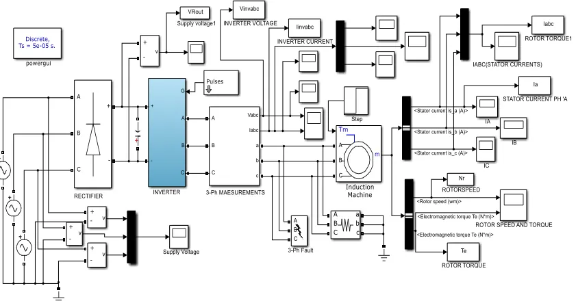
1144 Fig.8.1. Simulation model of Three phase Rectifier Inverter- Induction motor drive
The Fig.8.1 shows the Simulink model. Values used in simulation are given in Table.8.1.
Parameter Value
Supply Voltage 415volts (line) Supply Frequency 50Hz Rotor Type Squirrel Cage Motor
Rating 3kW
Number of poles 4
Normal speed 1500rpm
Table.8.1. Simulation Parameters
Fig.8.2. Rotor speed
VFD have the following advantages;
i, saves the Energy,
ii, draws Less current at starting,
iii, minimizes thermal and mechanical stresses on Motor and belts during starting,
iv, Easy to retrofit, and v, improved power factor.
Fig.8.3. Statorcurren ‘a’phase.
Fig.8.5. Rotor torque
9. FAULT
DETECTION
USING
WAVELETS
[1] Finding fault signals using FFT may be most useful due to its functioning in the frequency domain only. But, in Dynamic conditions, i.e real time fault detection in the drive or parts of drive is most important when load is continuously varying. For non-periodic, non-stationary, short duration fault signal, which is of impulse nature can be super imposed by the wavelet transform to find fault in real time. For the analysis of current transient phenomena, Wavelet Transform (WT) is a suitable one due to its ability to extract information from transient signals simultaneously in the time and frequency domain [10-11].The analyzed signal from the wavelets has been displayed in Fig.9.1. The de-noised signal of original stator current of induction machine drive is showing the fault magnitude and time of fault occurrence at the fault period of 0.01secs. Which makes the digital signal processor to decide to reconfigure or shut down the drive, else it might become catastrophic fault by causing larger damages and losses.Noise removal from the faulty signal is essential to confirm the faulty signal compared to the healthy signal. Also, which helps diagnose the fault even under light load conditions. Wavelet Transform (WT) is a most suitable tool for reducing noise from faulty signals due to its perfect reconstruction (PR) filters [12-13].
Fig.9.1. De-noised wavelet analysis for fault period 0.01s.
10. CONCLUSION
In case of fault occurrence, identifying the fault is most important, for the wavelet is favorable option from the simulation study of this paper. This simulation model can be used for further research to study behavior of the drive under the inverter faults, diagnosing these faults using advanced
monitoring techniques such as FFT and WTs and plan for necessary automatic control action. Also, can be investigated in detail for predicting the different faults at incipient level and by using the advanced signal processing techniques these faults can be diagnosed and the drive can be protected or reconfigured to avoid inadvertent shut down. This is an attempt to show that Wavelet detects the fault in shortest possible time duration.
11. REFERENCES
[1] Randall L. Foulke, Principles and Applications of Variable Frequency Drives NC AWNA. WEA Spring Conference New Bern, North Carolina Apr-2009. [2] Nitin Goel1, P.R. Sharma2, Suman Bala,
“Performance Analysis of SPWM Inverter Fed 3-Phase Induction Motor Drive Using MATLAB/Simulink” International Journal of Advanced Technology in Engineering and Science, Volume 02, Issue 06, June 2014, pp.183-192
[3] D Venkata Ramana, S Baskar, “Application of VFDs for improving energy efficiency of industrial grade air Compressors”, IJET17-09-02-267, 2017.
[4] Ned Mohan, Tore M. Unbalanced and William P. Robbins Power electronics (converters, application and design) third edition, John Wiley and sons INC. [5] P.C. Sen Power electronics McGraw- Hill Education
Private Limited, Second edition 2009.
[6] H Cotton. Text book of “Electrical Technology” 1945, PIMAN Company LTD.
[7] Stephen J. Chapman. Electric machinery fundamentals, third edition, McGraw- Hill Companies INC.
[8] B K Bose, “Modern Power Electronics and Drives” Prentic Hall-2002.
[9] Jimmie J. Cathey Electric machines, analysis and design applying MATLAB. McGraw- Hill Companies INC, 2001 edition.
[10]N. Saravanan, K. I. Ramachandran. “Incipient gear box fault diagnosis using discrete wavelet transform (DWT) for feature extraction and classification using artificial neural network (ANN)”Expert Systems with Applications: (Pergamon Press, Inc. Tarrytown, NY, USA). Vol. 37 Issue 6, Jun- 2010 PP. 4168-4181 [11]S.M. Shashidhara, P. Sangameswara Raju. “FPGA
Based Embedded System Development for Rolling Bearings Fault Detection of Induction Motor”IJRES,2(3), Nov-2013, pp. 127-134 (ISSN: 2089-4864)
[12]Rajesh Patil “Noise Reduction using Wavelet Transform and Singular Vector Decomposition” Eleventh International Multi-Conference on Information Processing (IMCIP-2015), 849 – 853, 2015.