e-ISSN: 2250-3021, p-ISSN: 2278-8719 Vol. 3, Issue 5 (May. 2013), ||V1 || PP 25-30
Speed Control of Induction Motor using PI and PID Controller
Madhavi L. Mhaisgawali , Mrs.S.P.Muley
Department of Electrical Engineering Priyadarshini College of Engineering Nagpur, 440016, India Head of Department of Electrical Engineering Priyadarshini College of Engineering Nagpur,440016, India.
Abstract: This paper based on the speed control of induction motor (IM) using proportional integral controller (PI controller) and proportional integral derivative controller (PID controller) with the use of vector control technique. The conventional PID controller is compared with the conventional PI controller for full load condition. MATLAB simulation is carried out and results are investigated for speed control of Induction Motor without any controller, with PI controller and with PID controller on full load condition.
Key words: Induction Motor, Conventional PI controller, conventional PID controller.
I. INTRODUCTION
Induction motors have much application in industry because of their low maintenance and robustness. The speed control of induction motor is more important to achieve maximum torque and efficiency. In recent years, the control of the induction motor drive is an active research area. And the technology has further advances in this field. Generally, the control and estimation of ac drives ware significantly more complex than that of dc drives, and this complexity increases to a large extent if the high performances are demanded. The need of variable frequency, machine parameter variations, and the difficulties of processing feedback signals in the presence of harmonics create this complexity.
Induction motor can be controlled with the help of conventional PI and PID controller with the use of vector control technique. Because of major advantages of vector control, this method of control will oust scalar control, and will be accepted as the industry-standard control for ac drives. PI and PID controllers are widely used in different industries for control of different plants and have a reasonable performance. The conventional PI controller increases the order of the system, improves damping, and reduces maximum overshoot, decreases bandwidth and increase the rise time. But the PI controller can never achieve perfect control, that is, keep the speed of induction motor continuously at a desired set point value in the presence of disturbance or set point change. Therefore, we need an advance control technique such as PID controller.
In this article we will discuss the conventional PI and PID controller, respectively. Finally we will present the simulation result for speed control of induction motor using PI and PID controllers and a brief discussion.
II. PI CONTROLLER
The PI controller (proportional integral controller) is a feedback controller. It drives the plant which is to be controlled with a weighted sum of error and the integral of that value.
Figure1. Basic block of PI Controller
Advantages and disadvantages:
(1) PI controller increases the order and the type of the system by one. It also causes the steady state error to reduce to the zero, which is not the case for proportional only control in general.
(3) The presence of derivative action may make the system steadier in the steady state in the case of noisy data. This is due to the derivative action which is more sensitive to the high frequency terms in the inputs. (4) The PI controlled system is less responsive to real (non-noise) in the absence of derivative action.
(5) Also the relatively fast alterations in state and the system will be slower to reach to the set point due to the absence of derivative action. Therefore so as to improve all the drawbacks of PI controlled system, we are using a derivative action i.e. PID controller which is used to minimize the settling time and to improve the steady state error.
III. PID CONTROLLER
The PID controller (proportional integral derivative controller) is widely used in industrial control system. A PID controller calculates an “error” value as the difference between the measured process variable and the desired set point.
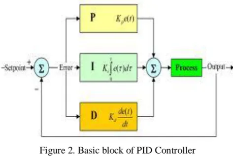
Figure 2. Basic block of PID Controller
The PID controller calculation involves three separate constants and is accordingly sometimes called three-term control i.e. the proportional, the integral and derivative value which is denoted by P, I and D.
A proportional controller may not give steady state error performance which is needed in the system. An integral controller may give steady state error performance but it slows a system down. So the addition of a derivative term helps to cure both of these problems.
IV. DEVELOPMENT OF THE SIMULINK MODEL
The speed performance of induction motor is checked first without any controller and then with the help of PI and PID controller. The simulink model is developed in the MATLAB which is shown in following Figures 3, 4 and 5.
Figure 4. Developed simulink model to check speed response of Induction motor with PI controller
V. SIMULATION RESULTS
Simulations are carried out in MATLAB environment and the results are verified for the speed v/s time on full load condition. The speed response of Induction motor is checked for without controller, with PI controller and with PID controller which is shown in Figure 6, 7 and 8.
Figure 6. Speed response of Induction motor on full load condition without any controller
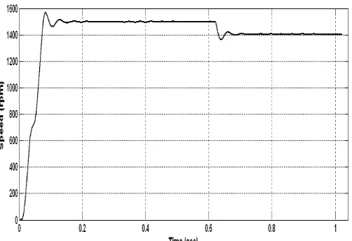
Figure 7. Speed response of Induction motor on full load condition with PI controller
The speed response of induction motor without any controller is shown in fig.6. This is for full load condition. When we applied a full load the speed suddenly decreases and is not stable. So as to improve the speed performance then we use the PI controller. Because of which the steady state error is eliminated and the rise time is improved but having overshoot and takes more time to settle shown in fig.7. Therefore the PID controller is used to improve the speed performance of Induction motor and the results are shown in fig.8.
VI. COMPARISION
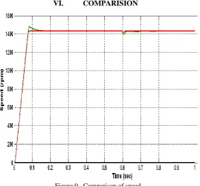
Figure 9. Comparison of speed
The main purpose of this paper is to control the speed of induction motor. So in the above figure 9, a comparison is shown. From this we come to know that PID controller is better than PI controller. The speed of induction motor using PID controller settled early than that of PI controller. The comparative results are also reported in the table below.
VII. CONCLUSION
Simulation is carried out in MATLAB environment for speed control of induction motor for full load condition, using PI and PID controller. And the results are checked and compared. From the comparison of speed of induction motor using PI and PID controller we conclude that, the PID controller gives better speed response in terms of settling time, rise time and steady state error.
VIII. APPENDIX
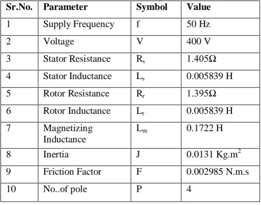
Table 2: Induction motor parameters Sr.No. Parameter Symbol Value
1 Supply Frequency f 50 Hz
2 Voltage V 400 V
3 Stator Resistance Rs 1.405Ω
4 Stator Inductance Ls 0.005839 H
5 Rotor Resistance Rr 1.395Ω
6 Rotor Inductance Lr 0.005839 H
7 Magnetizing Inductance
Lm 0.1722 H
8 Inertia J 0.0131 Kg.m2
9 Friction Factor F 0.002985 N.m.s
10 No..of pole P 4
REFERENCES
[1]. Bimal K.Bose, “Modern Power Electronics and AC Drives”, Pearson education . [2]. Gopal, M., “Modern Control System Theory”, 2nd ed., Wiley Eastern Ltd., 1993.
[3]. Krishnan, R. “Electric Motor Drives, Modeling, Analysis and Control”, 1st ed., Singapore: Pearson
Education, 2001.
[4]. R.Arulmozhiyal, Dr.K.Baskaran, “Speed Control of Induction Motor using Fuzzy PI and Optimization
using
[5]. GA”, International Journal of Recent Trends in Engineering, Vol 2, No.5, and November, 2009.
[6]. R. Arulmozhiyl, K.Baskaran “ Space Vector Pulse Width Modulation Based Speed Control of Induction Motor using Fuzzy PI Controller”, International Journal of Computer and Electrical Engineering, Volume 1, Number 1, 2009.
[7]. Pundaleek. B. H. , Manish G. Rathi, Vijay Kumar M.G.“ Speed Control of Induction Motor using PI and
Fuzzy Controller, IJCSNS , Volume 10, Number 10, October 2010.
[8]. Hossein Ebadi Kalhoodashti, Dr. Mehdi Shahbazian , “ Hybrid Speed Control of Induction Motor using