WWJMRD 2017; 3(11): 35-39 www.wwjmrd.com
International Journal Peer Reviewed Journal Refereed Journal Indexed Journal UGC Approved Journal Impact Factor MJIF: 4.25 e-ISSN: 2454-6615
Arkoalo Palchaudhuri Dept. of Telecommunication Engineering, M. Tech, 2nd year SRM University,
Kattankulathur, Chennai, India
C.T Manimegalai
Dept. of Telecommunication Engineering, Assistant Professor, SRM University, Kattankulathur, Chennai, India
Correspondence: Arkoalo Palchaudhuri Dept. of Telecommunication Engineering, Match, 2nd year SRM University,
Kattankulathur, Chennai, India
Performance Analysis of GSM & Bluetooth Operated
Programmed Security System in an Electric
Motorcycle
Arkoalo Palchaudhuri, C.T Manimegalai
Abstract
The time has come that people need to think about saving fuel seriously because burning too much of fuel can cause a large number of environmental pollutions. The concept of making the battery operated electric vehicle comes as a rescue. In one hand it helps to save fuels and on the other it helps in lowering the level of air pollution; which helps in improving the health condition of the populace. Even though several automobile manufacturers have introduced Hybrid Vehicles (hybrid vehicles generally utilize a traditional combustion engine and a fuel tank, as well as one or more electric motors and a battery pack).This paper is going to propose an electric motorcycle security system based on ARM microcontroller, 8051 microcontroller, Bluetooth and GSM communication which can be utilized both in Hybrid motorcycles and Electric motorcycles. When the proposed security features will be merged with those vehicles it will be an evolutionary concept in the world of next generation two-wheeler industry because besides lowering the level of air pollution and helping in controlling the use of fuel it mainly helps people to drive motorcycles safely.
Keywords: ARM7 LPC2148 Microcontroller, 8051microcontroller, Bluetooth module, GSM module, Ultrasonic and Proximity sensor, IR Eyeblink sensor, Alcohol sensor, Limit switch, Vibration sensor, Battery pack, DC motor etc
Introduction
From the last few decades India is expanding its automotive industrial frontier gradually. We have witnessed several improvements in the evolution of modern motorcycle manufacturing technology. As a result of various researches the automotive industries are now able to invent Hybrid Vehicles successfully and the companies are still working and doing research for making the vehicles more reliable, user friendly and secured. The increasing number of vehicles has caused several problems such as pollution, shortage of fuel and most importantly fatal crashes. As a solution the companies are trying to invent motorcycles which will use less amount of fuel such as Hybrid vehicles and electric motorcycles. By using these vehicles we can lower the usage of fuel and the level of air pollution but we do not have enough options for reducing the chance of accidents. Some security features are already introduced in the market with modern vehicles such as combined braking system (CBS), Electronic stability control, Anti-lock braking system (ABS), Intelligent speed assist (ISA), Blind Spot warning system and GPS. Identifying the vehicle‟s position is becoming easy by posing a bigger concern in the development of satellite communication technology. This project is going to make a compact programmed hardware module as a security feature in an electric motorcycle which will include ARM7 LPC2148 microcontroller, 8051 microcontroller, Bluetooth, GSM and some sensors. If the rider loses control this will help the vehicle to take some immediate decision automatically in order to avoid an accident. Besides this, if any object comes in front of the vehicle (within 100 centimeters), the motorcycle automatically will decelerate the speed of the vehicle using Ultrasonic sensor and moves towards it to avoid collision. And also the theft detection facility helps the owner of the motorcycle to lock the engine GSM module, if the vehicle gets stolen. Now a days riding in drunk condition during riding have become the most important and usual cause of
accidents. We are employing Alcohol sensor will lock the engine if anyone starts the motorcycle after consuming alcohol by detecting the vapor of alcohol. Even though any accident happens then an auto generated SMS which includes the location of the motorcycle will be sent to the family of the rider and to the accidental rescue team with the help of GSM module. Though some technologies are already introduced in market but all the features are not yet assembled together to make a smart electric motorcycle in a cost effective aspect.
In this paper column (II) is describing the methodology of the proposed system, column (III) is describing the block diagram of the proposed microcontrollers‟ connectivity layout, and column (IV) is describing the used softwares to assemble the hardware components, column (V) is
describing detailed specifications of implemented
hardwares, column (VI) contents conclusions and future works and column (VII) references.
Methodology
Two microcontrollers (ARM7 development board
LPC2148 & 8051 microcontroller) are going to be used in this proposed system; one of which will be attached with the helmet and another will be with the motorcycle. The microcontroller (8051), attached with the helmet, will have Bluetooth module, Infrared Eye-blink sensor and Alcohol sensor with it. And the microcontroller (LPC2148), attached with the motorcycle, will have Bluetooth module, GSM module, Ultrasonic sensor, Proximity sensor, Vibration sensor, Temperature sensor, LDR sensor, 12Volt DC motor (150 rpm), DC motor driver, etc. with it. Both the microcontrollers (One attached with the helmet and another with the motorcycle) will be connected through Bluetooth with each other. The user/rider can ignite or stop the engine (Motor) ignition by using an SMS consist of a password. This procedure can be categorized as an anti-theft facility which will make the motorcycle more secured so that no one can steal it.
Fig 1: Helmet and Motorcycle connectivity procedure
„Figure 1‟ describes the use of two microcontrollers- one of which is set into the helmet and another is set in the motorcycle and both are connected through Bluetooth, and a 12V DC geared motor which is working as an electric engine.
This proposed system will have also a limit switch which is placed in the top position inside the helmet. This limit switch is used for limiting the ignition of the engine which makes the user to wear the helmet. When the rider will wear the helmet the circuit will be closed and power will be transmitted to the microcontroller and when the rider will not wear the helmet the circuit will be opened and the power will not be transmitted to the microcontroller. If the circuit stays opened then the microcontroller placed in the helmet will not be able to connect via bluetooth with the microcontroller placed in the motorcycle to accept the ignition start password. If the rider puts off his helmet after igniting the bike will automatically get stopped. This procedure will motivate the rider to put on the helmet always during riding. Then the IR eyeball sensor will start its work that is monitoring the eyeballs of the rider continuously. If the rider falls asleep while riding the motorcycle or if the eyes of the rider suddenly get closed in any reason even then the sensor will decelerate the speed of the motorcycle and stop it. Ultrasonic sensor & Proximity sensor will continuously measure the distance and if the motorcycle goes out of control due to sudden arise of any object in front of the motorcycle and if the user stops his activity the sensor will decelerate and stop the engine to prevent the motorcycle to collide with the object in front of it. In any case if user collide with the object vibration sensor will sense the collision and send an auto generated SMS to the rescue center and family of the rider. Temperature sensor will measure the engine motor generated heat. If the motor gets hot and crosses limit, then it will inform the rider to put the engine off for cooling it. Sometimes at night the eyes of the riders get dazzled if the users of the vehicles‟ coming from the opposite side forget to adjust the light (upper/deeper) properly even the rider of a motorcycle can make the same mistake too and that can cause a fatal crash. LDR sensor controls its headlight focus system to make the upper/deeper automatically during riding at night. GSM module helps the system to operate the SMS facility properly. DC motor driver helps to control the DC motor. Alcohol sensor positioned in the helmet locks the engine if rider rides the vehicle after consuming alcohol by detecting the vapor of alcohol.
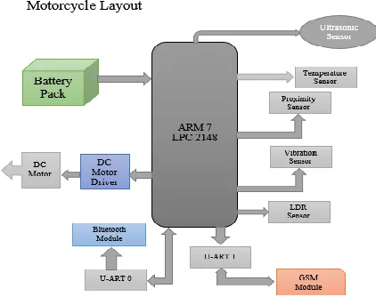
Proposed Microcontroller Connectivity Block Diagram
„Figure 2‟ contains an ARM 7 LPC2148 microcontroller board which is connected with some sensors(Temperature, Ultrasonic, Proximity, LDR, Vibration), DC motor driver, 12V DC motor, 12V 1.2Ah battery pack as an input power to the engine as well as to the microcontroller. There are also two U-ARTs one is for GSM module, and another is for Bluetooth module.
Fig 3: Microcontroller positioned into the helmet
„Figure 3‟ contains 8051 microcontroller which is connected with Alcohol sensor, IR Eye blink sensor, and a limit switch and 9V DC battery as a power supply to the microcontroller. U-ART is using to connect with Bluetooth module
Software Used
KEIL Programmer, Embedded C, Philips Flashing Utility, H-JTAG Debugging tool.
Hardware Implimentation
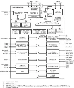
The used microcontrollers, i.e. ARM7 LPC2148 are based on a 32bit ARMTDMI-S CPU with true time emulation and studded trace support, that includes the microcontroller with interwoven high speed flash memory of 512KB. An interfaced wider memory of 128 bits and other than that a unique accelerator enabled 32 bit code execution at the ultimate clock rate. The substitute 16 bit thumb mode minimizes the code by more than 30% for the critical code size application. For their small size and low power consumption the LPC2148 microcontrollers are the best to apply where the minimization is required, such as access control and point of the scale. A good combination of serial communications interfaces ranging from a USB 2.0 full speed device, multiple UARTS(s), SPI, SSP to 12Cs and on chip SRAM of 8kb up to 40 KB, prepare these devices very well be fitted for communication gateways and protocol converters, soft modems, voice recognition and low end imaging, giving each a large buffer size and high processing power. Several 32 bit timers, Dual or single 10 bit ADC(s), 10 bit DAC, PWM channels and 45 fast GPIO lines with up to nine level sensitive exterior intermission pins coin microcontrollers particularly worthy for automations and galenical system.
Fig 4: LPC2148 Internal connection layout
(A) The HC-SR04 ultrasonic sensor utilizes sonar to figure out the amplitude of an object such as bats or dolphins do. It endeavors an exceptional range of veracity and immutable readings in an easy to use package. Its progression is not afflicted by sunlight or black metal like sharp range finders (though delicate materials such as cloth can be burdensome to find out). Akin in execution to the SRF005 but with the low price of a sharp infrared sensor. Its specifications are: Power Supply: 5V DC, Quiescent Current: <2mA, Effectual Angle: <15°, Ranging Distance: 2cm – 500 cm/1" - 16ft Resolution: 0.3 cm
(B) The eye-blink sensor functions by highlighting the eye and eyelid zone with the help of infrared light, then by tracking the distortions in the reflected light by applying a phototransistor and differentiator circuit. The distinct activity is based greatly on the fitting and aiming of the emitter and locator with respect to the eyes. The connectivity procedure of IR eye blink sensor is done first by connecting regulated DC power supply of 5Volts, Black wire is connected as ground, brown wire is output and the red is positive power supply. These wires are also marked on the PCB. To assess the sensor the rider needs power up the sensor by connecting two wires +5V and GND and the rider can leave the output wire as it is. When eyes will be closed, LED will be off and the output will be at 0Volt. If an eye blink sensor glass is set on the face within 15mm distance, rider can view the LED blinking on each eye blink. The output is highly active in the eye and for interfacing applications it can be given directly to the microcontroller. Some specifications are:
Operating Voltage: +5V DC regulated,
(C) SIM800 supports Quad-band 850/900/1800/1900MHz; it can convey voice, SMS and data information with very low power depletion. With the help of Bluetooth and Embedded AT; it permits total cost saving fast time to time market for customer applications. SIM800 modules are the enriched version of its earlier successful GSM/GPRS module series SIM900. SIM800 GSM modules include implanted Bluetooth stack compliant with 3.0+ EDR and FM Radio support, and the interface is attainable using AT commands SIM900, SIM900A modules operate from 3.2volts to 4.8volts supply range. Same AT commands are used generally for calls/SMS activity of SIM900 and can be used with SIM800 modules but SIM series have included AT command set for supporting extra features like Bluetooth.
(D) Bluetooth module is commonly used for a serial port replacement to build a relation between PC and the encapsulated project or between the microcontroller and the robotic things etc. The module can be built up for baud rates 1200 to 115200bps. Specifications are given below: Bluetooth Module HC-05 Features: Serial communications: 9600-115200bps SPP (Serial Port Profile) support UART, USB, PCM interface to host system Easy Configuration through AT Commands Encrypted connection Frequency: 2.4~2.524 GHz Bluetooth core V2.0 compliant Built-in Chip antenna Power Supply: 3.7-5V
(E) The primary vibration sensors host a piezo element and is used for flex, touch, vibration and shock measurement. A small AC and large voltage (+/- 90volts) is made when the piezo film changes its position back and forth. A simple resistor should get the voltage down to ADC levels. Can also be utilized for jolt sensing or a flexible switch. The piezoelectric transducer is disarranged from the neutral axis while vibration, it makes strains on piezo element which gives birth to voltage. The specifications are: Operating voltage 12v, DC Output is signal pulse whose amplitude is proportional to vibration. Frequency Range 0.5Hz to 20Hz., Operating voltage 12v DC Output is signal pulse whose amplitude is proportional to vibration, Frequency Range 0.5Hz to 20Hz.
(F) The proximity sensor includes an electromagnetic coil which is utilized to detect the existence of an object if it is metal/non-metal. Inductive proximity sensors are operated using an eddy current killed oscillator (ECKO) principle. This kind of sensor includes four elements like coil, oscillator, trigger circuit and an output. The oscillator is an initial capacitive tuned circuit that makes a radio frequency. The electromagnetic field created by the oscillator is shipped from the coil away from the sensor. The circuit includes enough feedback from the field to keep the oscillator active. When a metal target arrives at the field, eddy current circulate within the target. This creates a load
on the sensor declining the amplitude of the
electromagnetic field. As the target appeals the sensor, the eddy currents increase by increasing the load on the oscillator and further decreasing the amplitude of the field. The trigger circuit looks over the oscillators amplitude and at a level switches the output state of the sensor from its normal condition (ON/OFF). As the target parts away from the sensor, the oscillator amplitude increases. At the pre-decided level the trigger switches the output state of the
sensor back to its common condition. The output configuration three-wire, DC proximity sensor, can either be PNP (sourcing) or NPN (sinking). This specifies the type of transistor utilized in the output switching of the transistor. Some specifications are:
Operating Voltage : DC 6-24V range within Universal Output Type : PNP or NPN normally open three-line Detection object : metal objects
Detection distance : 4 mm Output Current : 300 mA Response Frequency : 0.5KH
Working temperature : Temperature range -30 ° - = 60 °, + 23 °, within+ (-) 15% detection distance
Temperature range : -25℃ to + 60℃ within + (-) 10% detection distance
Dimensions : 12 mm or 18mm screw diameter Cable length : about 115 cm
Material : Metal
(G) The MQ-135 alcohol sensor includes a tin dioxide (Sno2), a perspective layer inner aluminum oxide micro tubes (measuring electrodes) and a heating object interior of the tubular casing. The extreme face of the sensor is surrounded by a stainless steel net and the black side occupies the connection terminals. Ethyl alcohol exists in breath is oxidized into acetic acid while passing through the heating element. The resistance lessens with the ethyl alcohol cascade on the tin dioxide sensing layer. By using the external load resistance the resistant variation is changed into a suitable voltage variation. Some basic pin configurations of Alcohol sensor are:
The MQ-3 alcohol gas sensor consists of total 6-pins includes A, H, B and the other three pins are A, H, B out of the total 6-pins only 4 pins are used. For the heating purpose two pins i.e. A and H are used and for the ground and power the rest two pins are used. The sensor has a heating system within itself which is created with oxide, tin oxide. It has heat coils to produce heat, and thus it is utilized as a heat sensor.
(H) The working principle of an LDR is photo conductivity
supply for both the load and bridge rectifier is to be kept consistently for nonstop operation of the light sensor circuit. The sensor has a low resistance around 100Ω in the morning. So the power supply flows through the LDR and ground through the variable resistor. This is for the resistance provided by the light dependent resistor in the day time or when the light falls on the LDR, and then it is less compared to the resistance of the remaining part of the sensor circuit.
More components are required like
8051 Microcontroller
12V DC geared motor
DC motor driver (L293D)
Battery Pack (12V 1.2Ah)
Regulator (7805 & 7812)
LED Lights (GREEN & RED)
1K Resistor
Ribbon Cable
Power Adapter (12V 1AMP)
Temperature sensor (DHT-11)
Motorcycle chassis and wheel
Limit Switch
Helmet
Conclusion
All the hardwire components will be assembled with the help of embedded c and collect the results onwards. Then different results will be compared to improve the overall credibility of the proposed security system for electric motorcycle. The invention of electric motorcycles is no doubt an evolution in the world of automotive industry and is also getting popular day by day. These motorcycles save the natural fuel on a higher level. This is perhaps the main reason why electric motor cycles are getting popular among the new generation. In this project the proposed security system of the electric motorcycles will increase the self-confidence of the rider by providing a lot of security features and even if the rider would face any accident his current location will be automatically sent to the nearby hospital and his provided address. The rider even will be able to start or stop his motor cycle by just using a SMS. The motor cycle too will be able to avoid any type of accidents automatically. All these features will make the electric motor cycle more user-friendly. So it can be said that the invention of electric motorcycle is indeed a great evolution.
References
1. “Anti-Theft Tracking System and Security System for
Automobiles using GSM and ARM”, K. Sruthi, Mr. S. Ravi, Y. Kiran Scholar, Dept. of ECE, Arjun college of Technology and Sciences, Telengana, India, Vol 4, issue 1IJEDR 2016
2. “Eye Blink Controlled Robot Using EEG
Technology”, Abdul Lateef Haroon P.S, U.Eranna, Ulanganathan J, Raymond Irudayaraj I., Dept. of ECE, BITM, Billari, ISETE International Conference, 4th Feb, 2017(Bengaluru,India)
3. “Intelligent Vehicle Monitoring System using Wireless
Communication”, Dontha Supriya, Mrs. Mythili Devi, Mr. SK Saidulu, Prof B Kedarnath, Dept. of ECE, GNIT, Vol 2, Issue 8, IJARE, August 2015
4. “Implementation of Wheelchair Controller using
Eyeball Movement for Paralytic People”, A.Kamaraj, P.S. Tulasiram, J.J. Vasanth, Dept. of ECE, Mepco Schlenk Engineering College,Tamil Nadu, IJESRT, April 2013
5. “Performance Analysis of Controller Area Network