Design of Active and Reactive Power Control
Management for Fuel cell based Grid
Connected Systems
S.Hemalatha
#1, G. Kala Priyadarshini
*2,
K.Presilla Vasanthini
#3 #123Department of Electrical and Electronics EngineeringPrince Shri venkateswara Padmavathi Engineering College, Chennai, India
Abstract In order to explore the capacity of fuel cell units in distribution systems, their well-organized modeling is required. A dynamic model of a fuel cell generator system is developed in this paper. The model is built from the dynamics of each part with their interconnections. This abridged model is a useful tool for studying the various operational aspects of fuel cell. The reactive power compensation is a precise feature of fuel cell systems because it will be always very close to the point of usage of electricity. Typically the fuel cell is connected to the power system through a dc/ac converter, which is equipped with both voltage- and power-control loops. Control algorithm of the grid coupling inverter is possible to enable reactive power management of the fuel cell DG system. This paper presents a smart control algorithm of the fuel cell DG grid coupling inverter, which affords active/reactive power management capability for the DG unit. The model is developed in the MATLLAB/Simulink and implemented in Sim Power Systems library.
Keywords — Decentralized Generation (DG), Fuel cell, active power, Reactive power, PWM inverter grid coupling inverter.
I
Introduction
The use of renewable sources in power system is gaining popularity due to environmental concerns over burning fossil fuels to generate electricity. Technological advances in power electronics have created opportunities for renewable sources to be harnessed at the distribution level .With the use of power electronic interface converters, renewable sources can be connected directly to a distribution network or combined with other local generators and loads to form an independent power system [1]. Wind and photovoltaic (PV) power generation are two of the most promising renewable energy technologies. Fuel cell (FC) systems also show great potential in DG applications of the future due to their fast technology development and many merits they have, such as high efficiency, zero or low emission (of pollutant gases) and flexible modular structure[2]. The modeling and control of a hybrid wind/PV/FC DG system is addressed in this dissertation. Different energy sources in the system are integrated through an AC bus [3], [4]. Dynamic
models for the main system components, namely, wind energy conversion system (WECS), PV energy conversion system (PVECS), fuel cell, electrolyzer, power electronic interfacing circuits, battery, hydrogen storage tank, gas compressor and gas pressure regulator, are developed. Type of fuel cell have been modeled in this dissertation is solid oxide fuel cell (SOFC). Power control of a grid-connected FC system as well as load mitigation control of a stand-alone FC system is investigated [5]. Based on the dynamic component models, a simulation model for the proposed distributed generation system has been developed using MATLAB/Simulink. Selection of a DG system for reactive power compensation is not a trivial issue [6]. The main selection factors are:
i. The closeness to the point of electricity usage.
ii. The economic viability.
iii. The controllability and range of DG active power ratings.
exhibit wider ranges of operation in the high power region. Thus, they can be selected for a wider range of applications, when the distributed power demand is between a few kW to few tens of MW [9]. High cost and the fuelling fuel cell are still a major problem to be solved, since the production, transportation, distribution and storage of hydrogen is difficult [1], [2]. This paper presents a smart control algorithm of the fuel cell grid coupling inverter, which provides active/reactive power management capability for the fuel cell DG unit. Matlab/Simulink is used for modeling of the inverter controller with reactive power production capability. A test system is built with Simpower system blocks for validation of the controller
IIFUEL CELL DG SYSTEM ARCHITECTURE
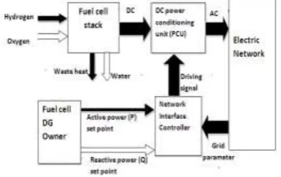
Fuel cells are electrochemical devices that convert the chemical energy of a reaction directly into electrical energy and heat [10]. A fuel cell operates by converting the chemical energy from reactants into electricity. As long as the fuel (such as hydrogen) and an oxidant (such as oxygen) is supplied, fuel cell stack will produce DC electricity (plus water and heat) continuously [11]. Fig.2 shows the Architecture of a generic fuel cell DG system. The power conditioning unit (PCU) is responsible for the conversion of dc to ac power according to the conditions that the network may require. The PCU is also controllable through the control signals. In this model architecture, the function of the network interface controller is to issue commands about the amount of real and reactive power P and Q respectively that is desirable to be injected to the network. This architecture structure can be valid for the majority of situations where the fuel cell DG interacts with a reasonably strong network [12].
Fig. 1. Architecture of a fuel cell DG system. An easy way to comply with the conference paper formatting requirements is to use this document as a template and simply type your text into it.
Supplying real power and constant reactive
power for load power factor improvement should be the normal operating mode of a fuel cell when connected to a strong grid that can be considered ―stiff‖. A stiff system will be influenced insignificantly by changes in the power production of the fuel cell plant, in terms of system voltage and
frequency. The dynamics of this mode will be determined by the FC plant rather than by the network [13].
III.FUEL CELL DGFOR POWER FACTOR
IMPROVEMENT
The intention of current control strategy is to inject the current according to the demanded active and reactive power amounts adjusted by the DG owner. The control phases are as follows: Measuring current at PCC, and transform to the required reference frame.
i. The DC/AC inverter synchronizes itself to the electric grid, using an appropriate synchronizer.
ii. A request of feeding active and/or reactive power by the DG owner into the electric grid, to establish the reference current values.
iii. The inverter connects the DG to the grid activates the current controller.
The most important control parameter is the grid current at the point of common coupling (PCC) [14]. Fig.2 illustrates the proposed current control strategy
To supply the required active and reactive power demanded by an inductive load from a grid connected fuel cell DG, the Instantaneous power theory [15], helps the design of a current control system, in the following steps:
A- Transformation of the measured current at the PCC from stationary to rotating frame: Using reference frame transformation, measured current signals at the PCC are transformed from (abc) stationary frame to (0dq) rotating frame. Any arbitrarily rotating frame can be chosen as the reference frame. The one used is with the q-axis is in phase with the phase a, as shown in Fig.4 [16]. In the chosen reference rotating frame the d-axis component represents reactive power, while the q-axis component represents active power.
coordinate system to the two-phase so-called αβ stationary coordinate system is done by the following equation: rbitrary rotating reference frame.
Fig.3. Arbitrary rotating reference frame
The transformation from the αβ reference frame to the rotating (dq0) frame is achieved by means of the following equation:
Where: ω is the synchronous angular frequency of the electric network. The DC components in the rotating (dq0) frame id and iq corresponds to the positive sequence fundamental components of iα and iβ. Since the dq transformation is the one that converts frequency dependent signals into ones with constant value, a three phase current values yields constant id and iq. The relation between the dq and active and reactive components depends on the selected frame of reference. To suppress noise and avoid transients in the measured current signals in dq frame, they have to be low-pass filtered.
B- Inverter synchronization to the electric grid: Synchronization of the fuel cell DG inverter with the electric grid voltage and frequency is achieved through the Phase Locked Loop (PLL) system. A PLL system is implemented in synchronous reference frame [18] as shown in fig 4.
Fig.4. Structure of the PLL system implemented in dq reference frame [19].
This type of PLL is able to provide the grid frequency information. The output phase provided by the PLL will be used as input into the PI controller in order to have an adaptive tuning in respect to the grid frequency [20]. The PLL controller plays an important role in this situation.
The regulator should be designed to respond with minimum of overshoot to the grid frequency and voltage variations. When the difference between grid phase angle θg and the inverter phase angle θinv is reduced to zero (Δθ = 0), the PLL become active and the lock is realized by setting the reference of the d-axis voltage to zero, following that:
=
=0 (4)The PLL PI controller parameters are the trade-off between a fast dynamic system providing quick synchronization and slow system providing filtered output [21]. The PI loop filter controls the oscillation frequency of the voltage controlled oscillator (VCO) with the sum of a voltage proportional to the error signal and a voltage proportional to the time integral of the error signal [22]. Therefore, under ideal grid conditions, this PLL structure performs satisfactory [19].
C- Active and/or reactive power set points by the DG owner to supply the load needs: ,
The filtered current signal in d and q directions are fed to two identical PI controllers to be regulated to the reference values. In order to make the system stable different cut-off frequencies has been calculated from the small signal models [17]. Filtering is done for the non-dc terms that appear in the signals. The lowest frequency is the mains frequency (50Hz), so in order to get a good estimation of the dc dq current components; the filter must provide attenuation for the mains frequency and
the above frequencies. The active and reactive power values expressed in the chosen rotating reference frame are calculated as follow [23]:
The active current reference value iq* is calculated from Eq.5 based on the active power set point P* impressed by feed forward path, which is less than or equal to the rated fuel cell DG power. The DC/AC grid connected inverter program the amount of reactive power by impressing a reactive power set point Q* in accordance with the load active/reactive needs:
--(6)
values in the dq frame are compared with the measured values at the PCC. The error signals are then fed to two identical PI controllers and the output is used as the control signals in the PWM generators. Before the control signals are sent to the PWM generators they are converted back to the stationary abc frame of reference using the inverse transformation of Eq.1 and Eq.2, in the following way:
Where fa ,* fb*, fc* are the commands in the PWM generators. In the following section modeling of the proposed controller is introduced
Selected parameters of the test system are summarized in Table.1.
The Simulink model of the PCU controller is illustrated in Fig.6. Where PI controller is concerned, the integral component the controller can lead to power factor correction.
TABLE 1
TEST SYSTEM COMPONENTS VALUES Simulation
time interval (sec)
Fuel cell DG active power set point (P*)
Fuel cell DG reactive power set
point (Q*)
0.00:0.25 0 0
0.25:0.35 100 kW 0
0.35:0.50 100 kW 120 kVAr
IV. COMPUTER MODELING AND SIMULATION
A complete Matlab/Simulink dynamic modeling is developed for the PCU control system described in this paper. The controller is used to drive the grid coupling VSI inverter to manage active power and reactive power for
Components Values
SOFC (fuel cell) rating 200kW DC link capacitor 1000μF Switching harmonic
filter inductance
5mH
Stiff grid voltage 415 V (rms) Stiff grid frequency 50Hz Load active demand 150kW Load reactive demand 120kVAr
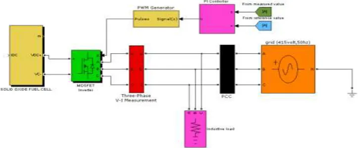
A generalized fuel cell DG Simulink model is built by the authors in [24] and used in this paper. The inverter and other test system based on Fig.5 are built using Simpower system blocks of Matlab [25],
Fig.5.Matlab model of the test system
the utility distribution system is modeled as a thevinin equivalent of a stiff (strong) grid.
Selected parameters of the test system are summarized in Table.1.
TABLE 1
TEST SYSTEM COMPONENTS VALUES
Simulation time interval (sec)
Fuel cell DG active power set point (P*)
Fuel cell DG reactive power set point (Q*)
0.00:0.25 0 0
0.25:0.35 100 kW 0
The Simulink model of the PCU controller is illustrated in Fig.6.
Where PI controller is concerned, the integral component the controller can lead to integrator windup resulting in instability of the controller [35], hence poor power management performance of the fuel cell DG inverter based system. The windup problem occurs when a system is subjected to a large disturbance, and the proportional controller (or actuator) in its attempt to correct the problem saturates ―full on.‖
Because the system can‘t provide as much output as is really needed, the error condition lasts longer than it theoretically should, but all this time the integrator is accumulating. Consequently, when the error is finally reduced, the large accumulated integral factor may cause the controlled variable to overshoot. A solution to this problem is to have the integral control section disconnected when the system is saturated [26]. This solution is called an integrator anti-windup circuit. A proposed circuit is with an extra feedback path provided of the absolute value of the controller output, to the integrator through a selection switch which passes through an error signal of zero when the controller absolute value is above the saturator upper limit, otherwise passes the error signal measured, as modeled in Fig.6.
Fig.8 Simulink model of PLL system with PI loop filter
The PI controllers would be tuned using MATLAB Single Input Single Output (SISO) tool [35] so that the desired dynamic
performance indices are met. Key parameters of the controllers are summarized in Table.2.
TABLE 2 PCU&PLL
PLL CONTROLLER
component value
Kp (Proportional term) 2 Ki (integral term) 1000
TABLE 3
FCDG OPERATION SCENARIO CONTROLLER PARAMETERS
PI CONTROLLER
component value
Kp (Proportional term) 0.2
Ki (integral term) 10
V. PROPOSED OPERATIONAL SCENARIO AND SIMULATION RESULTS
A simulation scenario of the fuel cell DG power grid connected system is proposed. The proposed scenario is used for the verification of the test system and controller modeling for FCDG active power production and reactive power control for power factor correction as seen by the utility at the PCC is summarized in Table.3. The simulation interval is 0.5 seconds.
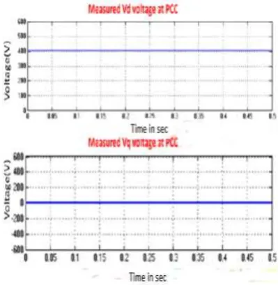
Fig.8. Measured dq voltage values at the PCC Testing of the operation of the designed and modeled PLL synchronizer is verified by measuring values of the dq voltage components, which is complied with the theory explained, as shown in Fig 6
Fig.9. Calculated dq reference current values For the current controller verification, the dq measured current values at the PCC is equal to the generated reference values, proving zero error of the controller, as shown in Fig.8.
Fig.10. Measured Id current values at the PCC The active and reactive power production and absorption at different operating points during the operation scenario are measured in Fig.12, and Fig.13. Power factor measurements are shown in Fig.15.
Fig.11. Measured active power (kW). Simulatio
n time interval (sec)
PF (grid) PF(fuel cell FCDG)
PF (load)
0.00:0.25 0.78 lag (not operating)
0.78 lag
0.25:0.35 0.4 lag 1 0.78 lag 0.35:0.50 1 0.65 lead 0.78 lag
Fig.13. Measured power factor. TABLE 4 PF MEASUREMENTS
Table.4 reports the power factor values as measured from Fig.14, with the proposed operation scenario. As, it could be concluded from Table.4, if the load is absorbing an active power and reactive power and no power is supplied by the fuel cell inverter, the utility grid reactive power and active power will be equal to the ones of the load, and the power factor as seen by the utility grid will be equal to that of the load (0.78 lag). However, when the fuel cell inverter starts to inject active power only (fuel cell unity power factor operation), clearly the active power supplied by the utility grid will decrease while the reactive power will be the same as before. At this condition, the power factor of the utility grid will deteriorate to 0.4 lag. To compensate for this deterioration and improve the power factor as seen by the grid, the inverter is programmed to supply active power and supply/absorb reactive power simultaneously. This is the final stage of the operational scenario, where a reactive power reference Q* should is included in the inverter control, according to Eq.6. In the simulation scenario Q* is made equal to QL, hence the utility grid power factor is equal to unity , and the fuel cell DG inverter power factor is changed to 0.65 lead.
CONCLUSIONS
Local reactive power management is essential for future networks using grid connected DGs. It is both technically and economically viable. Oversizing of the grid coupling inverter increases reactive power capacity of the DG system. Selection guidelines described in this
paper resulted in choosing the fuel cell DG as the most appropriate option for reactive power compensation. The instantaneous power theory concepts are applied for the design and modeling of the current control algorithm, which is used for DG
grid connection active/reactive power management. Models of the PI current controllers and the PLL synchronizer controller are designed and built using Matlab/Simulink. Through computer simulation of a proposed scenario, the controller design and modeling is verified, using a test system built with Simpower system blocks. Reactive power control capability should be the normal operating mode of fuel cell DG systems in addition to supplying active power. This operating mode would keep the utility power factor at the PCC equal to unity under different load conditions.
REFERENCES
[1] J. Redfield, Fuel cells: installation & operation as distributed generation assets‖. Southwest Research Institute.
Available at:
http://www.eere.energy.gov/de/pdfs/road_shows/austin_fuel cells. pdf
[2] U.S.-Canada Power System Outage Task Force Final Report on the August 14, 2003, Blackout in the United States and Canada: Causes and Recommendations, Joint US-Canada Power System Outage Task Force, April 2004, available at: http://www.nerc.com/pub/sys/all_updl/docs/blackout/ch1-3.pdf
[3] J.C.V.Quintero, ―Decentralized Control Techniques Applied to Electric Power Distributed Generation in Microgrids‖, PhD Thesis, Technical University of Cataluña, Spain, 2009.
[4] G. Joos, B. T. Ooi, D. McGillis, F. D. Galiana, R. Marceau, "The potential of distributed generation to provide ancillary services" , IEEE Power Engineering Society Summer Meeting, 2000.
[5] M. Braun, ―Technological control capabilities of DER to provide future ancillary services‖, International Journal of Distributed Energy Resources, vol. 3 no 3, 2007.
[6] M. Braun: ―Reactive Power Supply by Distributed Generators‖, IEEE PES General Meeting 2008, Pittsburgh, PA, USA, 20-24 July 2008.
[7] F. Barbir, "PEM Fuel cells: Theory and Practice", Elsevier academic press, 2005.
[8] Staff White Paper on: ―Stationary Fuel Cells for Power Generation‖, Prepared Pursuant to HB 2845 (77th Legislature), Commercialization of Fuel Cells. Available at:
www.puc.state.tx.us/electric/reports/scope/2003/app6fuel_cells.pd f
[9] S. Williamson, A. Emadi, M. Shahidehpour, ―Distributed Fuel Cell Generation in Restructured Power System‖, Power Systems, Proc. IEEE PES General Meeting, Denver (CO), USA, June 6-9, 2004.
[10] S.H. Chan, O.L. Ding, ―Simulation of a solid oxide fuel cell power system fed by methane‖, International Journal of Hydrogen Energy, 30(2), 2005.
[11] B. Gou, W.K. Na, B. Diong , "Fuel cells: Modeling, control, and applications", CRC press; Taylor and Francis, 2010.
[12] J. Padulles, G.W. Ault, J.R. McDonald, ―An integrated SOFC plant dynamicmodel for power systems simulation‖,
Journal of Power Sources (86) 2000.
[13] J. Padulles, G.W. Ault, and J. R. McDonald, ―An Approach to Dynamic Modeling of Fuel Cell Characteristics for Distributed Generation Operation‖, IEEE Power Engineering Society Winter Meeting, vol. 1, Las Vegas, NV, February 2000.
[14] S. Soter, F. Bertling , ―Adjustable Converter for Injection of Fuel Cell Power as a Part of a Virtual Power Plant‖, 35th Annual IEEE Power Electronics Specialists Conference, Aachen, Germany, 2004.
[15] H. Akagi, E. H. Watanabe, M. Aredes, ―Instantaneous Power Theory and Applications to Power Conditioning ‖,
[16] E. Acha, V. Agelidis, O. Anaya-Lara, T. Miller, ―power electronics control in electric systems‖, Newness publishers, 2002.
17] P. Karlsson, ―Stability of Voltage and Frequency Control in Distributed Generation on Parallel- Connected Converters Feeding Constant Load‖, EPE 2005, Dresden, Germany Sept. 12-14 2005.
[18] A.V. Timbus, M. Liserre, R. Teodorescu, F. Blaabjerg, ―Synchronization methods for three phase distributed power generation systems. An overview and evaluation‖,
Proceeding of the PESC‘ 05, 2005.
[19] A.V. Timbus, M. Liserre, R. Teodorescu, F. Blaabjerg, ―PLL algorithm or power generation systems robust to grid voltage faults‖, the Proceedings of 37th IEEE Power Electronics Specialists Conference, June 2006.
[20] N. Hamrouni, M. Jraidi, A. Cherif, ―New control strategy for 2-stage gridconnected photovoltaic power system‖,
Journal of Renewable Energy (33) 2008.
[21] L. N. Arruda, S. M. Silva, and B. Filho, ―PLL structures for utility connected systems,‖ Proc. of IAS‘01, vol. 4, 2001.
[22] S.K. Chung, ―Phase-Locked Loop for grid-connected three-phase power conversion systems ‖, IEE Proceedings on Electronic Power Applications, vol. 147, no. 3, 2000.
[23] C. Schauder, H. Mehta, ―Vector analysis and control of advanced static VAR compensator‖, IEE Proceedings Vol.140, No.4, July 1993.
[24] A.E. Hassan M.M. El-Saadawi K.M. Abo-Al-Ez M.S. Kandil, ―A Generalized Dynamic Model of A Fuel Cell System for DG Applications‖, in publish in Al- Azhar 11th Engineering Conference, 21-23 December 2010, Cairo, Egypt.
[25] The Math works documents. Available at: http://www.mathworks.com.