R E S E A R C H
Open Access
Network-coded retransmissions in wireless
demodulate-and-forward relay channels
Ye Liu
*and Chi Wan Sung
Abstract
Consider the case where a source wishes to reliably deliver a number of data packets to the destination with the help of a demodulate-and-forward relay. We discuss two retransmission schemes, each of which can ensure that the packets from the source will be delivered to the destination without error. We first discuss a scheme that combines signals from the source and the relay at the destination using a weighed combiner. The use of network coding which facilitates the retransmission process is then proposed. The generation of network-coded retransmission packets takes the qualities of previously erroneously received packets at the destination into account, and we show that such network coding scheme can make the retransmission process more efficient even if there is only one destination, unlike the existing approaches where the gain of network coding must come from coding opportunities across multiple destinations. Simulation results show that while the first retransmission scheme performs well in the low signal-to-noise ratio (SNR) region, the second scheme has good performance in both low and high SNR regions, thanks to the use of network coding. Moreover, the second scheme induces smaller packet decoding delay than the first scheme.
1 Introduction
1.1 Motivation and contribution
Relay has found itself becoming part of the long term evolution-advanced (LTE-A) due to its ability to extend coverage area and increase users’ throughput [1]. Forming a virtual antenna array with the source, works have been done (e.g., [2-4]) so that maximum possible diversity gain can be obtained when the relay works in different modes, namely decode-and-forward (DF), amplify-and-forward, and demodulate-and-forward (DmF). It has been demon-strated that with the help of relays, lower outage error probability can be achieved.
When multiple packets are to be routed to multiple des-tinations, network coding [5] has been proven to be an efficient solution in many network models. Works have been done to study the advantages of network coding in broadcast channels, including linear network coding [6-9] and non-linear network coding [10]. In DF relay chan-nels, outage analysis was performed in DF relay channels with two destinations in [11], where the use of network coding achieves full diversity with less bandwidth and energy. Retransmission schemes are then designed in [12]
*Correspondence: [email protected]
Department of Electronic Engineering, City University of Hong Kong, Kowloon, Hong Kong
for the same type of network, and network coding oppor-tunities of different lost packets are exploited among destinations, which greatly improves the throughput of the proposed schemes. A network-coded retransmission scheme of multiple sources multiple destinations with the help of a single relay is designed in [13], where the relay performs binary linear network coding on packets from different sources to increase throughput. The use of net-work coding in DmF multi-user multi-relay channels is also proposed in [14], where a relay is selected to for-ward network-coded packets by the realized channel gains of the source-to-relay links and relay-to-destination links, and a diversity of two is observed for each source.
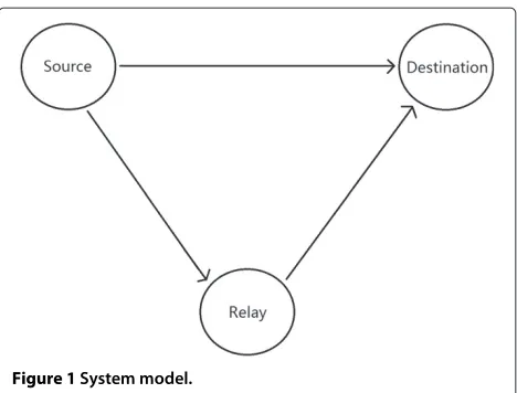
In this paper, we discuss the retransmissions of mul-tiple packets in wireless DmF relay channels shown in Figure 1, where the relay is limited to perform demod-ulation and re-moddemod-ulation to mitigate the large decod-ing delay in DF relays. We first design a retransmission scheme based on weighted combining. In this partic-ular scheme, the destination will use a weighted com-biner in [3] to combine signals from the source and relay after applying different weights on them. We then demonstrate how a network-coded packet generated by a DmF relay can help the destination to decode the erro-neous packets previously received from the source and
Figure 1System model.
propose a retransmission scheme using both network coding and weighted combiner. We seek for possibilities for the relay to perform network coding based on the signal-to-noise ratios (SNRs) of packets in error at the destination. Rules of forming network-coded packets are very easy to implement. Unlike [6-8] and [12], where the gain of network coding must have come from employ-ing multiple destinations, our approach can make use of network coding to achieve better performance even if there is only one intended destination. The attractive feature of the proposed network-coded retransmission scheme has a high potential to be extended to sys-tems with multiple destinations, which will be a topic for future investigations. Simulation results show that for different relay positions, the second retransmission scheme using network coding requires less retransmis-sions and has smaller packet decoding delay than the first scheme.
The rest of the paper is organized as follows. In Section 2, the system model will be set up and the weighted combiner will be briefly summarized. In Section 3, retransmission schemes based on the weighted combiner and network coding will be dis-cussed. After that, algorithms for finding network-coded packets will be proposed in Section 4. Simulation results will be given in Section 5. Finally, con-clusion and future works will be the content of Section 6.
1.2 Notations
Throughout the paper, we use boldface to represent a col-umn vector (e.g. Afor vector A) and math calligraphy to represent a set (e.g., B for set B). · denotes the Euclidean norm.(·)∗means the conjugate,(·)Tmeans the transpose, and(·)Hmeans conjugate transpose.xtakes
the floor of a real numberx.⊕denotes the bit-wise exclu-sive OR operation. Q(·) is the Q-function, andQ(x) :=
1 √
2π ∞
x exp(−t2/2)dt.
2 System model
Consider the relay channel displayed in Figure 1, where the source wishes to transmit its data to the destination via the help of relay. Transmissions are equally slotted in time, and the communication link between any two nodes in the network is modeled as block Rayleigh fading channel, where the real and imaginary parts of the channel coeffi-cients are i.i.d. zero mean Gaussian random variables with variance 0.5 and remain unchanged in a time slot. The received signals at the relay and destination are also cor-rupted by additive white Gaussian noise with zero mean andσ2variance. The relay and the destination have full knowledge of the channel state information of the source-to-relay channel and the source-to-destination channel, respectively, so that coherent detection can be performed. Assume the transmission power of the source and the relay is the same and is normalized to 1. With the realized complex channel coefficient to behfor a communication link, the SNR of a transmitted packet at receiver side is given by |h|σ22. We will usehSD, hSR, andhRD to indicate
the channel coefficient of the source-to-destination link, the source-to-relay link, and the relay-to-destination link, respectively. The relay is placed somewhere between the source and the destination, and the effect of path loss is taken into consideration.
The source has K source packets of equal number of bits to be transmitted reliably to the destination. All trans-missions, either from the source or from the relay, are assigned to different time slots of the same duration. We assume that a fixed-rate ideal channel coding scheme and binary phase-shift keying (BPSK) modulation is applied before sending a packet, where the channel coding scheme is ideal in the sense that decoding error is arbitrarily close to zero if the code rate is less than or equal to the chan-nel capacity. Given a realized SNR at the receiver, the rate log(1 + ) bits/s/Hz can be achieved [15]. For a given modulation scheme, the bit error rate (BER) after demodulation is directly related to. Therefore, to cor-rectly receive a packet, the BER after demodulation must be smaller or equal to a threshold value εth, so that the destination can correctly decode the packet.
packets, respectively, can be reliably received by intended receivers.
When there is no relay, the source can start the retrans-mission using chase combining-automatic repeat-request (CC-ARQ) scheme [16], where erroneous packets are repeatedly transmitted by applying the same channel cod-ing and modulation scheme. For a packet Pi that is in error after the initial phase, all available observations at destination are processed by maximal ratio combining (MRC) [17] so that the SNR values of the observations can be added. Once the sum of the SNR values exceeds the threshold value T, where
T =Q−1(εth)2, (1)
the retransmission ofPiwill be halted asPiis now reliably received.
If a relay is present, the relay can overhear the trans-missions in the initial phase and it may be helpful in the retransmission phase. Limited by its functionality, how-ever, the relay is not able to decode the original data packets from the source; hence, errors will be propagated to the destination if time slots are allocated to the relay in the retransmission phase. Nevertheless, ifPiis received at the relay with high SNR, then after demodulation and re-modulation, the BER of the re-modulated signal will be small. In that case, the relay is still able to provide useful information on the source packets and help achieve higher retransmission efficiency. A DmF relaying scheme is pro-posed in [3], where the destination applies a weighted combiner to the incoming signals from the source and the relay, such that a diversity of 2 is achieved. We now describe the relay scheme in [3] for future references.
Consider a symbol vectorXtransmitted from the source in the first time slot. Denote the received signals at the relay and the destination as YSR and YSD, respectively. The relay performs coherent maximal-likelihood demod-ulation onYSR. Denote the re-modulated signal vector at the relay asXR. For BPSK, theith symbol ofXRsatisfies
In the second time slot, the relay transmitsXR, and the destination receivesYRDfrom the relay. LetSD,SR, and
RDbe the SNRs ofYSD,YSR, andYRD, respectively. The combined symbol vectorYDcan be written as [3]:
YD=wSDYSD+wRDYRD, (3)
are the weights applied toYSDandYRD, respectively. In (5),εeq(SR,RD)is the equivalent BER of a signal at the destination after going through the source-to-relay link, being demodulated and re-modulated at the relay, and going through the relay-to-destination link. The expres-sion ofεeqis given as
It was shown in [3] that the above scheme can achieve the highest possible diversity. In the next section, we will design retransmission schemes based on the above weighted combiner.
3 Proposed retransmission schemes
In this section, we will discuss two retransmission schemes. One is based on the weighted combiner intro-duced in Section 2, and the other one uses both weighted combiner and network coding.
3.1 Cooperative retransmission
are packets at the destination that are not decoded cor-rectly. Let1,SD,2,SD, ...,K,SDbe the SNRs of packets 1, 2, ...,K at the destination after the initial phase, respec-tively. Let1,SR,2,SR, ...,K,SRbe the SNRs of packets 1, 2, ...,Kat the relay after the initial phase, respectively. The TCR scheme can be described as follows:
(1) For thei th packet,i∈[ 1,K]: Ifi,SD≥T, increment
i by 1. Ifi,SD<T, check the following conditions:
(a) i,SR<TR,
(b) i,SR≥TR.
(2) If condition (a) is satisfied: The source retransmits
Xi. The relay and the destination combine all
different copies ofXithey received from the source
using MRC, so thati,SRandi,SDare improved. The
source stops retransmission until eitheri,SR≥TR
ori,SD≥T. Go back to step 1.
3. If condition (b) is satisfied: The destination finds the required SNR of the receiving signal on the
relay-to-destination link, namelyi, such that
εD=εth. The calculation ofican be done by
applying bisection method to (7), after setting
εD=εth,SR=th,R,wSDhSD=σ2i,SD, wRDhRD= Q
−1[εeq( i,SR,i)]2
σ2 . The relay keeps
retransmittingXi,Runtil the destination has
combined enough observations ofXi,Rby MRC such
that the SNR of the combined copies ofXi,R, denoted
as Xi, is larger than or equal toi. Go back to step 1. To implement the TCR scheme, a counting-down method similar to [18] can be adopted. The destination will send ACKs and NACKs sequentially after the source broadcasts all its packets. If the destination sends an ACK for packet i, it will continue sending the control signal (either ACK or NACK) for packet i+1. If the destina-tion sends a NACK for packet i, it will stop and wait for retransmissions of packetiuntil it can issue an ACK for it. The source and relay can setup their own timers, and the timers are started upon receiving a NACK sig-nal from the destination. The initial value of the timer at the relay can be set according toi,SR. There will be two situations:
(1) Ifi,SR<TR, the source’s timer will expire first. The
source then starts retransmitting thei th packet until either an ACK signal is received from the destination wheni≥Tor an ACK signal is received from the
relay wheni,SR≥ TR. In the former case, the
retransmission of thei th packet is done. In the latter case, the relay will send an ACK to the source, and the retransmission of thei th packet will be
performed by the relay. The retransmission of thei th packet finishes until the destination issues an ACK.
(2) Ifi,SR≥ TR, the relay’s timer will expire first. The
relay sends an ACK to the source so that the source will not perform retransmission and then retransmits thei th packet until it receives an ACK from the destination.
Good values ofTRunder different channel settings will be obtained via simulations.
3.2 Network-coded cooperative retransmission
In this subsection, we first discuss how network-coded retransmission can be realized with the assumption that the relay has the correct versions of the pack-ets that the source wishes to deliver to the destination. We will then extend the idea to DmF relays, where the relay may not have exact copies of the source’s packets.
3.2.1 Network-coded retransmission
Assume that the source wishes to deliverP1andP2to the destination, and the relay has the two packets. After the initial phase, the destination cannot correctly decode the two packets. The two packets’ SNRs at the destinations are
1,SDand2,SD, respectively, where1,SD+2,SD ≥ T. Denote the received signals of P1 andP2 at destination after the initial phase asY1,SDandY2,SD, respectively. We have
Y2,SD = h2,SDX2+z
⇒ h
H 2,SD
hH2,SDh2,SD
Y2,SD = X2+
hH2,SD
hH2,SDh2,SD
z, (8)
where h2,SD is the channel coefficient of the source-to-destination link whenP2is sent by the source. We further assume that P1 ⊕P2 is transmitted by the relay and is correctly received by the destination. For ease of further development, we give the following definition of element-by-element multiplicationbetween two vectors of equal length.
Definition 1.Let denote the element-by-element
multiplication between two equal length vectorsAandB, whereAB = C,A =[a1,a2, ...,aL],B =[b1,b2, ...,bL],
C=[c1,c2, ...,cL], such thatci=aibi,i∈[ 1,L].
After correctly receivingP1⊕P2, the destination can perform the following: First, it encodes P1 ⊕ P2 into
X1⊕2 using the same channel coding and modulation schemes as the source’s, and then performs
element-by-element multiplication betweenX1⊕2and h
H 2,SD
hH2,SDh2,SDY2,SD.
Since BPSK modulation is applied and X1⊕2 is equal to
X1⊕2 h
We can see from (9) that by such a process, we come up with another noisy observation of P1. The SNR of this observation is equal to2,SD, since the magnitude of each component ofX1X2is equal to one, and the noise term’s power is unchanged. Next, the destination
com-binesX1⊕2 h
H 2,SD hH
2,SDh2,SDY2,SD andY1,SDtogether using the
MRC principle, and a noisy observation ofP1with SNR
1,SD + 2,SD is formed. By the previous channel cod-ing assumption,P1is now correctly received as1,SD+
2,SD ≥ T. WithP1andP1⊕P2,P2can be derived by the exclusive OR operation. From this example, it is illustrated that instead of simply repeating the two packets that the destination needs, the relay has an alternative: to transmit the network coded packet, under the condition that the sum SNRs of the two packets at destination is larger than T. The number of retransmitted packets is then reduced from two to one. The idea can also be extended to situa-tions when higher modulation schemes are used, which is discussed in Appendix 1.
In general, if 1,SD+ 2,SD+ · · · + m,SD ≥ T, the relay can sendP1⊕P2,P1⊕P3, ...,P1⊕Pmto the des-tination. The destination will have m− 1 more copies ofP1with SNRs2,SD,3,SD, ...,m,SDonce it receives all the network-coded packets correctly. Combining all them copies ofP1(the underlying assumption is that the relay getsP1correctly in the initial transmission) with MRC will lead to successful decoding ofP1, and thenP2,P3, ...,Pm
can be derived. We term such a combination ofmpackets’ SNRs as avalid m-wise combination.
3.2.2 Network-coded retransmission in DmF relay networks
In a DmF relay, as decoding is not performed, the re-modulated signal may contain errors. Nevertheless, it is still possible for a DmF relay to forward network-coded packets, and it is also possible for the destination to decode the network-coded packets from the relay cor-rectly, which is demonstrated in the following:
Consider the transmission of two packets P1 and P2. After the initial phase, the destination hasP1’s SNR1,SD andP2’s SNR2,SD, where1,SD < T,2,SD < T, and
1,SD+2,SD ≥T. The relay has observations ofP1and
P2with SNRs1,SRand2,SR, respectively. After demodu-lation and re-modudemodu-lation, the relay hasX1,RandX2,R, and then the network-coded symbol vectorX1,RX2,Rcan be
formed. Note thatX1,RX2,Ris essentially a noisy
obser-The above equation indicates that now the relay has a noisy observation ofP1⊕P2with SNReq(1,SR,2,SR). The relay retransmitsX1,RX2,R, and the destination gets a noisy observation of it with SNR RD. At this point, we can also say that the destination has a noisy observa-tion ofP1⊕P2 with SNReq(eq(1,SR,2,SR),RD). If
eq(eq(1,SR,2,SR),RD) ≥ T, then we can say that
P1⊕P2is correctly received by the destination.
In order to ensure that the network-coded packetX1,R
X2,Rcan be decoded correctly by the destination, the BER ofX1,RX2,Rat the relay must be smaller than or equal toεth; otherwise, the BER of the packet received by the destination will never be smaller than or equal to εth, even if the relay-to-destination is noise-free. Therefore,
eq(1,SR,2,SR)in (10) must be no smaller thanT. This imposes the following constraint on1,SRand2,SR:
1,SR>T,
2,SR>T, (11)
due to the reason that for finite1,SRand2,SR,
eq(1,SR,2,SR) <min(1,SR,2,SR). (12)
increasing function of2,SR. We can then infer (12) from (13) and the monotonicity of (14).
Inspired by (10), to ensure that the relay can provide any necessary network-coded packet that can be ultimately received by the destination correctly, it is desirable to set a threshold valueat the relay, namelyTR,NC, and make sure that each requested packet by the destination has SNR larger or equal toTR,NC at the relay. The value ofTR,NC must be larger than T by (11). After setting TR,NC, the required realized SNR of a network-coded packetat the destination, namelyNC, can be found by
eq(NC,TR,NC)=T
⇒ {Q−1{[ 1−Q(NC)]Q(
TR,NC)+[ 1
−Q(TR,NC)]Q(
NC)}}2=T
⇒ NC= {Q−1[
Q(√T)−Q(TR,NC) 1−2Q(TR,NC)
]}2.
(15)
In the situations where 1,SD + 2,SD < T, send-ing X1,R X2,R will not be able to help the destination decode P1 or P2 correctly. However, as Q(1,SR) ≤
Q(TR,NC) < εth, the relay has a good enough observa-tion ofP1and thus able to help the destination correctly receivingP1 by retransmitting the demodulated and re-modulated version ofP1(i.e.,X1,R). In general, the relay can help the destination correctly receivingPiby retrans-mitting Xi,R, if i,SR ≥ TR,NC. The required SNR of received Xi,R at the destination, namely i, can be cal-culated by applying bisection method to (7) as in the TCR scheme. GoodTR,NCvalues under different channel settings will be obtained via simulations.
In general, if1,SD+2,SD+· · ·+m,SD≥Tandi,SR≥
TR,NC,i∈[ 1,m], the relay can retransmitX1,RX2,R,X1,R
X2,R, ...,X1,RXm,R, each of which must be received by the destination with SNR larger than or equal toNC.
We now propose the threshold-based network-coded cooperative retransmission (TNCCR) scheme, which will be initiated if there are packets that are not correctly received by the destination after the initial phase:
(1) ForPi,i∈[ 1,K]such thati,SD<T, if
i,SR <TR,NC, then the source retransmitsPiuntil
i,SD≥Tori,SR≥TR,NC. Let(a1,a2, ...,ak)be
thek -tuple consisting of all the SNRs at the destination that are less thanT, wherek≤K. (2) Find valid combinations in(a1,a2, ...,ak). Let
VCmbe the number ofm-wise valid combinations
found, wherem∈[ 2,ω](i.e., there exists aω-wise valid combination that is formed by the sum of most SNRs among all valid combinations). Starting from
the smallestm, where VCm>0, the relay
retransmits the network-coded packets corresponding to one of them-wise valid
combinations. Each of the network-coded packets is repeatedly retransmitted until its SNR exceedsNC.
(3) ForPi,i∈[ 1,K]that are neither involved in any valid
combinations nor received reliably at the destination, the relay retransmitsPiuntil the SNR ofPiexceeds
i.
The implementation of TNCCR can be done as follows:
(1) ForPithat is not correctly received at the destination, do the following: the destination broadcasts a NACK for the packet. Upon receiving the NACK ofPi, the relay checks whetheri,SR<TR,NC. If it is the case,
then the relay sends a NACK, and the source will start retransmittingPi. The source stops sendingPiif it
receives an ACK from the relay (wheni,SR ≥TR,NC)
or an ACK from the destination (wheni,SD≥T).
(2) If there are still packets not correctly decoded at the destination, the destination will look for valid combinations. For thei th valid combination, the destination sends a signal requesting the
corresponding network-coded packet(s) with specific indices to the relay. The relay will retransmit the corresponding network-coded packet until the SNR of that packet exceedsNC.
(3) After receiving all the required network-coded packets correctly, the destination requests the relay for each of the packets that is neither involved in a valid combination nor received correctly.
3.2.3 Delay consideration
We now consider theaverage packet decoding delay[19] of different retransmission schemes, which is an important measure for applications where the sequence of decod-ing packets does not matter (i.e., multiple-description coding). We first give the definition of packet decoding delay:
Definition 2. The packet decoding delay of a source
packet is the number of retransmissions before it is cor-rectly decoded at the receiver.
The following example demonstrates how packet decoding delay is computed.
Example 1.Consider a relay network using TNCCR as its retransmission scheme, whereK = 6,1=2= 0.5,
3 = 4 = 5 = 1/3,6 = 0, andT = 1. Assume
the packet decoding delay forP1andP2is 1. To decode
P3,P4, andP5, the destination has to wait for 3 retrans-missions (i.e., the retransmission ofP1⊕P2,P3⊕P4, and
P3⊕P5), so the packet decoding delays forP3,P4, andP5 are all equal to 3. The packet decoding delay forP6is 4.
In general, let the destination request retransmission of P1, P2, ..., Pn, where Pi, i ∈[ 1,n] can be a source packet (i.e.,Pr,r∈[ 1,K]) or a network-coded packet (i.e.,
Pr⊕Pk,r,k ∈[ 1,K]). Upon reception ofPi,i ∈[ 1,n],li source packets can be decoded. LetPi,i ∈[ 1,n] requires
μiretransmissions before being correctly received by the destination. Starting fromi =1, the destination will only requestPi+1if Pi is received correctly. Thetotal packet decoding delayis given as
l1μ1+l2(μ1+μ2)+ · · · +ln n
i=1
μi, (16)
and theaverage packet decoding delayis
l1μ1+l2(μ1+μ2)+ · · · +lnni=1μi n
i=1li
, (17)
whereni=1liis the number of source packets that can be decoded after receivingP1,P2, ...,Pn.
Example 2.Following Example 1, the average packet decoding delay of retransmittingP1⊕P2,P3⊕P4,P3⊕P5, andP6through error-free channels can be calculated as
2×1+0×2+3×3+1×4 2+0+3+1 =2.5,
suggesting that, on average, the receiver needs to wait for 2.5 retransmissions before decoding a packet.
Next, we show that under some specific conditions, the scheduling of retransmitting network-coded packets in TNCCR is optimum.
Proposition 1.Assume that for each i ∈ 1,K, where
i < T,i,SR ≥ TR,NC, and only pairwise and three-wise valid combinations are considered. When the retransmis-sions are error-free, the scheduling of retransmitting pack-ets in step 2 of TNCCR leads to the minimum average packet decoding delay.
Proof.See Appendix 2.
The general scheduling problem that minimizes the average packet decoding delay is however involved and is out of the scope of this paper. In the next section, we will discuss algorithms for finding valid combinations at the destination. The problem is in general hard and requires
high computational complexity. We will show the com-plexity of the problem and then propose some efficient algorithms.
4 Algorithms searching for valid combinations After step 1 in TNCCR, we still havekpackets yet to be decoded at the destination. Without loss of generality, we assumeP1, P2, ..., Pk are still in error at the destination. The problem of finding the maximum number of valid combinations can be stated as follows:
givenW= {1, 2, ...,k},i<T,i∈[ 1,k] max t,
subject tot∈Z+,
S1∪S2∪...∪St∪B=W,
Si∩Sr= ∅, 1≤i<r≤t, (18) Sk∩B= ∅, 1≤k≤t,
i∈Sr
i ≥T, 1≤r≤t,
whereBis the set that contains indices of packets which cannot find themselves involved in any valid combina-tions. To illustrate an instance of the above problem, suppose1=1.5,2=1.2,3=0.8,4=0.5,5=0.2, andT =2. One solution can beS1= {1, 4},S2= {2, 3}, andB = {5}, so thatt = 2. This means that instead of retransmittingP1,P2, ...,P5, we can retransmitP1⊕P4,
P2⊕P3, andP5, such thatt=2 transmissions are saved. The problem in (18) is actually equivalent to the bin-covering problem (or dual bin-packing problem) [20], where the bin-covering problem is defined as packing items of various sizes from a given set into bins so that the maximum number of bins are used, subject to the constraint that each bin must be filled to at least a given threshold. The problem is NP-hard, which means there is no polynomial-time algorithm available to solve it. The upper bound ontin (18) is
Upperbound#Valid_Comb.=
i∈Wi T
. (19)
It is easy to see that (19) gives the maximum number of valid possible combinations and sometimes overestimates it. For example, let1 = 2 = 1.8,3 = 0.4,4 = 0.1, andT=2. In this case, only one valid combination can be found inW= {1, 2, 3, 4}, while (19) gives the value 2.
4.1 Pairwise combinations only
We reduce the complexity of (18) by adding one more constraint, namely, we only concentrate on finding com-binations of SNRs that involve two elements. The formal statement of the simpler problem is the following:
givenW= {1, 2, ...,k},i<T,i∈[ 1,k] ,v=2, max t,
subject toS1∪S2∪...∪St∪B=W,
Si∩Sr= ∅, 1≤i<r≤t, (20) Sk∩B= ∅, 1≤k≤t,
i∈Sr
i≥T, 1≤r≤t,
1<|Si| ≤v,∀i∈[ 1,t] .
Before we develop algorithms for finding valid combi-nations, we first present a lemma that can help design efficient algorithms.
Lemma 1.There is an optimum solution for (20), where arg maxi{i|i ∈ W}is involved in a valid combination, if there exists at least one valid combination.
Proof. Letl = arg maxi{i|i ∈ W}. If there is an opti-mum solution that does not uselin any valid combination, then swapping lwith any element involved in any valid combination found will not affect the optimality of the solution.
Inspired by Lemma 1, we may first find a valid pairwise combination involving the largest element inW. If such a valid combination is found, we can start looking at the second largest element inWand try to find a valid com-bination involving it. The details of the algorithm are the following:
Algorithm 1 Find pairwise valid combinations Input: W= {1, 2, ...,k},1,2, ...,k,T.
Output: S1, S2, ..., St1, B, where
S1S2...St1
B=W. 1: =(1,2, ...,k).
2: Sort in descending order, then = (a1,a2, ...,
ak).
3: i=1,r=N,c=0. 4: whilei<rdo
5: ifai+ar ≥Tthen
6: c=c+1,Sc= {ai,ar} 7: i=i+1, r=r−1 8: else
9: r=r−1
10: end if
11: end while
At the end of Algorithm 1, we can represent W as W = S1S2...ScB, where Si, i ∈[ 1,t1] is a set that contains indices of packets involved in a pairwise valid combination, and |Si| = 2, B is the set that con-tains indices of packets not involved in any pairwise valid combination.
Theorem 1.Algorithm 1 maximizes t in (20).
Proof. Assume that for a givenW, there is at least one valid combination. Also, assume that{a1,aq}is found as
a valid pairwise combination by Algorithm 1.
From Lemma 1, we know there is an optimum solu-tion, where a1 is involved in a valid combination. Let {a1,ap}be a valid combination in the optimum solution.
Ifap=aq, then Algorithm 1 has found the valid combina-tion in the optimum solucombina-tion. Otherwise, ifap=aq, from the mechanism of Algorithm 1,aq will be the smallest
element, such that {a1,aq} can form a valid
combina-tion, so thatap ≥ aq. In this case, swappingap with
aqwill not affect the optimality of the solution.
The analysis above is carried over to other valid combi-nations found by Algorithm 1 after{a1,aq}.
Since each valid combination chosen by Algorithm 1 does not affect the optimality of its final solution, we con-clude that Algorithm 1 can find an optimum solution of (20) whenv=2.
The complexity of Algorithm 1 isO(KlogK), since the sorting in the second step has complexity of O(KlogK) and other steps has complexity of O(K). It should be noted that when the retransmission is error-free and only pairwise valid combinations are considered, TNCCR with Algorithm 1 will have the least num-ber of retransmissions it can ever achieve. The design of an optimum scheme when the retransmissions are subject to fading in terms of number of retransmis-sions is, however, involved and out of the scope of this work.
4.2 Pairwise and three-wise valid combinations
Now, we focus on the case where v = 3 in (20), which means we consider pairwise and three-wise combinations. We first prove that the decision version of the problem is NP-complete by reduction from a NP-complete problem called three-partition [21], and then discuss a heuristic algorithm for it.
The decision version of (20) can be stated as follows: Instance:knumbers1,2, ...,kand the corresponding indices setW= {1, 2, ...,k}, wherei<T, i∈[ 1,k].
For future reference, we call this problemv -cardinality-constrained bin-covering (v-CCBC). The three-partition problem is described for ease of reference [21]:
Instance: A finite setAof 3melements, a boundB∈Z+, and a ‘size’s(a)∈Z+for eacha∈A, such that eachs(a) satisfiesB4 <s(a) < B2and such thata∈As(a)=mB.
Question: Can A be partitioned into m disjoint sets S1,S2, ...,Sm, such that for 1im,a∈Sis(a)=B?
Theorem 2.3-CCBC is NP-complete.
Proof.We wish to solve the three-partition problem instance using the algorithm solving 3-CCBC. LetW = 1, 2, ..., 3m, and i bes(a), where 1 i 3manda ∈ A. Also, letT = B. Then, solve the 3-CCBC problem. If the answer is YES, then we find m subsets of W as
B
4 < i< B2, which implies that we can findmsubsets of Aof the three-partition problem satisfying the respective constraints. Similarly, if the answer is NO, then we can-not findmsubsets ofAthat satisfy the constraints. The reduction from three-partition to 3-CCBC is obviously in polynomial time, so that 3-CCBC is NP-hard.
As an output of the algorithm of 3-CCBC can be verified in polynomial time, 3-CCBC is in NP. Thus, 3-CCBC is NP-complete.
The above theorem implies that achieving the mini-mum number of retransmissions using TNCCR when the retransmissions are error-free and if pairwise and three-wise valid combinations are allowed would have exponen-tial complexity, which is impractical to implement.
We now focus on solving 3-CCBC by a heuristic. The idea of the algorithm is the following: First, apply Algorithm 1 to find pairwise combinations. Then, letUbe a set that contains elements inWthat are not involved in any pairwise combinations, search for three-wise combi-nations inU. The searching for three-wise combinations similar to Algorithm 1 is as follows: We first search for a valid combination involving the largest element inU. Then, find two other elementsi andr, such that the sum SNR of these two elements is the smallest, while the sum SNR ofi, r, and the largest element is larger than or equal to T. The same approach is carried out until no more valid three-wise combinations can be found. The details of the algorithm for v = 3 is presented inAlgorithm 2.
In step 7 of Algorithm 2, Algorithm 1 can be used to find x1andx2, such thatx1 +x2 ≥ T −b1 by changing
the while-loop condition to ‘no valid combination found yet’ andTtoT−b
1. After running Algorithm 2, we have S1, S2, ..., St1, where each of them has indices of SNRs
that form a valid pairwise combination. S1, S2, ..., St2, where each of them has indices of SNRs that form a valid three-wise combination.Bcontains indices that the
Algorithm 2 Find pairwise and three-wise valid combinations step; otherwise, go to the last step.
7: Find two elements, namely x1 and x2, in
(b2,b3, ...,bk−2t1), such thatx1+x2 ≥ T−b 1.
If no suchx1 +x2 can be found, go to the last step.
Otherwise, go to the next step. 8: t2 = t2+1,St2 = {b
corresponding SNRs are not involved in any valid combi-nations.
The complexity of the first step in Algorithm 2 is O(KlogK). The complexity of the other steps isO(K2), since for eachb
i, it takes a number of steps linear toKto
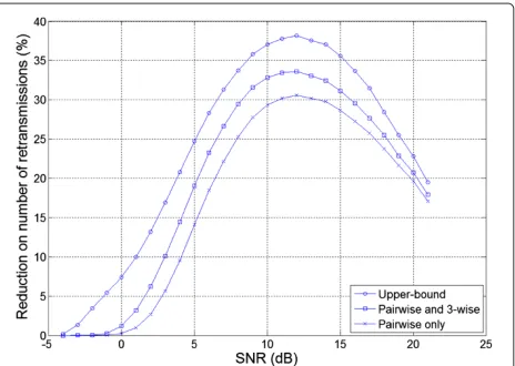
complete step 7; step 7 can be executed for at mostK3 times. So, in total, the complexity of Algorithm 2 isO(K2). Figure 2 shows the number of valid combinations found by Algorithms 1 and 2, whereK = 16. The upper bound on the number of valid combinations is also plotted. It can be seen that by executing Algorithm 1 or Algorithm 2, which are of very low complexity, near-upper bound performance can already be achieved.
Figure 3 displays the performance of TNCCR when the source-to-relay link and relay-to-destination link are noise-free. εth is set to be 10−3. Again, TNCCR with Algorithm 2 attains most of the gains which resulted from network coding.
In Figure 4, the upper bound on reduction of number of retransmissions using TNCCR is plotted whenεthis still 10−3, and the transmission power over noise power is 12 dB. The upper bound on reduction of number of retrans-missions can be calculated as k−Upperbound#Valid_Comb.
k . It
can be seen that the gain of TNCCR increases with the number of packets from the source.
5 Simulation results
Figure 2Comparison of the number of valid combinations found by Algorithms 1 and 2 with the upper bound.
applied to search for valid combinations. We simulate the retransmission performance in two scenarios:
Scenario 1 (Scn-1): The relay is positioned closer to the source, as displayed in Figure 5a.
Scenario 2 (Scn-2): The relay is positioned at the middle point between the source and the destination, as displayed in Figure 5b.
In the simulations, we take path loss into account. The path loss (in dB) can be calculated as 10αlog10(d), where
α is the path loss exponent and is set to be 4, and d is the distance between the sender and the receiver. We set the distance between the source and the destination to be 1, and the relative distances of source-to-relay and relay-to-destination in the two scenarios are shown in Figure 5. In Scn-1, the average channel gain power of the source-to-relay channel is 20.915 dB larger than that of the
Figure 3Performance of TNCCR when source-to-relay link and relay-to-destination link are noise-free,εth=10−3.
Figure 4Performance of TNCCR when source-to-relay link and relay-to-destination link are noise-free,εth=10−3and SNR = 12
dB.
source-to-destination channel, and the average channel gain power of the relay-to-destination channel is 6.196 dB larger than that of the source-to-destination channel. In Scn-2, the average channel gain power of the source-to-relay channel and the relay-to-destination channel are both 12.04 dB larger than that of the source-to-destination channel.
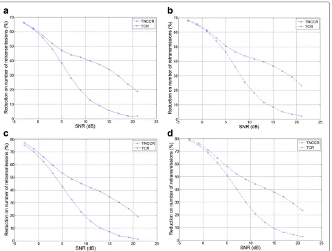
Figure 6 shows the performance comparisons between TCR and TNCCR in the aforementioned scenarios, where the percentages of reduction on the number of retrans-missions using different relay retransmission schemes compared to the CC-ARQ scheme without relay are plot-ted.εthis set to be 10−3and 10−4. Good threshold values for TCR and TNCCR in different situations, obtained through extensive simulations, are listed in Table 1. It can be seen that when the SNR is low, TCR and TNCCR have about the same performance. On the other hand, TNCCR has better performance when SNR is relatively high (7 dB or above). The implication of the observations is two-fold:
(1) At low SNRs, where there are few valid combinations (as implied by Figure 2), there will be few
retransmission of network-coded packets from the relay. In this case, TCR and TNCCR are more or less the same.
(2) At high SNRs, the relay in TNCCR starts
retransmitting more network-coded packets as there are more valid combinations. The results suggest that network-coded retransmissions are more efficient than non-network-coded retransmissions in the SNR region concerned.
Figure 5Two different positions of the relay studied in this work.(a) Scn-1, (b) Scn-2.
can be seen that TNCCR can save more retransmissions if more packets from the source are to be transmitted, which is similar to the observation of Figure 4.
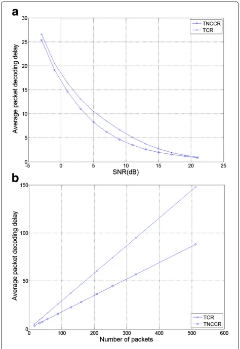
Figure 8 shows the average packet decoding delay of TCR and TNCCR schemes in Scn-2, where εth is set
to be 10−3. The results indicate that TNCCR scheme has less average packet decoding delay than the TCR scheme, which means that the destination experiences smaller delay in the retransmission phase before decoding a source packet using TNCCR.
Figure 6Comparisonn of MTCR against TCR and TNCCR in different scenarios.(a)εth=10−3in Scn-1, (b)εth=10−4in Scn-1, (c)εth=10−3
Table 1 Threshold values at relay of different retransmission schemes in different scenarios
Threshold value Scenario Retransmission scheme Threshold at relay
Scn-1 TCR 12.10
εth=10−3 TNCCR 11.15
Scn-2 TCR 10.20
TNCCR 10.35
Scn-1 TCR 15.48
εth=10−4 TNCCR 15.08
Scn-2 TCR 14.38
TNCCR 13.98
6 Conclusions
In this paper, we addressed the retransmission issue in DmF relay channels. We first designed a retransmission scheme based on a weighted combiner. By forwarding high-quality observations, the relay was able to help the system achieve high retransmission efficiency in low SNR region. Then, on top of the weighted combiner, another retransmission scheme based on both weighted combiner and network coding was proposed. The network-coded packets were formed according to the qualities of the pre-viously erroneously received packets at the destination, and they were able to boost the retransmission efficiency at high SNR region.
A possible future direction based on this work may consider a more sophisticated retransmission scheme that is based on incremental-redundancy hybrid auto-matic repeat request or IR-HARQ, i.e., by considering whether or not the qualities of the packets at the destina-tion can help the relay to decide how parity bits should be generated from which source packets so that system throughput can be increased.
The proposed scheme also has the potential to be applied in wireless broadcast channels. As it has been
Figure 7Reduction in the number of retransmissions using TNCCR in Scn-2.
demonstrated in 3.2, a network-coded packet generated by considering the SNRs of the received packets at the destination can be used to decode two packets. If the SNRs of the received packets at the destination is not considered (i.e., treat packets in error as erasures), then a network-coded packet can only be used to decode one packet if it is instantly decodable [8]. It is therefore expected
Figure 8Average packet decoding delay in Scn-2 when
εth=10−3.(a) Delay as a function of transmission power over noise
that the proposed network-coded retransmission scheme can result in higher throughput if the network-coded retransmissions are restricted to be instantly decodable. It is also interesting to investigate the possible perfor-mance improvement brought by the proposed scheme if a retransmitted packet is not required to be instantly decodable but innovative [9].
Appendices Appendix 1
Extension to higher modulation schemes
We first demonstrate that network-coded retransmis-sion can be applied when M-PSK modulation is used. We will see that the idea of network-coded retrans-mission presented in Section 3.2.1 is applicable when the signal constellation of the applied modulation scheme forms a group. From this observation, we can say that network-coded retransmission can also be applied to QAM, as the signals of QAM form a group [22].
M-PSK Consider the following signal constellation ofM -PSK, where each point in the constellation is given by ej2πβ/M(whereβ∈[ 0,M−1] andj2= −1).
Assume that two signals (namely X1 = ej2πβ1/M and
X2=ej2πβ2/M) are transmitted, whereβ1, β2∈[ 0,M−1]. The two signals are corrupted with additive noise (unlike the other sections where fading is present in the channel, here we only assume there is additive noise for simplicity) and the received signals areY1=X1+n1andY2=X2+n2, respectively. We now wish to send a network-coded signal that can provide information aboutX1andX2.
The M-PSK signal constellation can be related to the following finite Abelian group [23]:
UM{ej2πβ/M,β ∈[ 0,M−1]}, (21)
which is closed under the operation of complex multipli-cation. Let the inverse ofX1andX2be−X1 = ej2πβ Denote• as complex multiplication. If the signal X3 =
(−X1)•(−X2)is delivered to the receiver without noise, then at the receiver we can have
X3•Y1 = ej2πβ
We can see from (22) that an extra observation ofX2can be obtained fromX3•Y1. Similarly, an extra observation of
X1can be obtained fromX3•Y2. The MRC principle can then be applied to combine multiple noisy observations.
QAM From the above discussion, it is evident that the network-coded retransmission scheme can be applied to a modulation scheme if the signals form a group. In [22], it has been proven that the signal constellation of 22n -QAM is given by the group of units in the quotient ring Z[i]/2n + 2ni, where n is a positive integer and Z[i] means Gaussian integers ring. Similar derivations to (22) can be used to show that the network-coded retransmis-sion is applicable to QAM signals.
Appendix 2
Proof of proposition 1
Let the relay retransmitP1,P2, ...,Px through an error-free channel to the destination, where upon receivingPi, i∈[ 1,x],lisource packets can be decoded at the destina-tion. Since we only consider pairwise and three-wise valid combinations,li∈ {0, 1, 2, 3}.
Lemma 2.Letα,SD,β,SD, andγ,SDform a three-wise valid combination and, in order to decode source packets, Pα,Pβ,Pγ,Pi, andPrshould be retransmitted, where i,r∈ [ 1,x]. Then, a retransmission sequence which retransmits Pi followed by Pr has smaller average packet decoding delay than a retransmission sequence which retransmits other packets in betweenPiandPr.
Let the total packet decoding delay of sequences (1), (2), and (3) bed1, d2, andd3, respectively. We have
Lemma 3.Let la1 =2and la2 =1, where a1,a2∈[ 1,x]. Then, retransmittingPa1followed byPa2has smaller aver-age packet decoding delay than retransmittingPa2followed byPa1.
Proof. The average packet decoding delay of retransmit-tingPa1 followed byPa2 can be calculated as 1×22++21×1 =
4
3. The average packet decoding delay of retransmitting
Pa
2 followed byP
a1 can be calculated as
1×1+2×2 1+2 = 53. The lemma then follows.
Lemma 4. Let la1 =2, la2 =0, and la3 =3so that three source packets can be decoded upon receivingPa
2andP a3. Then, retransmittingPa1 first gives smaller average packet decoding delay than retransmittingPa2andPa3first.
Proof. The average packet decoding delay of sendingPa1
first is 1×2+2+2×0+0+33×3 = 2.2. The average packet decoding delay of sendingPa2 andPa3 first is1×0+0+2×3+3+23×2 = 2.4. The lemma then follows.
Lemma 5.Let la1 = 0, la2 = 3, and la3 = 1 so that three source packets can be decoded upon receiving Pa
1 andP
a2. Then, retransmittingP
a1 and P
a2 first gives smaller average packet decoding delay than retransmitting Pa
3first.
Proof. The average packet decoding delay of sendingPa 1
andPa2 first is1×0+0+2×3+3+13×1 = 2.25. The average packet decoding delay of sendingPa
3first is
1×1+2×0+3×3 0+3+1 =2.5. The lemma then follows.
The above lemmas together suggest the following: To minimize the average packet decoding delay in error-free retransmissions, network-coded packets (each of which can be used to decode two source packets) should be retransmitted first, followed by pairs of network-coded packets (each of which can be used to decode three source packets), followed by source packets. Therefore, TNCCR gives the minimum average packet decoding delay when the retransmissions are error-free and for each
i,SD < T,i,SR ≥ TR,NC, wherei ∈[ 1,K]. That proves Proposition 1.
Competing interests
Both authors declare that they have no competing interests.
Acknowledgements
This work was partially supported by a grant from the University Grants Committee of the Hong Kong Special Administrative Region, China (Project No.: AoE/E-02/08). Part of the work was presented in Wireless Advanced 2011.
Received: 4 January 2013 Accepted: 21 April 2013 Published: 25 May 2013
References
1. IF Akyildiz, DM Gutierrez-Estevez, EC Reyes, The evolution to 4G cellular systems: Lte-advanced. Phys. Commun.3(4), 217–244 (2010) 2. J Laneman, D Tse, G Wornell, Cooperative diversity in wireless networks:
efficient protocols and outage behavior. IEEE Trans. Inf. Theory.50(12), 3062–3080 (2004). doi:10.1109/TIT.2004.838089
3. TR Wang, A Cano, GB Giannakis, JN Laneman, High-performance cooperative demodulation with decode-and-forward relays. IEEE Trans. Commun.55(7), 1427–1438 (2007)
4. S Borade, L Zheng, R Gallager, Amplify-and-forward in wireless relay networks: rate, diversity, and network size. IEEE Trans. Inf. Theory.53(10), 3302–3318 (2007). doi:10.1109/TIT.2007.904774
5. R Ahlswede, N Cai, SYR Li, RW Yeung, Network information flow. IEEE Trans. Inf. Theory.46(4), 1204–1216 (2000)
6. D Nguyen, T Tran, T Nguyen, B Bose, Wireless broadcast using network coding. IEEE Trans. Vehicular Technol.58(2), 914–925 (2009). doi:10.1109/TVT.2008.927729
7. L Keller, E Drinea, C Fragouli, inFourth Workshop on NetCod. Online Broadcasting with Network Coding, (2008), pp. 1–6.
doi:10.1109/NETCOD.2008.4476183
8. P Sadeghi, R Shams, D Traskov, An optimal adaptive network coding scheme for minimizing decoding delay in broadcast erasure channels. Eurasip J.Wireless Commun. Netw (2010). doi:10.1155/2010/618016 9. HY Kwan, K Shum, CW Sung, Generation of innovative and sparse
encoding vectors for broadcast systems with feedback. IEEE ISI Proc, 1161–1165 (2011). doi:10.1109/ISIT.2011.6033715
10. QA Li, SH Ting, CK Ho, Nonlinear network code for high throughput broadcasting with retransmissions. IEEE ISIT, 2853–2857 (2009). doi:10.1109/ISIT.2009.5205268
11. C Zhi, C Wei, PY Fan, K Ben Letaief, inIFIP International Conference on NPC. Relay Aided Wireless Multicast Utilizing Network Coding: Outage Behaviour and Diversity Gain, (2008), pp. 358-364.
doi:10.1109/NPC.2008.22
12. PY Fan, C Zhi, C Wei, K Ben Letaief, Reliable relay assisted wireless multicast using network coding. IEEE J. Selected Areas Commun.27(5), 749–762 (2009)
13. QT Vien, LN Tran, EK Hong, Network coding-based retransmission for relay aided multisource multicast networks. Eurasip J. Wireless Commun. Netw.2011, 643920 (2011)
14. TW Yune, D Kim, GH Im, Opportunistic network-coded cooperative transmission with demodulate-and-forward protocol in wireless channels. IEEE Trans. Commun.59(7), 1791–1795 (2011). doi:10.1109/TCOMM.2011.050911.090660
15. D Tse, P Viswanath,Fundamentals of Wireless Communication. (Cambridge University Press, New York, 2005)
16. D Chase, Code combining–a maximum-likelihood decoding approach for combining an arbitrary number of noisy packets. IEEE Trans. Commun. 33(5), 385–393 (1985). doi:10.1109/TCOM.1985.1096314
17. JG Proakis,Digital Communications, 3rd edn. (McGraw-Hill, New York, 1995)
18. A Bletsas, A Khisti, DP Reed, A Lippman, A simple cooperative diversity method based on network path selection. IEEE J. Selected Areas Commun.24(3), 659–672 (2006)
19. P Sadeghi, M Yu, Instantly decodable versus random linear network coding: a comparative framework for throughput and decoding delay performance. CoRR (2012). doi:arXiv:1208.2387v1
20. SF Assmann, DS Johnson, DJ Kleitman, JYT Leung, On a dual version of the one-dimensional bin packing problem. J. Algorithms.5(4), 502–525 (1984) 21. MR Garey, DS Johnson,Computers and intractability : a guide to the theory
of NP-completeness. (W.H. Freeman, San Francisco, 1979)
22. J Rifa, Groups of complex integers used as qam signals. IEEE Trans. Inf. Theory.41(5), 1512–1517 (1995)
23. FR Kschischang, PG Debuda, S Pasupathy, Block coset codes for m-ary phase-shift keying. IEEE J. Selected Areas Commun.7(6), 900–913 (1989)
doi:10.1186/1687-1499-2013-136