Analysis of Combination of two Boost
converters for PV Battery System
Geethu Venugopal1, Saritha Sathyan2
PG Student [PE], Dept. of EEE, Sree Narayana Gurukulam College of Engineering, Kadayiruppu, Kerala, India1
Associate Professor, Dept. of EEE, Sree Narayana Gurukulam College of Engineering, Kadayiruppu, Kerala, India2
ABSTRACT: Solar energy is one of the renewable energies with highest potential. To use the solar energy efficiently, a battery storage system is usually added to balance the power difference between the PV generation and the load. In any PV system output may vary with time. In order to make the output constant, battery storage is added in the system. This paper proposes a new system, consist of two boost converters with a battery storage system for photovoltaic applications. In the two boost converter one is SISO and other boost converter is DISO. The proposed system has reduced number of switches. So switching losses reduces. It consists of four operational modes to achieve MPPT, battery charging and load regulation requirements. Experiment results are given to confirm the proposed converter.
KEYWORDS: Photo Voltaic system (PV system), Single Input Single Output (SISO), Dual input Single Output (DISO), Maximum Power Point Tracking (MPPT).
I.INTRODUCTION
Solar energy is probably the most important source of renewable energy available today. The mainly used solar energy system is the PV system. The advantage of this technique is that solar energy is directly converted in to electricity. The output of PV system is always varying with time. So we introduce a battery system. Plenty of topologies have been proposed to combine the PV array, the battery, and the load. This includes multistage converters, single stage converters and multiport converters, etc. Multistage converters include several power conversion stages such as DC-DC converters, DC-AC converters, Step up converters etc. between the PV and load of the system. Single stage converter achieves higher efficiency due to reduction of the number of switches and also it reduces power losses. Multiport converters are used to interface renewable resources, storage, and loads etc. It has several features like fewer components, faster response, MPPT and load regulation. Also we can either use isolated or non-isolated converters. Isolated converters have drawbacks of complex circuitry and control. But the isolated converters achieve simple circuit, low cost, and able to regulate multiple outputs.
To simplify the converter structure while integrating multiple power sources, reducing repeated power processing and maintaining functionality of the PV battery system, two boost converters with a battery storage system is proposed. In the proposed system the first boost converter is the Single Input Single Output (SISO) dc-dc converter and second boost converter is Dual Input Single Output (DISO) dc-dc converter.
II.SYSTEM MODEL
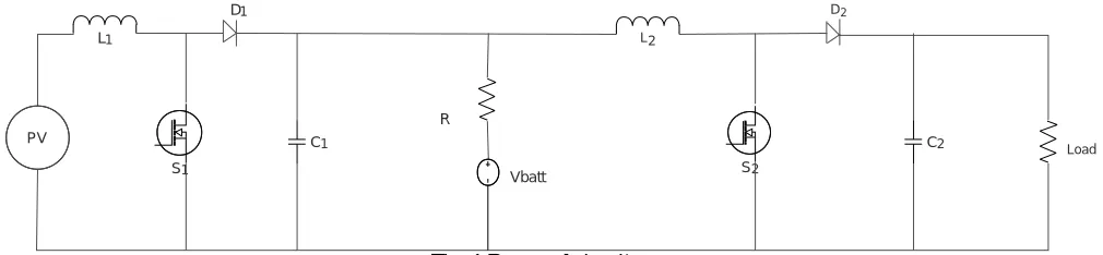
Fig. 1 Proposed circuit
C1 C2
L1 L2
PV
R
S2
S1
Vbatt
D1 D2
The proposed three port two boost converter is shown in the figure. It has two input inductors L1and L2. Inductor L1is
used to charge the battery or power the load. Or do both in certain modes. Inductor L2 is for powering the load. This
circuitry is able to realize the MPPT while regulating the load. Vbattis the battery voltage source, to be used either to
absorb or release power. The converter requires two diodes D1,D2 two capacitors C1, C2 and two mosfets S1,S2. The
first boost converter has a load R in series with battery.
III.WORKING
The proposed circuit is an integration of two basic boost converters. It has four modes of operation. MODE 1
This mode happens when PV power is large enough to supply the load, and has extra energy for the battery. In this mode the two boost converters are in operation.
MODE 2
This mode happens when PV power is not enough to sustain the load and it needs the storage device to supply the remaining power. In this mode also two boost converters are in operation.
MODE 3
This mode happens when PV power is just able to supply the load and the net current in the battery during this mode is zero. This means that the battery is not being charged or discharged.
MODE 4
In this mode PV is not able to produce energy. So the battery provides the input to the second boost converter. The first boost converter is not in operation.
OPERATION MODES POWER CONDITION(W)
Mode 1 PV to Battery and Load
Mode 2 PV array and Battery to the Load
Mode 3 PV array to the Load (Battery =0)
Mode 4 Battery to the Load (PV=0)
Table. 1 Operating modes
IV.CIRCUIT DESIGN
INDUCTOR DESIGN
To have smaller output ripple, both inductor L1 and L2 are designed to operate in continuous conduction mode (CCM).
However, if the load is too small, the current will naturally go into discontinuous conduction mode (DCM). The design point is at the boundary between the CCM and DCM. Where the output current is 50% of the rated value to spread the component stress evenly. The boost converter inductors is chosen as,
L1 , L2> d1(1-d1)²R/2f
CAPACITOR DESIGN
Maximum capacitance is required in the boost converter mode because output of boost converter is pulsating in nature. The Capacitor can be chosen as,
C1, C2>IodTS /ΔV
ΔV is the peak-peak voltage ripple of the output voltage and V is the output voltage. Values of C1 and C2 depend on the
load and battery voltage respectively.
V. SIMULATION
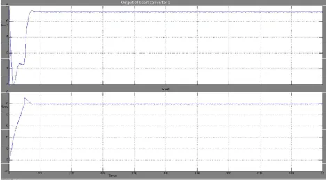
The Simulink model of proposed system is shown in figure 1. Here the converter is designed for an input of 12V. The output of first boost converter is designed for 24V. And the output of second boost converter is designed for 50V. The power output is considered to be 30W and frequency is taken as 20KHz. PI control is used for the proposed circuit.
Fig. 2 Simulink model of proposed circuit
The simulation result of the proposed system is shown in figure 2. It shows the output of first boost converter is 24 V and output of the proposed converter is 50 V. By using PI controller the peak overshoot is considerably reduced.
The gate pulses for on or off operation of active switches are shown in figure.
Fig. 4 Gate pulses of mosfet S1 and S2
V. HARDWARE IMPLEMENTATION
The hardware implementation of the proposed system is shown in fig 5. The circuit is implemented by using dsPIC30F2010. The voltage regulator used is LM7805 .
Fig. 5 hardware implementation of proposed system
Fig. 6 Output of the proposed converter
The output of the first boost converter of the proposed system is shown in figure 7. Here the output is designed for 24V.
Fig. 7 Output of the first boost converter
VI. RESULT
system are shown in fig 6 and 7. The output obtained for the first boost converteris 24V. And the output of proposed converter is 50V.
VII. CONCLUSION
This paper proposes a novel three port converter for a PV-Battery-Load system. The converter is derived from the integration of two boost converter. Experimental results are provided to confirm the converter operation in reference to DISO and SISO operations. Here the boost converters can either operate individually or simultaneously. The different modes ensure the load regulation, MPPT, and battery charging. The proposed circuit has only two switches and two diodes so switching losses and conduction losses are reduced.
REFERENCES
[1] A.Kavousi, N.Farokhnia, A.Vahabzadeh, M.Nazari and G.B. Gharehpetian, “Comparison betwwen Two Stand-alone PV configurations:Series PV s Versus Series VSCs. ” in pp.1-5 EPQU 2011-11.
[2] L.An and D.C Lu, “Design of a Single-Switch DC_DC Converter for a PV Battery-Powered Pump System with PFM+PWM Control,” IEEE Trans.Ind.Electronics.,vol.62 ,no.2, pp.910-921,Feb.2015.
[3] T>F Wu, C.H.Chang, L.C Lin and C.L Kuo, “Power loss Comparisson of Single- and Two-Stage Grid Connected Photovoltaic System, “IEEE.Trans.Energy Conversion,vol.26,no.2.707-715,June 2011.
[4] W.F. Hu, H.F. Wu, Y.Xing, K,Sun, “A Full-Bridge Three-port Converter for Renewable Energy Application, “ in Annual IEEE pp.57-62 APEC2014-29