R E S E A R C H
Open Access
Efficient bit rate control method for distributed
video coding system
Chang Woo Lee
Abstract
An efficient bit rate control method for the transform domain distributed video coding (DVC) system is proposed. In order to decide quantization levels of each transform coefficient in the proposed distributed video decoder, a new bitplanewise zigzag scanning method is used. The bit rate can be controlled precisely in the proposed system, since the number of available bit rates is equal to the number of bitplanes. On the other hand, the bit rate is controlled by changing fixed quantization tables in conventional methods. In the proposed DVC system, Wyner-Ziv frames can be efficiently reconstructed by refining the side information with transmitted parity bits. If there is no transmitted parity bit, the side information is not refined and it is considered to be a decoded Wyner-Ziv frame. The side information is refined more precisely, as the amount of transmitted parity bits increases. The proposed DVC system provides superior coding performance with a precise bit rate control compared to conventional methods.
Keywords:Distributed video coding, Side information, Wyner-Ziv frame, Efficient bit rate control, Bitplanewise zigzag scanning
Introduction
Efficient compression of video data is essential for storage and communication, since the amount of video data is very large. Video coding standards, such as MPEG or H.264, have been widely used to compress video data. The temporal and spatial correlations of video data are used by adopting the motion compen-sated prediction and discrete cosine transform (DCT) in the encoder of conventional video coding systems. The conventional video encoder is more complex than the decoder is, since motion compensated prediction requires many operations. This conventional video coding system is appropriate for systems, in which video data is encoded by one complex encoder and decoded by many simple decoders.
A new video coding technique termed distributed video coding (DVC) has been proposed [1-18]. It is based on the Slepian-Wolf and Wyner-Ziv theorems. The Slepian-Wolf theorem says that the minimum rate for encoding two correlated sources separately and decoding jointly is the same as the minimum rate for joint encoding [19]. Wyner and Ziv studied a particular
case of Slepian-Wolf coding corresponding to the lossy source coding [20]. In DVC systems, the complexity of encoders is greatly reduced by removing motion estima-tion operaestima-tions in the encoder, since the correlaestima-tion between frames is utilized in decoders [1]. The DVC sys-tem is appropriate for emerging applications, such as wireless low-power video surveillance systems, visual sensor networks and mobile systems with ultra light encoders [2,3]. The transform domain DVC coding sys-tem named Power-efficient, Robust, hIgh compression Syndrome based Multimedia coding (PRISM) has been proposed [4]. In this system, the low frequency coeffi-cients are compressed using a trellis-based syndrome Slepian-Wolf code, and the high frequency coefficients are entropy coded. While this system provides good cod-ing performance, the encodcod-ing complexity is high. The most popular DVC system was proposed by Aaron et al. at Stanford university [5]. In this system, the input frames in encoders are divided into key frames and Wyner-Ziv frames. While key frames are encoded using intra-frame coding techniques, such as H.264 intracod-ing technique, Wyner-Ziv frames are encoded with channel encoders such as turbo codes or LDPC codes, and only parity bits are transmitted for Wyner-Ziv frames. In the decoder, the side information, which is an Correspondence:[email protected]
School of Information, Communications and Electronics Engineering, The Catholic University of Korea, Bucheon-City, Kyunggi-Do, South Korea
estimate of the original Wyner-Ziv frame, is obtained using key frames. Motion compensated interpolation tech-niques are usually used to obtain side information. Wyner-Ziv frames can be decoded with the side informa-tion and transmitted parity bits, since the side informainforma-tion can be considered to be a noisy version of the original Wyner-Ziv frame. Wyner-Ziv frames in conventional dis-tributed video decoders are reconstructed in the dequanti-zation process, using the side information and transmitted parity bits. If the parity bits are not enough, Wyner-Ziv frames can’t be decoded successfully. On the contrary, sending too much parity bits results in bit rate overhead. Thus, the feedback channel is usually used, since the amount of parity bits is not known in the encoder. The transmission of parity bits is requested through the feed-back channel, until the errors are corrected to decode Wyner-Ziv frames. To eliminate the feedback channel, the amount of parity bits should be calculated in the encoder. Brites et al. proposed a simple side information generation technique and encoder rate control method by using the entropy and relative error probabilities [6]. However, the coding performance for the systems without feedback channels degrades due to the mismatch between the esti-mated and real bit rates [6-8]. Recently, a method for con-straining the number of feedback requests to a fixed maximum number ofNrequests was proposed [9].
In this paper, we propose an efficient bit rate control method for the transform domain DVC system. A new bitplanewise zigzag scanning method to decide quantization levels of each transform coefficient is pro-posed to maximize the rate distortion performance. The different bit rates in the proposed bitplanewise zigzag scanning method are obtained at each scan of the bit-planes. While the number of available bit rates in the conventional DVC systems is seven or eight, which is the number of fixed quantization tables, the quantization table can be easily generated at each scan in the pro-posed system. The bit rate can be controlled more pre-cisely in the proposed DVC system, since the number of available quantization tables is about eight times greater than that for conventional systems. In the proposed DVC system, the side information is refined with trans-mitted parity bits, in which the side information refined with transmitted parity bits is considered to be the decoded Wyner-Ziv frame. If no parity bit is transmitted, the side information is not refined and it becomes the reconstructed Wyner-Ziv frame. As the amount of parity bits increases, the quality of decoded Wyner-Ziv frames improves by refining the side information more precisely with parity bits. The proposed decoding method pro-vides superior performance to conventional methods, especially at low bit rates, since the side information can be refined with a small number of parity bits. Computer simulation results show that the proposed decoding and
bit rate control method provides superior coding per-formance and finer bit rate control than the conven-tional method. While convenconven-tional DVC systems usually focus on the performance improvement or management of feedback channel [5-17], the proposed DVC system deals with the precise bit rate control method and per-formance improvement.
In Distributed video coding system, the DVC system is explained. The proposed DVC system and proposed bit rate control method are presented in Proposed DVC sys-tem and Proposed bit rate control method, respectively. Performance is evaluated in Performance evaluation. Finally, Conclusions are given in Conclusion.
Distributed video coding system
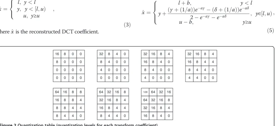
Figure 1 depicts the conventional transform domain DVC system [5,10,11]. The odd and even numbered frames in the encoder are divided into key frames and Wyner-Ziv frames, respectively. While the key frames are coded using an intraframe coding technique, Wyner-Ziv frames are coded using a channel encoder, such as turbo or LDPC encoders. Before being encoded, the Wyner-Ziv frames are transformed into the DCT domain to increase the coding efficiency. Each transform coefficient is quantized using the quantization table shown in Figure 2 [12]. The DC coefficients are quantized using a uniform quantizer with a step size, since the maximum value of DC coeffi-cients for 4 × 4 block is 1024.
SSDC¼1024=NQ DC; ð1Þ
whereSSDCis the step size for DC coefficients andNQ_DC is the number of quantization levels for DC coefficients. The same kind of quantizers for AC coefficients can be used to quantize AC coefficients. If MaxACn is the max-imum absolute value for thenth AC coefficient, the step size for thenth AC coefficient is given by
SSACn¼2MaxACn=NQ ACn; ð2Þ
Performance evaluation gives the performance analysis for each AC quantizer.
Transform coefficients are grouped into bitplanes from the most significant bit (MSB) to the least significant bit (LSB), after being quantized. Each bitplane is encoded using turbo codes and only parity bits are transmitted for Wyner-Ziv frames. Each bitplane of the transform coefficients in the decoder is reconstructed with side information and par-ity bits. The side information is usually obtained by motion compensated interpolation techniques using key frames. Then, Wyner-Ziv frames are decoded using a dequantiza-tion process with the reconstructed bitplanes. The follow-ing simple method can be used [13], if land u represent the lower and the upper bounds of the quantizer interval, respectively, to reconstruct the source information x in Wyner-Ziv frames using a side informationy.
^
x¼
l; y<l y; y<½ Þl;u
u; y≥u ;
8 < :
ð3Þ where^xis the reconstructed DCT coefficient.
The following optimal reconstruction method can be also used to minimize the mean squared error of the reconstructed value for each DCT coefficient [12,13]:
^
x¼Ex qj 0;y ¼
Z u
l xfxy
x yj Þdx
Z u
l fxy x
y dx; ð4Þ
where q' is the decoded quantization bin and E(·) is the expectation operator. In Eq. (4), the conditional probability density functionfx|y(·) represents residual sta-tistics between corresponding coefficients in Wyner-Ziv frames and side information; the Laplacian distribution is assumed [14,15]. The reconstructed DCT coefficient can be obtained using
^
x¼
lþb; y<l
yþðγþð1=αÞÞe
αγðδþð1=αÞÞeαδ
2eαγeαδ ; y∈½ Þl;u
ub; y≥u
; 8 > < > :
ð5Þ
Quantizer Turbo Encoder Buffer Turbo Decoder Reconstruction Motion-compensated Interpolation Intraframe Encoder Intraframe Decoder Wyner-Ziv Frames Decoded Wyner-Ziv Frames Key Frames Deocded Key Frames Request bits Side Information Encoder Decoder DCT IDCT DCT Parity bits Bit-planes 1~Mk Dequantization Using Side Information
and Decoded Bits
Figure 1Conventional DVC system.
32 8 4 0
8 4 0 0
4 0 0 0
0 0 0 0
64 16 8 8
16 8 8 4
8 8 4 4
8 4 4 0
128 64 32 16
64 32 16 8
32 16 8 4
16 8 4 0 16 8 0 0
8 0 0 0
0 0 0 0
0 0 0 0
32 16 8 4
16 8 4 0
8 4 0 0
4 0 0 0
32 16 8 4
16 8 4 4
8 4 4 0
4 4 0 0
64 32 16 8
32 16 8 4
16 8 4 4
8 4 4 0
withb¼α1þ Δ
1eαΔ; γ¼ylandδ¼uy:
In Eq. (5), α is the Laplacian distribution parameter for each DCT coefficient and Δ is the quantization bin size.
Proposed DVC system
Figure 4 depicts the DVC system proposed in this paper. In this system, Wyner-Ziv frames are decoded by refin-ing the side information with parity bits. If there is no parity bit, the side information is not refined and it is considered a decoded Wyner-Ziv frame. Thus, in the proposed system, the decoded Wyner-Ziv frame is equal to the side information at the zero bit rate. In this case, the bit rate means the amount of transmitted parity bits that are used to reconstruct Wyner-Ziv frames. As the amount of transmitted parity bits increases, the quality of Wyner-Ziv frames improves by refining the side infor-mation more precisely with the reconstructed bitplane. In the conventional DVC system, Wyner-Ziv frames are
decoded by dequantizing each transform coefficient of the Wyner-Ziv frame with side information and parity bits. Thus, if the quantization level for a transform coef-ficient is zero in the quantization table of Figure 2, it is decoded as zero in the conventional DVC system, while the side information is used as initial values for all trans-form coefficients in the proposed DVC system.
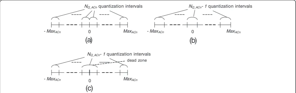
The side information is refined progressively, as the corresponding bitplanes are reconstructed using trans-mitted parity bits [18]. This improves the quality of the reconstructed Wyner-Ziv frame. If the optimal recon-struction method given in Eq. (5) is used, the side in-formation is refined more precisely. The AC quantizer with a dead zone, which is shown in Figure 3(c), is used to quantize AC coefficients, since the progressively re-finement process can be implemented with the quantizer. This exhibits better performance than the symmetric quantizer shown in Figure 3(a). The non-symmetric quantizer cannot be used for the progres-sively refinement process, since it is nonsymmetric with respect to the zero value.
0
NQ_ACnquantization intervals
MaxACn
- MaxACn 0
NQ_ACn- 1 quantization intervals
MaxACn
- MaxACn
0
NQ_ACn- 1 quantization intervals
MaxACn
- MaxACn
dead zone
(a)
(b)
(c)
Figure 3Quantizers for AC coefficients (a) Symmetric quantizer (b) Nonsymmetric quantizer (c) Quantizer with a dead zone.
Quantizer Turbo
Encoder
Turbo Decoder
Refiner
Motion-Compensated
Interpolation
Intraframe Encoder
Intraframe Decoder
Wyner-Ziv Frames
Decoded Wyner-Ziv Frames
Key Frames
Deocded Key Frames
Decoder
DCT
IDCT Encoder
DCT Parity
bits
Side Information
Buffer
Request bits
Refining Side Information Using Decoded Bits
The performance of the proposed decoder is superior to that of the conventional decoder, if the following in-equality holds.
X
M1
i¼0
X
N1
j¼0
uWynerZivð Þ i;j u^WynerProp:Zivð Þi;j
2
<MX1 i¼0
X
N1
j¼0
uWynerZivð Þ i;j u^ConvWyner:Zivð Þi;j
2
;
ð6Þ
where uWyner−Ziv(i,j), u^WynerZivProp:ð Þi;j and ^uWynerZiv Conv:ð Þi;j represent the pixels of the original Wyner-Ziv
frame, the reconstructed Wyner-Ziv frame in the proposed decoder and the reconstructed Wyner-Ziv frame in the conventional decoder, respectively. In the case where there is no parity bit for Wyner-Ziv frames,u^PrWynerop: Zivð Þi;j is the side information, while ^uConvWyner:Zivð Þi;j is zero. As the amount of parity bits increases, ^uWynerZivProp:ð Þi;j is refined more precisely, while u^WynerZivConv:ð Þi;j is recon-structed by the dequantization process. Although the performance of the proposed decoder depends on the quality of the side information, the proposed decoder outperforms the conventional decoder significantly, espe-cially at low bit rates. This is shown in Performance evaluation. The performance of the proposed decoder is much better than that of the conventional decoder, as
the side information gets closer to the original Wyner-Ziv frame.
Proposed bit rate control method
A new method to determine the quantization levels of each transform coefficient for a given bit rate is pro-posed for a precise bit rate control of DVC system, as follows. The following Lagrange multiplier can be used to find the optimum order to increase the quantization levels for each transform coefficient.
mini ΔDjð Þ þi λΔRjð Þi; i¼1;. . .;Mandj¼1;. . .;N; ð7Þ
whereMandNare the number of transform coefficients and the number of bitplanes, respectively. ΔDj(i) is the decreased distortion caused by increasing the quantization levels of ith transform coefficients on the jth bitplanes, and ΔRj(i) is the increased rate needed to increase the quantization level. The optimum scanning order can be obtained by searching the transform coeffi-cient i that minimizes the above formula for each bit-plane from 1 to N. However, the optimum scanning order differs for each video sequence. Thus, in the de-coder, the optimum scanning order cannot be obtained before the decoding process completes.
We propose the following scanning method to deter-mine the quantization levels of each transform
0 0.01 0.02 0.03 0.04 0.05 0.06
1 4 7 10 13 16 19 22 25 28 31 34 37 40 43 46 49 52 55 58 61
Average Bits
per Bitplane
Bitplane Number
DC AC1 AC2 AC3 AC4 AC5 AC6 AC7 AC8 AC9 AC10~ AC14
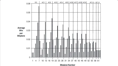
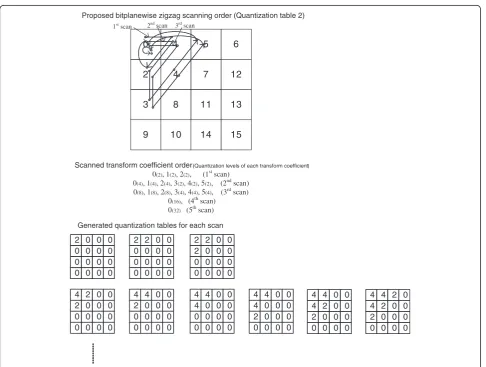
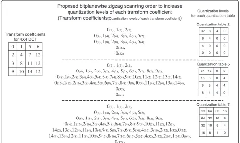
coefficient for a given bit rate. The amount of parity bits required for the least significant bit (LSB) of transform coefficients is greater than that for the most significant bit (MSB), since the probability that the side information is outside the quantization interval in decoding the LSB is higher than that in decoding the MSB. Figure 5 gives the average number of parity bits required to encode each bitplane for all video sequences used for perform-ance simulations in Performperform-ance evaluation, for which the seventh quantization table in Figure 2 is used. As can be seen, the average number of bits for LSB is much larger than that for MSB for each transform coefficient. Even if the other quantizers are selected, we can observe the same fact. By considering this phenomenon, the bit-planewise zigzag scanning method is proposed to in-crease the quantization level for each transform coefficient. Figure 6 and Figure 7 illustrate the new scan-ning method. Figure 6 illustrates the proposed zigzag scanning method for the second quantizer in detail. At each scan, the quantization level for each transform coefficients increases subsequently. In Figure 7, the
proposed scanning method for quantization table 2, 5 and 7 is described. As the bit rate increases, the quantization level for each transform coefficient increases progressively from low frequency components to maximize the rate dis-tortion performance. Different bit rates are obtained at each scan of bitplanes in the proposed bitplanewise zigzag scan-ning method. While the number of different rates depends on the number of quantization tables in the conventional methods, it is equal to the number of bitplanes in the pro-posed method. For example, the propro-posed DVC system provides 63 kinds of bit rates if the seventh quantizer table in Figure 2 is used for the proposed bitplanewise zigzag scanning, while the conventional DVC system only pro-vides seven kinds of bit rates, which is the same number as the quantization tables. For two LSB bitplanes of the sev-enth quantizer table in Figure 2, the quantization levels in-crease inversely from high frequency to low frequency coefficients, since the large number of quantization levels for the low frequency components reduce the correlation between the two LSB bitplanes of low frequency compo-nents and the side information. We can control bit rates
0 1 5 6
2 4 7 12
3 8 11 13
9 10 14 15
Scanned transform coefficient order(Quantization levels of each transform coefficient)
0(2), 1(2), 2(2), (1stscan) 0(4), 1(4), 2(4), 3(2), 4(2), 5(2), (2ndscan) 0(8), 1(8), 2(8), 3(4), 4(4), 5(4), (3rdscan)
0(16), (4thscan) 0(32) (5thscan)
Proposed bitplanewise zigzag scanning order (Quantization table 2)
1stscan 2ndscan 3rdscan
2 0 0 0 0 0 0 0 0 0 0 0 0 0 0 0
2 2 0 0 0 0 0 0 0 0 0 0 0 0 0 0
2 2 0 0 2 0 0 0 0 0 0 0 0 0 0 0
Generated quantization tables for each scan
4 2 0 0 2 0 0 0 0 0 0 0 0 0 0 0
4 4 0 0 2 0 0 0 0 0 0 0 0 0 0 0
4 4 0 0 4 0 0 0 0 0 0 0 0 0 0 0
4 4 0 0 4 0 0 0 2 0 0 0 0 0 0 0
4 4 0 0 4 2 0 0 2 0 0 0 0 0 0 0
4 4 2 0 4 2 0 0 2 0 0 0 0 0 0 0
precisely and get better coding results, as is shown in the simulations of the next Section, using the proposed scan-ning method.
Performance evaluation
We performed extensive computer simulations to evalu-ate the coding performance of the proposed DVC sys-tem. We used 150 frames of QCIF video sequences from Foreman, Stefan and Mobile video sequences, shown in
Figure 8. Foreman sequences are widely used as test sequences and Stefan sequences have high motion activ-ities, while Mobile sequences are complex. The same technique as that of the DISCOVER system [10,11] is used for simulations to obtain side information. The for-ward motion estimation, the bilateral motion compen-sated interpolation and the motion vector correction techniques using weighted median filters are used to generate the side information. The PSNR (peak signal to Proposed bitplanewise zigzag scanning order to increase
quantization levels of each transform coefficient
(Transform coefficients(Quantization levels of each transform coefficient))
0(2), 1(2), 2(2),
0(4), 1(4), 2(4), 3(2), 4(2), 5(2),
0(8), 1(8), 2(8), 3(4), 4(4), 5(4),
0(16),
0(32)
0(2), 1(2), 2(2),
0(4), 1(4), 2(4), 3(2), 4(2), 5(2), 6(2), 7(2), 8(2), 9(2),
0(8),1(8),2(8),3(4),4(4),5(4),6(4),7(4),8(4),9(4),10(2),11(2),12(2),13(2),14(2),
0(16),1(16),2(16),3(8),4(8),5(8),6(8),7(8),8(8),9(8),10(4),11(4),12(4),13(4),14(4),
0(32),
0(64)
0(2), 1(2), 2(2),
0(4), 1(4), 2(4), 3(2), 4(2), 5(2),
0(8), 1(8), 2(8), 3(4), 4(4), 5(4), 6(2), 7(2), 8(2), 9(2),
0(16),1(16),2(16),3(8),4(8),5(8),6(4),7(4),8(4),9(4),10(2),11(2),12(2),
14(2),13(2),12(4),11(4),10(4),9(8),8(8),7(8),6(8),5(16),4(16),3(16),2(32),1(32),0(32),
14(4),13(4),12(8),11(8),10(8),9(16),8(16),7(16),6(16),5(32),4(32),3(32),2(64),1(64),0(64),
0(128)
0 1 5 6
2 4 7 12
3 8 11 13
9 10 14 15
Transform coefficients for 4X4 DCT
32 8 4 0
8 4 0 0
4 0 0 0
0 0 0 0
64 16 8 8
16 8 8 4
8 8 4 4
8 4 4 0
128 64 32 16
64 32 16 8
32 16 8 4
16 8 4 0
Quantization levels for each quantization table
Quantization table 2
Quantization table 5
Quantization table 7
Figure 7Proposed bitplanewise zigzag scanning method to determine quantization levels of each transform coefficient (quantization table 2, 5, 7).
(a)
(b)
(c)
noise ratio) between the original and the decoded Wyner-Ziv frame is used as a performance measure.
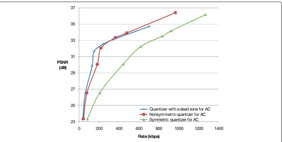
First, the performance for each AC quantizer in the conventional DVC system is evaluated using the opti-mal dequantization methods given in Eq. (5) and the conventional quantization tables in Figure 2. As is shown in Figure 9, the symmetric AC quantizer depicted in Figure 3(a) performs worst among the quantizers. The
bit rate increases significantly, since many parity bits are used for the AC coefficients near the zero value in the symmetric AC quantizer. The quantizer with a dead zone performs better than the nonsymmetric quantizer at low bit rates, while the nonsymmetric quantizer pro-vides slightly better performance than the quantizer with a dead zone at high bit rates. The quantizer with a dead zone in Figure 3(c) is used for the following
23 25 27 29 31 33 35 37
0 200 400 600 800 1000 1200 1400
PSNR (dB)
Rate (kbps)
Quantizer with a dead zone for AC Nonsymmetric quantizer for AC Symmetric quantizer for AC
Figure 9Comparison of coding performance for AC quantizers (using the optimal dequantization method).
30 30.5 31 31.5 32 32.5 33 33.5 34 34.5 35
0 100 200 300 400 500 600 700 800
PSNR (dB)
Rate (kbps)
Coefficient by coefficient scan
Optimal scan Proposed scan
simulations, since it performs well and the proposed decoding method, in which the side information is refined progressively, is easily implemented using the quantizer with a dead zone.
Next, the performance of the proposed bitplanewise zig-zag scanning method, which is used to determine quantization levels of each transform coefficient in the pro-posed DVC system, is compared with those of the optimal
23 25 27 29 31 33 35
0 100 200 300 400 500 600 700 800
PSNR (dB)
Rate (kbps)
Proposed (Optimal reconstruction, Q7) Proposed (Optimal reconstruction, Q5) Conventional (Optimal dequantizer)
Figure 11Comparison of coding performance between conventional and proposed DVC systems for Wyner-Ziv frames (Optimal reconstruction, Q7: Using the proposed bitplanewise zigzag scanning method with the maximum bit rate for the seventh quantizer table, Q5: Using the proposed bitplanewise zigzag scanning method with the maximum bit rate for the fifth quantizer table).
23 25 27 29 31 33 35
0 100 200 300 400 500 600 700 800
PSNR (dB)
Rate (kbps)
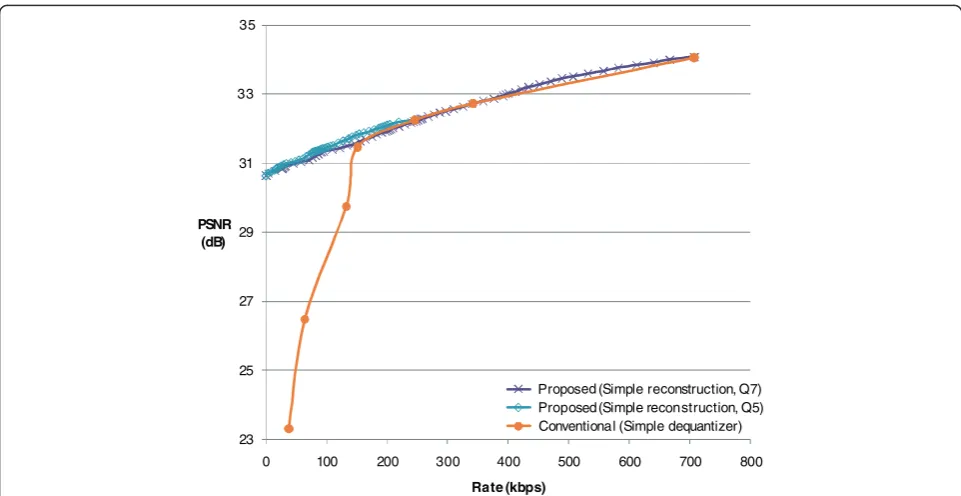
Proposed (Simple reconstruction, Q7) Proposed (Simple reconstruction, Q5) Conventional (Simple dequantizer)
scan and coefficient by coefficient scan. For the seventh quantization table in Figure 2, different quantization tables are generated for each scanning method. As is shown in Figure 10, the proposed scanning method exhibits better coding performance than the method in which the quantization level increases subsequently from low fre-quency components to high frefre-quency components. The rate represents the number of parity bits that are used to
reconstruct Wyner-Ziv frames. The optimum scan is obtained using a Lagrange multiplier given in Eq. (7) to maximize the rate distortion performance for the entire test sequences and it represents the upper bound of rate distortion. As can be seen, the proposed bitplanewise zig-zag scanning method provides close performance to that for the optimum scanning method and much better per-formance than the coefficient scanning method.
(a)
(b)
(c)
(d)
(e)
(f)
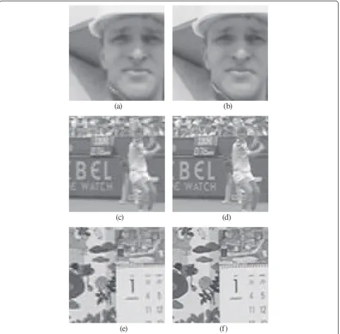
Figure 13Reconstructed images that are magnified for comparison. (a)Conventional DVC system (tenth frame of Foreman sequence at 0.066406 bit per pixel)(b)Proposed DVC system (tenth frame of Foreman sequence at 0.066406 bit per pixel)(c)Conventional DVC system (tenth frame of Stefan sequence at 0.156250 bit per pixel)(d)Proposed DVC system (tenth frame of Stefan sequence at 0.156250 bit per pixel)(e)
Then, the coding performance of the proposed DVC system is compared to that of the conventional DVC system in Figure 11 and Figure 12. Especially, at low bit rates, the coding performance of the proposed DVC sys-tem is significantly better than that of the conventional DVC system, since the side information can be refined with a small number of parity bits in the proposed DVC system. The side information is used as the initial value for all DCT coefficients in the proposed DVC system, while the side information is not used as the initial value for the DCT coefficients with zero quantization level in the conventional DVC system. As can be seen in Figure 7, the different bit rates can be assigned as the quantization tables are flexibly generated in the proposed scanning method, while seven fixed quantization tables are used in the conventional system. Thus, the proposed DVC sys-tem provides much finer bit rate control, as can be seen in Figure 11 and Figure 12. The performance for the op-timal reconstruction method given in Eq. (5) is superior to that of the simple reconstruction method, given in Eq. (3). Figure 13 compares the reconstructed images. As can be seen, the proposed DVC system provides better reconstructed images for all test video sequences.
The conventional DVC systems usually focus on the performance improvement [11-13,16,17] or management of feedback channel [6-9]. The proposed DVC system deals with the precise bit rate control method and per-formance improvement. The proposed system provides the efficient bit rate control method by using the bitpla-newise zigzag scanning method. While seven or eight fixed quantization tables are used in the conventional system, the number of available quantization tables in the proposed system is equal to the number of bitplanes. For example, for the seventh quantizer table in the con-ventional system, the number of available quantization tables in the proposed system is 63, which is the number of bitplanes. Thus, more quantization tables should be made in the proposed system. The increased decoder complexity for making more quantization tables is al-most negligible, since they can be easily generated using the bitplanewise zigzag scanning, which is shown in Figure 6 and Figure 7. The decoder complexity for refin-ing side information doesn’t increase compared to the conventional DVC systems, since the same dequantiza-tion method as the convendequantiza-tional DVC systems is used for refining. By setting the initial decoded Wyner-Ziv frame as the side information and refining the side infor-mation progressively, the proposed system shows better performance than the conventional DVC systems at low bit rates.
Conclusions
An efficient bit rate control method for the transform domain DVC system was proposed. By adopting the
bitplanewise zigzag scanning method to decide the quantization levels for each transform coefficient, the bit rate can be controlled more precisely in the proposed DVC system, since the number of available quantization tables is about eight times greater than that of fixed quantization tables, which is used to control bit rates in conventional DVC systems. Moreover, the proposed sys-tem provides superior coding performance by refining the side information using transmitted parity bits to re-construct Wyner-Ziv frames. The proposed system per-forms well especially at low bit rates, since the side information can be refined with a small number of parity bits. The side information is refined more precisely with transmitted parity bits. While Wyner-Ziv frames are decoded by dequantizing transform coefficients with side information and parity bits in the conventional DVC system, the Wyner-Ziv frames are reconstructed by re-fining side information with parity bits in the proposed system. Simulation results show that the proposed DVC system provides better performance than the conven-tional DVC system with precise bit rate control. Espe-cially, at low bit rates, the coding performance of the proposed DVC system is significantly better than the conventional DVC system and the proposed DVC sys-tem provides much better reconstructed images for all test video sequences than the conventional systems.
Competing interest
The authors declare that they have no competing interest.
Acknowledgement
This study was supported by the Basic Science Research Program through the National Research Foundation of Korea (NRF) funded by the Ministry of Education, Science and Technology (No. 2012–0002935).
Received: 10 May 2012 Accepted: 18 September 2012 Published: 22 November 2012
References
1. B Girod, AM Aaron, D Rebollo-Monedero, Distributed video coding. Proc. IEEE93(1), 71–83 (2005)
2. F Pereira,Distributed video coding: basics, main solutions and trends (International Conference on Multimedia and Expo, New York, NY, 2009), pp. 1592–1595
3. F Pereira, L Torres, C Guillemot, T Ebrahimi, R Leonardi, S Klomp, Distributed video coding: selecting the most promising application scenarios. Signal Process: Image Commun23(5), 339–352 (2008)
4. R Puri, A Majumdar, K Ramchandram, PRISM: a video coding paradigm with motion estimation at the decoder. IEEE Trans. Image Process.
16(10), 2436–2448 (2007)
5. A Aaron, S Rane, E Setton, B Girod,Transform-domain Wyner-Ziv codec for
video(SPIE Visual Communications and Image Processing, San Jose, CA,
2004), pp. 520–528
6. C Brites, F Pereira,Encoder rate control for transform domain Wyner-Ziv video
coding(IEEE International Conference on Image Processing, San Antonio, TX,
2007), pp. II.5–II.8
7. C Fu, J Kim,Encoder rate control for block-based distributed video coding(IEEE International Workshop MMSP, Saint Malo, 2010), pp. 333–338
9. J Skorupa, JN Deligiannis, P Lambert, A Munteanu, R Van de Walle, Distributed video coding with feedback channel constraints. IEEE Trans Circuits and Systems for Video Technology22(7), 1014–1026 (2012) 10. X Artigas, J Ascenso, M Dalai, S Klomp, D Kubasov, M Ouaret,The DISCOVER
codec: architectures, techniques and evaluation(Picture Coding Symposium,
Lisbon, Portugal, 2007), pp. 1–4
11. C Brites, J Ascenso, F Pereira, Improving transform domain Wyner-Ziv video coding performance. IEEE Int. Conference on Acoust. Speech Signal Process, II.525–II.528 (2006). Toulouse
12. C Brites, J Ascenso, JQ Pedro, F Pereira, Evaluating a feedback channel based transform domain Wyner-Ziv video codec. Signal Process: Image Commun23(4), 269–297 (2008)
13. D Kubasov, J Nayak, C Guillemot, Optimal reconstruction in Wyner-Ziv video coding with multiple side information. IEEE Int. Workshop on Multimedia Signal Process.183, 183–186 (2007). Crete
14. C Brites, F Pereira, Correlation noise modeling for efficient pixel and transform domain Wyner-Ziv video coding. IEEE Trans Circuits and Systems for Video Technology18(9), 1177–1190 (2008)
15. X Fan, O Au, NM Cheung, Transform-domain adaptive correlation estimation (TRACE) for Wyner-Ziv video coding. IEEE Trans Circuits and Systems for Video Technology20(11), 1423–1436 (2010)
16. R Martins, C Brites, J Ascenso, F Pereira, Refining side information for improved transform domain Wyner-Ziv video coding. IEEE Trans Circuits and Systems for Video Technology19(9), 1327–1341 (2009)
17. S Ye, M Ouaret, F Dufaux, T Ebrahimi, Improved side information generation with iterative decoding and frame interpolation for distributed video coding. IEEE International Conference on Image Processing, 2228–2231 (2008). San Diego, CA
18. CW Lee, Efficient decoding method for Wyner-Ziv video codec. Workshop of Image Processing and Image Understanding, 368–371 (2011). Jeju, Korea 19. D Slepian, J Wolf, Noiseless coding of correlated information sources. IEEE
Trans. Inf. Theory19(4), 471–480 (1973)
20. A Wyner, J Ziv, The rate-distortion function for source coding with side information at the decoder. IEEE Trans. Inf. Theory22(1), 1–10 (1976)
doi:10.1186/1687-6180-2012-244
Cite this article as:Lee:Efficient bit rate control method for distributed video coding system.EURASIP Journal on Advances in Signal Processing 20122012:244.
Submit your manuscript to a
journal and benefi t from:
7Convenient online submission
7Rigorous peer review
7Immediate publication on acceptance
7Open access: articles freely available online
7High visibility within the fi eld
7Retaining the copyright to your article