Modelling and Simulation of An Isolated
Power Generating System Using Doubly Fed
Induction Generators
Abhishek Satwase
1, G.S.R.Sanjeevini
2Assistant Professor, Department of Electrical Engineering, Mewar University, Chittorgarh, Rajasthan, India1
Assistant Professor, Department of Electrical Engineering, GVP College of Engineering for women, Visakhapatnam,
Andhra Pradesh, India2
ABSTRACT: There are many load centres that are isolated from the main utility grid. Some of them are remote villages, islands, ships, etc. They require isolated electric supply by means of stand-alone electrical generators to provide for their local electrical loads. The proposed model is used for standalone system where the power is fed directly to the local loads for the applications where the connectivity to the grid is not possible. The system can also be made to work in combination with grid and local loads .In Islanding mode the generator supplies the local loads during the light load and during heavy load condition, the excess power is absorbed/ supplied by battery energy storage system (BESS) which is connected parallel to dc link capacitor. A three phase load, independent wind energy conversion system is employed using DFIG operated at variable speeds for supplying the power to local loads and also perform the function of load levelling and harmonic elimination.
KEYWORDS: Doubly Fed Induction Generator, Wind Energy Conversion System, Battery Energy Storage System, Stator voltage, MPT, Parallel operation.
I. INTRODUCTION
In simple terms, a stand-alone generator refers to an isolated grid feeding a local load [2]. In the case of grid-connected variable-speed wind turbines, the total active power can be fed to the grid. For stand-alone systems that supply local loads, if the extracted wind power is more than the local load demand (including losses), the excess power from the wind turbine needs to be diverted to dump load or can be stored in a battery bank. Likewise, when the power extracted is less than the load at the consumer end, the remaining power needs to be supplied from a storage element like a flywheel, a super capacitor, compressed air, hydrogen storage, a secondary battery, etc. [3].
ISSN(Online) : 2319 - 8753
ISSN (Print) : 2347 - 6710
I
nternational
J
ournal of
I
nnovative
R
esearch in
S
cience,
E
ngineering and
T
echnology
(An ISO 3297: 2007 Certified Organization) Vol. 4, Issue 4, April 2015
squirrel cage asynchronous generators (SCIG) that operate at almost constant speeds, maximum power tracking (MPT) could not be accomplished.
II. SYSTEMDESCRIPTION
A simplified diagram of the proposed isolated wind energy conversion system (WECS) operating in parallel with two DFIG's that employ three voltage source converters that are IGBT based and operate on the principle of pulse width modulation (PWM) is shown in the fig 3.The DFIG's have two converters on the rotor side, which are useful for maximum power tracking (MPT) which can be achieved by controlling rotor speed. At the stator end of the DFIG, we have the stator side converter and there is a common dc bus battery bank along with the rotor side converter. Between the stator end and the stator side converter, a transformer (star-delta) is connected for eliminating harmonics and optimising the dc bus voltage. For the single phase load operation, a neutral point is provided on the star (Y) side of the transformer.
In order to achieve quick dynamic response, controlling of the converters is done by the stator flux oriented control by dissociating the q (active) and d (reactive) components of total stator currents and rotor currents of both the DFIG's. The total stator current means the addition of stator currents of both the DFIG's.
The task of the battery energy storage system, in short (BESS) is load levelling which is needed in the case of variable loads and uncertain wind speeds. As already mentioned, this BESS is provided at the dc bus of the converters. The location of the BESS proves to be advantageous in the sense that for the power transfer process to or from the battery, no extra converter is needed. The battery also helps in keeping the dc bus voltage constant at the time of load disturbances or load fluctuations. In order to remove ripples from the current from the battery, an inductive filter is connected in series with it.
For the designed wind energy conversion system (WECS), the new algorithm would be able to perform many functions like load levelling, harmonic elimination, MPT, and most importantly control of voltage and frequency at the stator end.
The control of the three converters results in achieving all the above mentioned characteristics that are important for any standalone operation. [2].For the stator side converter, an indirect current control scheme is applied. As the control operation is based on switching, that needs control signals for converter operation. For the stator side converter , these signals are produced by the reference stator currents' and total actual stator currents' error i.e. ( 𝐼𝑆,𝑡𝑜𝑡𝑎𝑙~𝐼𝑠,𝑟𝑒𝑓 ) and not by errors from the stator side currents .Thus, the stator side converter's switching is controlled, making the current of both the DFIG's balanced and sinusoidal at the nominal frequency. At the same time, harmonics and unbalance in the load side currents are taken care of by the transformer (star -delta) and the stator side converter. Also, only the total stator currents is needed and not individual stator currents of the DFIG's thus lessening the number of current sensors of stator side converter control.
This wind energy conversion system operates in three ways. Firstly, when the wind speed (𝑉𝑤) is high or /and the load demand (𝑃𝐿) is less, then the total active power produced by the wind energy conversion system (WECS) is more than that of the consumer load. The surplus power is redirected to the battery via the stator side converter. In the second case when the speed of the wind (𝑉𝑤) is low or/and load required is high and the generated total power of this WECS is less than that required at the consumer end, the remaining power is now provided by the dc battery bank via the stator side converter. In the third case, when the power generated is same as that consumed, then no power transfer takes place at the battery bank.
III.MATLAB BASEDMODELLING
Figure 3. Simulink model developed using SPS
IV.SIMULATIONRESULTS
The performance of the proposed WECS under different load conditions is demonstrated, simulated and discussed below. Functioning of the wind turbine-cum-battery energy storage system for steady state and dynamic wind speed is separately discussed. As mentioned earlier, under steady state condition, there are three modes of operation of a wind turbine i.e. synchronous mode, sub synchronous mode and super synchronous mode. For all the three modes of operation simulation is done and the obtained result is shown separately. For all the above mentioned cases graphs of load voltage (VL ), load current (IL), active power consumed at the load (P), reactive power required at load side (Q),
energy status of the battery (Vdc in p.u.) and the battery current (Idc) is plotted with respect to time.
ISSN(Online) : 2319 - 8753
ISSN (Print) : 2347 - 6710
I
nternational
J
ournal of
I
nnovative
R
esearch in
S
cience,
E
ngineering and
T
echnology
(An ISO 3297: 2007 Certified Organization) Vol. 4, Issue 4, April 2015
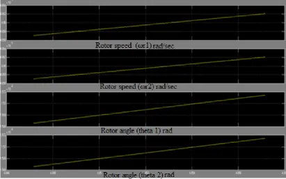
As soon as wind starts blowing the blades of turbine start rotating and when the wind speed achieves a minimum level of 6m/s energy is being generated by the turbine. The system is designed to track maximum power condition always, called Maximum Power Tracking (MPT) capability of the WECS. During the transient period when the turbines and DFIGs are accelerating, the battery charging current reduces. After a few cycles, the currents settle to the steady-state values. Each of the wind turbines is able to maintain its maximum coefficient of performance of 0.4412 irrespective of the wind speed, and the speeds of DFIGs settle to the speeds corresponding to MPT in a few cycles. Thus, WECS is able to deliver power at constant voltage and frequency irrespective of the wind speed and extracts power from the wind corresponding to MPT point. The transient condition can be discussed later. The movement of rotor and the position of rotor with respect to static position is also simulated and plotted with respect to time.
Figure 4.1 Rotor Speed and Rotor angle of the two DFIGs
Synchronous Mode of Operation
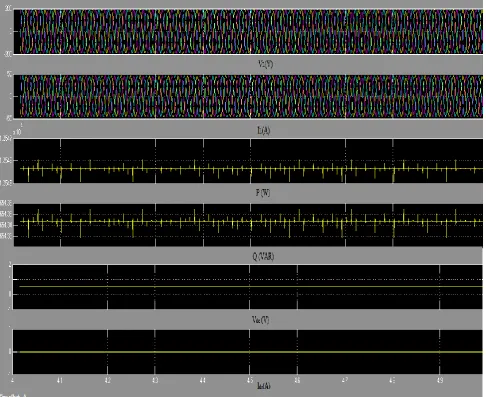
A wind turbine is said to be operated in the synchronous mode when the speed of wind is nearly same as the speed required for Maximum Power Tracking (MPT). In this case power generated by the Isolated Wind Energy Conversion System (WECS) is approximately same as the power required at the load end.
For Balanced Load
As assumed above, for synchronous mode of operation, the wind speed is assumed constant i.e. 8m/s and the total power (active and reactive both) is divided equally among the three phases. It is clearly seen from the simulation result obtained, the load voltage, VL and load current IL are constant as well as active and reactive power required. Since the
Figure 4.2 Simulation results of WECS for synchronous mode under balanced load condition (at wind speed 8m/s)
Super Synchronous Mode of Operation
ISSN(Online) : 2319 - 8753
ISSN (Print) : 2347 - 6710
I
nternational
J
ournal of
I
nnovative
R
esearch in
S
cience,
E
ngineering and
T
echnology
(An ISO 3297: 2007 Certified Organization) Vol. 4, Issue 4, April 2015
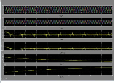
Figure 4.3 Simulation results of WECS for super synchronous mode under balanced load condition (at wind speed 10m/s)
Since the power generated in this case is more than the power required at the load end, extra power is diverted to the BESS. It is clearly seen from the simulation result Vdc and Idc. The battery is charged from its initial assumed value of
0.5pu.
Sub Synchronous Mode of Operation
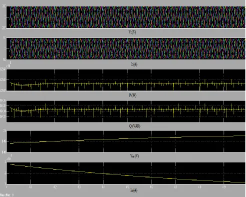
Figure 4.4 Simulation results of WECS for sub synchronous mode under balanced load condition (at wind speed 6m/s)
Since the power generated in this case is less than the power required at the load end, extra power needed to maintain the frequency and voltage of the system in balanced condition is taken from the BESS. It is clearly seen from the simulation result Vdc and Idc. The battery is dischargedfrom its initial assumed value of 0.5pu.
V. CONCLUSION
ISSN(Online) : 2319 - 8753
ISSN (Print) : 2347 - 6710
I
nternational
J
ournal of
I
nnovative
R
esearch in
S
cience,
E
ngineering and
T
echnology
(An ISO 3297: 2007 Certified Organization) Vol. 4, Issue 4, April 2015
REFERENCES
[1] G. Martin, “Renewable energy gets the „green‟ light in Chicago,” IEEE Power Energy Mag., vol. 1, no. 6, pp. 34–39, Nov./Dec. 2003.
[2] A. K. Jain and V. T. Ranganathan, “Wound rotor induction generator with sensorless control and integrated active filter for feeding
nonlinear loads in a stand-alone grid,” IEEE Trans. Ind. Electron., vol. 55, no. 1, pp. 218–228, 2008.
[3] K. Stunz and J. Nedrud, “Multilevel energy storage for intermittent wind power conversion: Computer system analogies,” in Proc. IEEE
Power Eng. Soc. Gen. Meeting, Jun. 2005, pp. 1950–1951.
[4] R. Cardenas, R. Pena, G. Tobar, R. Blasco-Gimenezs, P. Wheeler, G. Asher, and J. Clare, “Analytical and experimental evaluation of a wecs
based on a doubly fed induction generator fed by a matrix converter,” Proc. IEEE Int. Symp. Ind. Electron. IESE, Jun./Jul. 2008, pp. 2438–
2443.
[5] M. S. Khan and M. R. Iravani, “Hybrid control of a grid-interactive wind energy conversion system,” IEEE Trans. Energy Convers., vol. 23,
no. 3, pp. 895–902, Sep. 2008.
[6] B. C. Pal and F. Mei, “Modelling adequacy of the doubly fed induction generator for small-signal stability studies in power systems,” IET
Renewable Power Gener., vol. 2, no. 3, pp. 181–190, Sep. 2008.
[7] L. Xu, “Enhanced control and operation of DFIG-based wind farms during network unbalance,” IEEE Trans. Energy Convers., vol. 23, no. 4,
pp. 1073–1081, Dec. 2008.
[8] R. Pena, J. C. Clare, and G. M. Asher, “A doubly fed induction generator using back-to-back PWM converters supplying an isolated load
from a variable speed wind turbine,” Proc. Inst. Elect. Eng.—Elect. Power Appl., vol. 143, no. 5, pp. 380–387, Sep. 1996.
[9]
[10] R. Pena, R. Cardenas, J. Proboste, J. C. Clare, and G. M. Asher, “Sensorless control of a doubly-fed induction generator for standalone
operation,” in Proc. IEEE Power Electron. Spec. Conf., Jun. 2004, vol. 5, pp. 3378–3383.
[11] R. Pena, R. Cardenas, J. Proboste, J. Clare, and G. Asher, “Wind-diesel generation using doubly fed induction machines,” IEEE Trans. Energy Convers., vol. 23, no. 1, pp. 202–213, Mar. 2008.
[12] R. Cardenas, R. Pena, M. Perez, J. Clare, G. Asher, and F. Vargas, “Vector control of front-end converters for variable-speed wind-diesel
systems,” IEEE Trans. Ind. Electron., vol. 53, no. 4, pp. 1127–1136, Jun. 2006.
[13] L. A. C. Lopes and R. G. Almeida, “Wind-driven induction generator with voltage and frequency regulated by a reduced rating voltage
source inverter,” IEEE Trans. Energy Convers., vol. 21, no. 2, pp. 297–304, Jun. 2006.
[14] B. Singh, G. Kasal, A. Chandra, and Kamal-Al-Haddad, “Battery based voltage and frequency controller for parallel operated isolated
asynchronous generators,” Proc. IEEE Int. Symp. Ind. Electron.. Jun. 2007, pp. 883–888.
[15] B. Singh and G. K. Kasal, “Voltage and frequency controller for a three-phase four-wire autonomous wind energy conversion system,”
IEEE Trans. Energy Convers., vol. 23, no. 2, pp. 509–518, Jun. 2008.
[16] Sondes Skander-Mustapha , Ilhem Slama-Belkhodja , "Supervisory for parallel operation of two DFIG based wind farm using variable wind
speeds" 978-1-4577-0411-6/11, IEEE 8th International Multi-Conference on Systems, Signals & Devices, 2011.
[17] J. G. Slootweg, S. W. H. Haan, H. Polinder, and W. L. Kling, “General model for representing variable speed wind turbines in power system
dynamics simulations,” IEEE Trans. Power Systems, vol. 18, no. 1, pp. 144–151, Feb. 2003.
[18] Z. M. Salameh, M. A. Casacca, and W. A. Lynch, “A mathematical model for lead-acid batteries,” IEEE Trans. Energy Convers., vol. 7, no.
1, pp. 93–98, Mar. 1992.
[19] Puneet K. Goel , Bhim Singh, " Isolated Wind–Hydro Hybrid System Using Cage Generators and Battery Storage" IEEE transactions on
industrial electronics, vol. 58, no. 4, pp. 1141-1153, April 2011.
[20] B. Singh, S. S. Murthy, and S. Gupta, “Analysis and design of STATCOM based voltage regulator for self-excited induction generators,”
IEEE Trans. Energy Convers., vol. 19, no. 4, pp. 783–790, Dec. 2004.
[21] M. Kesraoui, N. Korichi, A. Belkadi, "Maximum power point tracker of wind energy conversion system", Renewable Energy 36 (2011) 2655-2662, Elsevier Ltd.
[22] P. Vas, Vector Control of AC Machines, New York: Oxford Univ. Press, 1990, ch. 2.
[23] Wikipedia
[24] T. Ackermann, “Wind power in power systems,” John Wiley and sons, England, 2005.
[25] www.mathworks.com/products/simulink
[26] http://www.cwet.tn.nic.in
[27] www.dieselserviceandsupply.com
[28] M. N. Zaggout, P. J. Tavner L. Ran" Wind Turbine Doubly Fed Induction Generator Fault Detection Based on Control Loop Signals," EWEA, Copenhagen 2012.
[29] Wenping Cao, Xiaoyan Huang, Ian French, Bin Lu "Simulation of a Site-Specific Doubly-Fed Induction Generator (DFIG) for Wind
Turbine Applications," IEEE, 978-1-4244-1736-0/08 ©2008.
[30] Anca D. Hansen, Lars H. Hansen "Market penetration of wind turbine concepts over the years".
[31] G.M. Joselin Herbert, S. Iniyan, Ranko Goic "Performance, reliability and failure analysis of wind farm in a developing Count ry" Renewable Energy, 35 (2010) 2739e2751 2010 Elsevier Ltd.
[32] Agam Kumar Tyagi, "Matlab and Simulink for engineers" ISBN 0-19-807244-9, Oxford University press 2012.
[33] WWEA half year report 2012.
[34] Rakhi Soni*, Monika Jain, Deepika masand," Islanding Operation of Dfig Based Battery Energy Storage System fo r Three Phase Load," International Journal of ChemTech Research CODEN (USA): IJCRGG ISSN: 0974-4290 Vol.5, No.2, pp 972-979, April-June 2013. [35] A GWEC annual market update2010, 2nd_edition, April_2011.