Design and Analysis of Circular Patch
Micro-Strip UWB Antenna for Breast cancer
Detection
Heena Choudhary
1, Romika Choudhary
2,Ashish Vats
3M. Tech Scholar, Dept. of Electronics & Communication Engineering, Swami Vivekananda Subharti University, Meerut, India1
Assistant Professor, Dept. of Electronics &Communication Engineering, Faculty of Engineering & Technology, Manav Rachna International University, Faridabad, India2,3
ABSTRACT:This research presents a novel Omni-directional micro-strip UWB antenna with enhanced bandwidth design to be used in breast cancer detection. The antenna consists of a circular radiating patch fed by inset feeding technique. Certain miniaturization techniques such as partial ground plane for expansion of bandwidth in order to achieve our intention. Details of antenna design and simulation results such as return loss and radiation patterns are discussed in this paper. The final antenna structure exhibits good UWB characteristics and has surpassed the bandwidth requirements. Proposed antenna has the advantages of wide bandwidth, compact size and low cost, good Omni-directional radiation patterns for using in microwave imaging applications. The maximum measured gain for the fabricated antenna is around6.1 dBi with an average efficiency above 88% throughout the bandwidth.
KEYWORDS:Ultra Wide Band (UWB), microwave imaging system, Miniaturization, Microstrip Antenna, Breast Cancer Detection
I. INTRODUCTION
Breast cancer is the most common non-skin related malignancy and the second leading cause of cancer death among women in the world [1]. It is the most common malignancy in women after skin cancer and the second leading cause of female cancer mortality [2]. Early detection of cancer is an important aspect for effective treatment. Widely used detection techniques include X-ray mammography, magnetic resonance imaging (MRI), and ultrasound technique [3]. Microwave imaging provides an alternative detection technique that requires simple configuration. The objective is to detect the variations in the dielectric properties of a tumour from the surrounding healthy tissue [4].The dielectric properties of human body tissue at microwave frequencies are sensitive to physiological factors of clinical interest, including water content, temperature, and vascularization. The dielectric properties of healthy and cancerous tissues at microwave frequencies revealed thatdielectric constant and conductivity for cancerous tissue are three or four times greater than that ofnormal tissue[5].For a long time, microwave engineers have dreamed of using nonionizing electromagnetic waves to image the human body in order to detect cancers. The breast can easily be accessed from outside, while internal organs are much less accessible. Normal breast tissue is also more translucent to microwaves than many other tissues, such as muscle or brain.The limitations of X-ray mammography provide clear motivation for the development of a complementary breast-imaging tool to assist in detection and diagnosis. According to the IOM report, an ideal breast screening tool:
-has low health risk
-issensitivetotumoursandspecificto malignancies -detects breast cancer at a curable stage
- is cost effective and widely available
For reliable detection of small malignant tumours, a significant and consistent contrast between malignant and other breast tissues is required.
II. RELATED WORK
Dielectric properties of biological tissues at radio and microwave frequencies have been the subject of research by many groups and comprehensive surveys have been publishedand could be used as a base to evaluate the behaviour of microwaves in human’s tissue. In the next decade, microwave systems are likely to become a viable diagnostic option for many women. Active microwave imaging (MWI) of the human body involves transmitting low-power, non-ionizing narrowband or wideband microwave signals into the area of interest using anantenna system, which in turn measures the scattered microwave signals. For this purpose, two active types of microwave imaging techniques - tomography and radar based are beingused to measure the scattered microwave signals.
Microwave tomography is based on diffraction based imaging. The dielectric properties are reconstructed back from the measurements based on the signals transmitted through UWB antennas into the human body. Reconstruction of images is based on iterative model procedures which are computationally extensive, as they always try to minimize the errors between measured and calculated electric fields.
Radar based approach tries to identify the difference in the permittivity due to scattering of small objects such as tumours. The scattered signals are processed to generate a map of backscattered microwave energy based on simple sum and delay algorithm approach. This technique offers good resolution, uses non-ionizing radiation and is relatively low cost and more comfortable, in comparison with the traditional X-ray mammography [6].
Microwave tomography and radar based microwave imaging techniques have been investigated in cancer detection [7-9]. UWB antennas used in medical imaging should be planar, compact, with high radiation efficiency and stability over the entire operation band. Most of UWB antennas presented in theliterature exhibit Omni-directional radiation patterns with low gain. Several kinds of antennas can be used, for instance, micro-strip, Vivaldi, Bowtie and circular patch antennas. [10-15].
Basic Breast Structure: The female breast has three major breast structures:
-Adipose tissue -Glandular tissue and -Connective tissue
The dielectric properties of breast tissue are primarily determined by the adipose content.For the purposes of microwave imaging; biological tissues can be classified as high content and low content, High water-content tissue consists of approximately 60-80% of water, including muscle and skin. Low water-water-content tissue includes bone and adipose tissue consisting of approximately 40% and 10% water respectively The normal breast largely consists of adipose tissue, and the presence of infiltrating neoplastic tissues of high water content will certainly lead to pronounced changes in the dielectric properties of breast tissue A good understanding of the dielectric properties of malignant and healthy tissues is important for the development of diagnostic and therapeutic technologies that utilize the microwave frequency range. It have been shown that dielectric properties of malignant tissues differ from normal tissues by varying amounts due to variations in water content between normal and malignant tissues. Generally malignant tumours develop an extensive network of blood vessels to aid their growth, resulting in increased water content in the region of the malignant tumour. Dielectric property is modelled by using Debye dispersion [16]-[17], and can be obtained normal breast (fatty) and tumour dielectric property that shown in Table I at 6 GHz [17&18].
Table1. Dielectric Property & Conductivity of Breast &Tumour Model at 6GHz
Normal Breast Tissue Breast Skin Tumour
r 9.5 35.7. 50
0.4 3.17 4
discusses the simulated and the experimental results performed and Section IV is summarized the final conclusions of this study.
III. ANTENNADESIGN
a. Antenna geometry
Figure 1 show the top and bottom view of the proposed antenna with partial ground plane.
(a) (b)
Figure 1 Geometry of proposed antenna (a) Top-View (b) Bottom View
The proposed antenna consists of a circular radiating patch and a ground plane fed by inset feeding technique for perfect impedance matching. The patch is connected to a micro-strip feed-line with the width of Wf and length of Lf. In the micro-strip feed line, the impedance of the micro-strip line is given by
[19]-𝑍𝑐 = 120
𝑟𝑒𝑓𝑓
1
𝑊𝑓
ℎ +1.393+0.667 𝑙𝑛
𝑊𝑓
ℎ +1.444
(1)
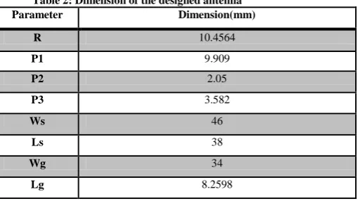
The antenna is realized on FR-4 substrate with dielectric permittivity εr = 4.4 and thickness h = 0.5 mm. Its width and
length denoted by W and L are respectively 46 mm and 38 mm. The origin of the coordinate system is taken at the centre of the structure. The geometrical parameters of the proposed antenna structure are tabulated in Table2.
Table 2: Dimension of the designed antenna
Parameter Dimension(mm)
R 10.4564
P1 9.909
P2 2.05
P3 3.582
Ws 46
Ls 38
Wg 34
The analysis of the proposed antenna structure is based on transmission line modal analysis.
DESIGNING EQUATIONS
(1) Resonant frequency for the TMmn0 modes can be written as-
𝑓𝑟 𝑚𝑛0 = 1
2
𝑋′𝑚𝑛 0
𝑎 [2]
𝑓𝑟 𝑚𝑛0 =1.8412 𝑣𝑜2𝑎𝑒
𝑟 [3]
(2) Effective Radius
𝑎𝑒 = 𝑎 1 + 2ℎ 𝑟 𝑎 𝑙𝑛
𝑎
2ℎ + 1.7726 1/2
[4]
(3) Radius of circular patch
𝑎 = 𝐹
1+2ℎ
𝑟 𝐹 𝑙𝑛
𝐹
2ℎ +1.7726
−1/2 [5]
𝐹 = 8.791×10⁹
𝑓𝑟 𝑟 [6]
(4) Effective dielectric constant is given by- 𝑒𝑓𝑓 = 𝑟+1
2 +
𝑟−1
2 1 + 12 ℎ 𝑎
−1/2
[7]
Where,
h = substrate thickness a = radius of circular patch
a eff = effective radius of circular patch
vo = speed of light
fr = resonant frequency
r = relative permittivity
eff = effective permittivity
(a) (b)
(c) (d)
Fig.2 the step by step development of the proposed antenna structure used for simulation
III. SIMULATION RESULTS AND DISCUSSION
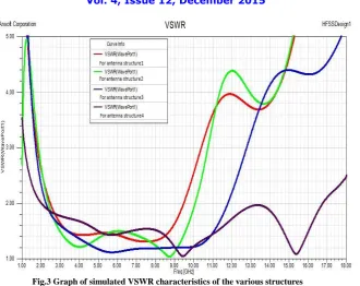
Fig.3 Graph of simulated VSWR characteristics of the various structures Structure 1: Antenna structure without any slot in ground plane Structure 2: With rectangular pair slot
Structure 3: With rectangular pair slot added with another slot between pair slot
Structure 4: With L shaped pair slot in addition with rectangular slot between them (Proposed antenna structure
From the plot of simulated VSWR Vs. frequency of proposed antenna structure, it is seen that the antenna has a bandwidth ranging from 2.01 to 16.78GHz for VSWR <2 dB, which is very attractive for UWB microwave imaging application. It is clearly seen from the graph and table 3 that addition of slots in ground plane improves impedance matching and there is a considerable amount of enhancement in bandwidth.
Table 3: Bandwidth covered for various antenna structures
Antenna Structure Bandwidth(MHz)
Structure 1 6990
Structure 2 7690
Structure 3 9530
Structure 4 14770
Fig.4 Group Delay vs. Frequency plot
From the figure, group delay variations of up to 0.3 ns can be observed within the operating bandwidth.Simulation results indicate that the antenna has the potential to detect breast tumours.
Radiation efficiency of the proposed antenna is shown in Figure 5. As can be seen from the below given figure, the radiation efficiency of the propose antenna is greater than 86% across the operation band. Simulation results shows that the antenna operates in the desired frequency bands with suitable radiation efficiency.
Fig.5. Radiation Efficiency of proposed antenna structure
The far field radiation pattern of the final structure is also simulated by HFSS which is illustrated by Fig. 6 for the frequency 8.4GHz.It can be seen that the patterns in the H-plane are Omni-directional as expected, whereas in the E
-2.00
4.00
6.00
8.00
10.00
12.00
14.00
16.00
18.00
Freq [GHz]
-0.20
0.00
0.20
0.40
0.60
0.80
1.00
G r o u p D e la y (W a v e Po r t1 ,W a v e Po r t1 ) [n ]Ansoft Corporation Group Delay Plot HFSSDesign1
Curve Info
GroupDelay(WavePort1,WavePort1) Setup1 : Sw eep1
2.00 4.00 6.00 8.00 10.00 12.00 14.00 16.00 18.00
Freq [GHz] 0.65 0.70 0.75 0.80 0.85 0.90 0.95 1.00 R a d ia ti o n E ff ic ie n c y
Ansoft Corporation Radiation Efficiency HFSSDesign1
Fig.6.Simulated radiation pattern at 8.4 GHz
IV. CONCLUSION
Microwave breast imaging has been an active research area over the past two decades and has received considerable recent attention. In this paper in new compact UWB antenna design has been presented. The operating bandwidth of antenna at a minimum workable return loss of 10 dB achieved was 2.01 GHz to 16.78 GHz. This antenna has the advantages of wide bandwidth, compact size, low cost and good Omni-directional radiation patterns with acceptable gain of 9 dBi with an average efficiency above 86% throughout the bandwidth considered as preferred for microwave imaging application such as breast cancer detection.
A prototype antenna is planned to be fabricated by the authors using low-cost FR4-Epoxy substrate for further work relating to this Paper. Addition, further investigations are still needed to be carried out in order to be agreed clinically.
REFERENCES
[1] Blanks, R. G., S. M. Moss, C. E. McGahan, M. J. Quinn, and P. J. Babb, “Effect of NHSbreast screening programme on mortality from breast cancer in England and Wales, 1990-8:Comparison of observed with predicted mortality," 665-669, 2000.
[2] Fear, E. C., Hagness, S. C., Meaney, P. M., Okoniewski, M., & Stuchly, “Enhancing breast tumor detection with near-field imaging”,IEEE
Microwave Magazine, 3(1), 48-56, 2002.
[3] A. H. Golnabi, P. M. Meaney, S. Geimer, and K. D. Paulsen,"Microwave Imaging for Breast Cancer Detection and TherapyMonitoring," in Biomedical Wireless Technologies, Networks, and Sensing Systems (Bio Wireless), 2011 IEEE Topical Conference on2011, pp. 59-62. [4] G. Fei and Z. Yuanjin, "A Correlated Microwave-Acoustic ImagingMethod for Early-Stage Cancer Detection," in Engineering inMedicine
and Biology Society (EMBC), 2012 Annual InternationalConference of the IEEE, 2012, pp. 480-483.
[5] S.S. Chaudhary, R. K. Mishra, A. Swarup, and J. M. Thomas, “Dielectric propertiesof normal and malignant human breast tissues at radio wave and microwave frequencies”, Indian J. Biochem. AndBiophysics, 21:76–79, Feb 1984.
[6] X.Zhuge, M. Hajian, A. G. Yarovoy & L. P. Ligthart, “Ultra- WidebandImaging for Detection of Early stage Breast Cancer” , Proceedings of
the4th European Radar Conference, pp. 39-42, Munich, Germany, October2007
[7] Z. Haoyu, B. Flynn, A. T. Erdogan, and T. Arslan, "Microwaveimaging for brain tumor detection using an UWB Vivaldi Antennaarray," in Antennas and Propagation Conference, Loughborough, 2012, pp. 1-4.
[8] T. M. Grzegorczyk, P. M. Meaney, P. A. Kaufman, R. M. di Florio-Alexander, and K. D. Paulsen, "Fast 3-D Tomographic MicrowaveImaging for Breast Cancer Detection," Medical Imaging, IEEE Transactions on, vol. 31, pp. 1584-1592, 2012.
[9] [9] M. Guardiola, S. Capdevila, J. Romeu, and L. Jofre, "3-D Microwave Magnitude Combined Tomography for Breast Cancer Detection Using Realistic Breast Models," Antennas and Wireless Propagation Letters, IEEE, vol. 11, pp. 1622-1625, 2012
[12] C.P. Lee, C.K. Chakrabarty, Ultra Wideband Micro strip Diamond Slotted Patch Antenna with Enhanced Bandwidth, Int. J.Communications,
Network and System Sciences, pp. 468-474, 2011,Volume 2008, Article ID 854012, 6 pages.
[13] A.M. Abbosh, “Directive Antenna for Ultra wideband Medical Imaging Systems”, Hindawi Publishing Corporation, International Journal
ofAntennas and Propagation, Vol 2008, Article ID 854012,2008
[14] J. Liu, D. Zhao & B. Z. Wang, “A Beveled and Slot Loaded Planar Bowtie Antenna for UWB application, Progress in Electromagnetics
[15] S. Adnan, R. A. Abd-Alhameed, C. H. See, H. I. Hraga, I. T. E. Elfergani, and D. Zhou, “A Compact UWB Antenna Design for Breast Cancer Detection”, PIERS ONLINE, VOL. 6, NO. 2, 2010
[16] A. Santorelli, “Breast screening with custom-shaped pulsed microwaves (Ch. 4),McGill University, 2012.
[17] S. A. Winkler, E. Porter, A. Santorelli, M. Coates, and M. Popovic, “Recent progress in ultra-wideband microwave breast cancer detection,”
Ultra-wideband (ICUWB), pp. 182.