Available online: https://edupediapublications.org/journals/index.php/IJR/ P a g e | 4703
FPGA implementation of low complexity Fault Tolerant Parallel
Filters Supported Error Correction Codesand Parseval Checks
Y Latha & V Sudarshini Kataksham
(Assistant Professor)12
1,2Stanley College of Engineering and Technology for Women
[email protected][email protected]2
Abstract
: The increasing demand of low complexity and error tolerant design in signal processing systems is a reliability issue at ground level. Complex circuit is consistently affected by soft errors in modern electronic circuits. in existing systems to detect and correct errors purpose we are use e algorithmic-based fault tolerance (ABFT) techniques. Even Signal processing and communication applications are well suited for ABFT. Recently, a new and simple technique introduces presence of parallel filters to achieve fault tolerance has been presented. inexisting we are used only ECC technique, but in this project, we improve protection schemes, combine the use of error correction codes and Parseval checks are proposed and evaluated two techniques. The proposed technique can be implemented by using Xilinx 14.7 version software.I INTRODUCTION
Error correction code (ECC) techniques have been widely used to correct transient errors and improve the reliability of memories. ECC words in memories consist of data bits and additional check bits because the ECCs used in memories are typically from a class of linear block codes. During the write operations of memories, data bits are written in data bit arrays, and check bits are concurrently produced using the data bits and stored in check bit arrays. The check bit arrays, just like the data bit arrays, should be tested prudently for the same fault models if reliable error correction is to be insured [1]. Fast Fourier transform is used to convert a signal from time domain to frequency & this is needed so that you can view the frequency components present in a signal. If you know the frequency components present in a signal you can play with the signals :) Let’s say, u want to design a low pass filter and want to decide on the cut off frequency of the filter. If you have the frequency domain details for a signals u can clearly identify the frequency components which u want to retain & the ones which u want to take out
A. Fast Fourier Transform
Fast Fourier Transform (FFT) algorithm converts a signal from time domain into a sequence in the frequency domain [13]. Fast Fourier transforms are widely used for many applications which include engineering, science, and mathematics. It computes transformations through DFT matrix. The FFT operation starts with decomposing N-point time domain signal and calculating N frequency spectra and finally forming a single spectrum.
B. The Discrete Fourier Transform (DFT)
Discrete Fourier Transform (DFT) is an important unit in many communication applications like OFDM, etc. DFT is also measured as one of the tools to act upon frequency analysis of discrete time signals. The Discrete Fourier Transform is a continuous Fourier transform for the use of discrete functions. Given a real sequence as the input, the DFT outputs them as a sequence of complex numbers. The mathematical representation of the transform is
𝑋 𝑘 = 𝑥 𝑛 𝑒𝑗 2𝜋𝑘𝑛𝑁 , 𝑛 = 0,1, … … . . 𝑁 − 1 (1)
𝑁−1
𝑛=0
II EXISTING SYSTEM
Available online: https://edupediapublications.org/journals/index.php/IJR/ P a g e | 4704
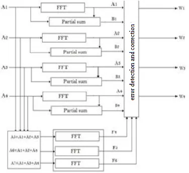
Fig.1 parallel FFT protection using ECC
The original system consists of four FFT modules and three redundant modules is added to detect and correct errors. The inputs to the three redundant modules are linear combinations of the inputs and they are used to check linear combinations of the outputs. For example, the input to the first redundant module is
X5 = x1 + x2 + x3 (1)
And since the DFT is a linear operation, its output z5 can be used to check that
z5 = z1 + z2 + z3. (2)
This will be denoted as c1 check. The same reasoning applies to the other two redundant modules that will provide checks c2 and c3.
The two proposed techniques provide new alternatives to protect parallel FFTs that can be more efficient than protecting each of the FFTs independently. The proposed schemes have been evaluated using FPGA implementations to assess the protection overhead. The results show that by combining the use of ECCs and Parseval checks, the protection overhead can be reduced compared with the use of only ECCs as proposed in [17]. Fault injection experiments have also been conducted to verify the ability of the implementations to detect and correct errors.
III PROPOSED SYSTEM
The two proposed techniques provide new alternatives to protectparallel FFTs that can be more efficient than protecting each of the
FFTs independently.
The proposed schemes have been evaluated using FPGA implementations
to assess the protection overhead. The results show that by combining the use of ECCs and Parseval checks, the protection overhead can be reduced compared with the use of only ECCs as proposed
One of them is the Sum of Squares (SOSs) check that can be used to detect errors.
The SOS check is based on the Parseval theorem that states that the SOSs of the inputs to the FFT are equal to the SOSs of the outputs of the FFT except for a scaling factor. This relationship can be used to detect errors with low overhead as one multiplication is needed for each input or output sample (two multiplications and adders for SOS per sample). For parallel FFTs, the SOS check can be combined with theECC approach to reduce the protection overhead. Since the SOS check can only detect errors, the ECC part should be able to implement the correction. This can be done using the equivalent of a simple parity bit for all the FFTs. In addition, the SOS check is used on each FFT to detect errors. When an error is detected, the output of the parity FFT can be used to correct the error.
This is betterexplained with an example. In Fig. 2, the first proposed scheme isillustrated for the case of four parallel FFTs. A redundant (the parity) FFT is added that has the sum of the inputs to the original FFTs as
Available online: https://edupediapublications.org/journals/index.php/IJR/ P a g e | 4705
using the output of the parity FFT (X) and the rest of the FFT outputs. For example, if an error occurs
in the first FFT, P1 will be set and the error can be corrected by doing
X1c = X − X2 − X3 − X4. (4)
This combination of a parity FFT and the SOS check reduces thenumber of additional FFTs to just one and may, therefore, reduce the protection overhead. In the following, this scheme will be referred to as parity-SOS (or first proposed technique).
Fig. 2. Parity-SOS (first technique) fault-tolerant parallel FFTs.
Fig. 3. Parity-SOS-ECC (second technique) fault-tolerant parallel FFTs
ECC for the SOS checks. Then as in the parity-SOS scheme, anadditional parity FFT is used to correct the errors. This second technique is shown in Fig. 3. The main benefit over the first parity- SOS scheme is to reduce the number of SOS checks needed. The error location process is the same as for the ECC scheme in Fig. 1 and correction is as in the parity-SOS scheme. In the following, thisscheme will be referred to as parity-SOS-ECC (or second proposed technique).
The overheads of the two proposed schemes can be initiallyestimated using the number of additional FFTs and SOS check blocks needed. This information is summarized in Table II for a set of k original FFT modules assuming k is a power of two.
It can be observed that the two proposed schemes reduce the number of additional FFTs to just one. In addition, the second technique also reduces the number of SOS checks. In Section III, a detailed evaluation for an FPGA implementation is discussed to illustrate the relative overheads of the proposed techniques.
For the redundant FFT,the bit widths are extended to 14 and 16 bit, respectively, to cover the larger dynamic range (as the inputs are the sum of several signals). Since both the inputs and outputs to the FFT are sequential, the SOS check is also done sequentially using accumulators that are compared at the end of the block. This is shown in Fig. 5. To minimize the impact of round offs on the fault coverage; the outputs of the accumulator are 39-bit wide. For the evaluation, several values of the number of parallel FFTs are considered.
Available online: https://edupediapublications.org/journals/index.php/IJR/ P a g e | 4706
Fig.4 Implementation of partial summation.
IV RESULTS
SIMULATION RESULT:
SYNTHESIS RESULTS:
The developed project is simulated and verified their functionality. Once the functional verification is done, the RTL model is taken to the synthesis process using the Xilinx ISE tool. In synthesis process, the RTL model will be converted to the gate level netlist mapped to a specific
technology library. Here in this Spartan 3E family, many different devices were available in the Xilinx ISE tool. In order to synthesis this design the device named as ―XC3S500E‖ has been chosen and the package as ―FG320‖ with the device speed such as ―-4‖.
This designis synthesized and its results were analyzed as follows
RTL SCHEMATIC:
Available online: https://edupediapublications.org/journals/index.php/IJR/ P a g e | 4707
TIMING REPORT;
V CONCLUSION
In this brief a new and simple technique was introduces presence of parallel filters to achieve fault tolerance has been presented. in existing we are used only ECC technique, but in this project we improved protection schemes, combine the use of error correction codes and Parseval checks are proposed and evaluated two techniques . The proposed techniques have been evaluated both in termsof implementation complexity and error detection capabilities.
The results show that the second technique, which uses parity FFT and a set of SOS checks that form an ECC, provides the best results in terms of implementation complexity.
REFERENCES
[1] N. Kanekawa, E. H. Ibe, T. Suga, and Y. Uematsu, Dependability in Electronic Systems: Mitigation of Hardware Failures, Soft Errors, and Electro-Magnetic Disturbances. New York, NY, USA: Springer-Verlag,2010. [2] R. Baumann, ―Soft errors in advanced computer systems,‖ IEEE Des. Test Comput., vol. 22, no. 3, pp. 258– 266, May/Jun. 2005.
[3] M. Nicolaidis, ―Design for soft error mitigation,‖ IEEE Trans. Device Mater. Rel., vol. 5, no. 3, pp. 405–418, Sep. 2005.
[4] A. L. N. Reddy and P. Banerjee, ―Algorithm-based fault detection for signal processing applications,‖ IEEE Trans. Comput., vol. 39, no. 10,
pp. 1304–1308, Oct. 1990.
[5] T. Hitana and A. K. Deb, ―Bridging concurrent and non-concurrent error detection in FIR filters,‖ in Proc. Norchip Conf., Nov. 2004,
pp. 75–78.
[6] S. Pontarelli, G. C. Cardarilli, M. Re, and A. Salsano, ―Totally fault tolerant RNS based FIR filters,‖ in Proc. 14th IEEE Int. On-Line TestSymp. (IOLTS), Jul. 2008, pp. 192– 194.
[7] B. Shim and N. R. Shanbhag, ―Energy-efficient soft error-tolerant digital signal processing,‖ IEEE Trans. Very Large Scale Integr. (VLSI) Syst., vol. 14, no. 4, pp. 336–348, Apr. 2006.
[8] E. P. Kim and N. R. Shanbhag, ―Soft N-modular redundancy,‖ IEEE Trans. Comput., vol. 61, no. 3, pp. 323– 336, Mar. 2012.
[9] J. Y. Jou and J. A. Abraham, ―Fault-tolerant FFT networks,‖ IEEE Trans. Comput., vol. 37, no. 5, pp. 548– 561, May 1988.
[10] S.-J. Wang and N. K. Jha, ―Algorithm-based fault tolerance for FFT networks,‖ IEEE Trans. Comput., vol. 43, no. 7, pp. 849–854,
Jul. 1994.
[11] P. P. Vaidyanathanm, Multirate Systems and Filter Banks.Englewood Cliffs, NJ, USA: Prentice-Hall, 1993. [12] A. Sibille, C. Oestges, and A. Zanella, MIMO: From Theory to Implementation. San Francisco, CA, USA: Academic, 2010.
[13] G. L. Stüber, J. R. Barry, S. W. McLaughlin, Y. Li, M. A. Ingram, and
T. G. Pratt, ―Broadband MIMO-OFDM wireless communications,‖ Proc.
IEEE, vol. 92, no. 2, pp. 271–294, Feb. 2004.