Progress In Electromagnetics Research Letters, Vol. 58, 125–131, 2016
A New Method for Designing Low RCS Patch Antenna
Using Frequency Selective Surface
Jun Zheng1, 2, * and Shaojun Fang1
Abstract—A new method for reducing the in-band radar cross-section (RCS) of a patch antenna within its operating frequency is presented. This method is based on the utilization of band-pass frequency selective surface (FSS) consisting of non-resonant constituting elements. The main novelty of this method is that it allows for the use of an FSS structure to reducing the in-band RCS of antennas. To validate the proposed method, a low RCS patch antenna resonating at 5 GHz is designed using this method. The simulated results show that the largest RCS reduction is about 15 dB at 5 GHz. A prototype of the proposed antenna is fabricated and tested in an anechoic chamber, and good agreements between the measured and simulated results are demonstrated.
1. INTRODUCTION
Radar cross-section (RCS) reduction of antennas has drawn more and more attention with the rapid development of the stealth and anti-stealth technology in recent years. Without specific designing for low RCS, the RCS of an antenna is usually much larger than that of a low-observable platform. That is to say, antenna is one of the main contributions to the whole RCS of the low-observable platform. As a result, it has received high priority in the design of all stealth platforms [1].
Antenna RCS is distinctly different for frequencies in the operating band as compared to those out of the operating band. Thus, effective control of antenna RCS must address the in-band and out-of-band frequencies separately. It is well known that frequency selective surfaces (FSSs), both band-pass and stop FSSs, are widely used for out-of band RCS reduction of antennas. A suitable shaped band-pass radome placed in front of the antenna [2–4] or used as the metallic ground of the patch antenna [5] can significantly reduce the out-of-band RCS of any antenna. Besides, the band-stop FSS can be used as backing reflector to reduce the out-of-band RCS [6]. Radar absorber material (RAM) can absorb the electromagnetic wave and convert the energy into heat over a wide frequency band [7–9]. However, methods those are effective out of the operating band will impact the radiating performance of the antenna when they are simply used to reduce the RCS of the antenna within its operating frequency band. Furthermore, the radome, which is indispensable in practice, will influence the effect of RCS reduction when the FSSs are used as the ground of the antenna.
For in-band RCS reduction, shape modification and the use of high impedance surface (HIS) are two effective methods. By cutting off the metallic area of the antenna where the current amplitude is small when it radiates, the antenna can achieve a low RCS while maintaining a good radiation performance [10–12]. The HIS takes advantage of its zero reflect phase to cancel out the reflection waves from the perfect electric conductor (PEC) of the antenna [13, 14]. However, the gain of the antenna will decrease.
Received 27 December 2015, Accepted 14 January 2016, Scheduled 29 January 2016
* Corresponding author: Jun Zheng (zhengjun [email protected]).
1 School of Information Science and Technology, Dalian Maritime University, Dalian 116026, China. 2Beijing Electro-Mechanical
The aim of this paper is to provide a new method to reduce the in-band RCS of antenna using band-pass FSS with non-resonant constituting elements. If we regard the upper layer of the FSS as the radome, this method also opens the way for designing low RCS antenna integrating with the radome using FSS. A patch antenna is used as a test case to illustrate this strategy. The design procedure of the low RCS antenna integrated with FSS is presented in Section 2. Then, we study the performance of the proposed antenna in Section 3 with simulated and measured results. Finally, the paper is concluded in Section 4.
2. DESIGN PROCEDURE OF THE PROPOSED ANTENNA
2.1. Design Strategy of the Antenna with Low RCS in Its Working Frequency Band
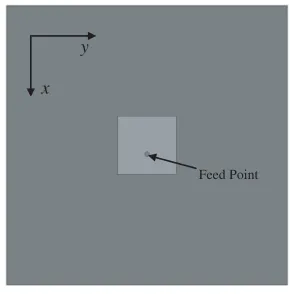
To validate the effect of this method, a common patch antenna working at 5 GHz is chosen as a reference antenna. The geometry of the reference antenna is shown in Fig. 1. The antenna is printed on a substrate with a permittivity of 2.65 and a thickness of 2 mm.
y
x
Feed Point
Figure 1. Geometry of the reference antenna with solid ground plane.
In order to achieve a low RCS antenna in its operating band, we need to design a band-pass FSS whose resonance frequency band covers the operating band of the antenna. However, a band-pass FSS with one layer used as the metallic ground of a patch antenna will definitely deteriorate the radiation performance of the antenna. To tackle this problem, a two-layer band-pass FSS with non-resonant constituting elements is designed. The two layers of the periodic structures are separated by an air-gap. One layer of the periodic structure acts as a superstrate and the other layer of the periodic structure is printed on the same dielectric substrate of the patch antenna working as a ground plane. Because the constituting elements of the band-pass FSS are non-resonant, both periodic structures demonstrate a low transmission coefficient in the antenna operating frequency band. So the patch antenna and the FSS structure form a Febry-Peror (F-P) [15, 16] cavity to maintain a good radiation performance.
2.2. Design of Band-pass FSS with Non-Resonant Constituting Elements
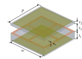
The three-dimensional (3-D) topology and side view of the proposed band-pass FSS is shown in Fig. 2. The FSS consists of two layers of periodic structures separated by an air gap. The upper layer is made up of a periodic array of metallic patches backed by a dielectric substrate. The lower layer is composed of a wire mesh and periodic array of metallic patches printed on each side of a dielectric substrate. The design procedure of the FSS with non-resonant elements is presented in detail in [17]. The main aim of this paper is to provide a method to design a low RCS antenna, so we give the final structure of the FSS without the discussion of the equivalent circuit. Fig. 3 shows the unit cell of the band-pass FSS. The permittivity of both the upper and lower substrates is 2.65. Other parameters are as follows:
Capacitive Patches Inductive Grid Dielectric Substrate Capacitive Patches Inductive Grid Dielectric Substrate Air Gap x y z (a) (b)
Figure 2. Topology of the proposed band-pass FSS. (a) 3-D view and (b) side view.
1 t 2 t 3 t p w g
Figure 3. Unit cell of the proposed FSS.
Figure 4. Simulated frequency response of the FSS for TE-polarization at different incident angles: transmission (TTE) and reflection (RTE) coefficients.
Figure 5. Simulated frequency response of the FSS for TM-polarization at different incident angles: transmission (TTM) and reflection (RTM) coefficients.
The simulated frequency responses of the proposed band-pass FSS for TE- and TM-polarizations at different incident angles are given in Fig. 4 and Fig. 5, respectively. The frequency response is reasonably stable at 5 GHz for both TE- and TM-polarizations up to 45◦. When the incident wave is oblique, the electric fields of TE and TM waves are different for the FSS. As a result, the responses of the FSS for TE and TM waves are different. The reflection coefficients of the two layers of the FSS are shown in Fig. 6. It can be seen that both reflection coefficients are relatively large. Therefore, when the lower layer of the FSS works as the ground plane of the patch antenna, the decrease of the gain is small. Moreover, the gain decrease will be compensated by the upper layer of the FSS working as a superstrate.
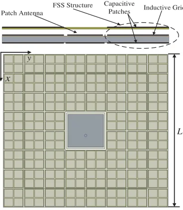
2.3. Geometry of the Low RCS Antenna
Figure 6. Reflection coefficients of the lower and upper layers of the FSS structure.
Patch Antenna
FSS Structure
L Capacitive
Patches Inductive Grid
x
y
Figure 7. Geometry of the proposed low RCS antenna using the band-pass FSS (L= 80 mm).
Figure 8. Photograph of the proposed antenna measured in the anechoic chamber.
Figure 9. Comparison between the S11
parameter of the reference and proposed antennas.
3. RESULTS
To validate the simulated results, the antennas are fabricated and measured. Fig. 8 gives a photograph of the proposed antenna measured in the anechoic chamber.
Figure 9 shows the comparison of S11 parameters between the proposed and reference antennas.
(a) (b)
Figure 10. Simulated and measured radiation patterns of the reference and proposed antennas at 5 GHz. (a) xoz-plane, (b)yoz-plane.
(a) (b)
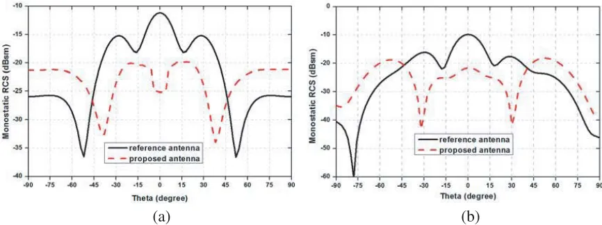
Figure 11. Comparison between the RCS of the reference and proposed antennas for a normally impinging plane wave with (a) horizontal polarization and (b) vertical polarization.
(a) (b)
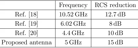
Table 1. Comparison of the in-band RCS reduction between previous literatures and this work.
Frequency RCS reduction
Ref. [18] 10.52 GHz 12.7 dB
Ref. [19] 6.02 GHz 8 dB
Ref. [20] 4.4 GHz 10 dB
Proposed antenna 5 GHz 15 dB
Table 1 presents the in-band RCS reduction comparison between our proposed low RCS antenna and those in the previously reported works [18–20]. It can be seen that the proposed antenna has a good characteristic of low RCS.
4. CONCLUSION
In this paper, a band-pass FSS consisting of non-resonant constituting elements is used to reduce the in-band RCS of a patch antenna. The results show that the utilization of a band-pass FSS with non-resonant constituting elements is an efficient method for in-band RCS reduction of a patch antenna. The RCS reduction in the operating band of the proposed antenna is as much as 15 dB compared with that of the reference antenna while obtaining a gain improvement of 0.2 dB gain. So the proposed antenna provides a good method to reduce the in-band RCS of the antenna while achieving the gain enhancement. It also provides a method for designing low RCS antenna integrating with radome using FSS when we treat the upper layer of the FSS as a radome.
REFERENCES
1. Jenn, D. C., “Radar and laser cross section engineering,” American Institute of Aeronautics and Astronautics, 2005.
2. Knott, E. F., J. F. Shaeffer, and M. T. Tuley, Radar Cross Section, SciTech Pub., Raleigh, NC, USA, 2004.
3. Munk, B. A.,Frequency Selective Surface, Theory and Design, Wiley, New York, NY, USA, 2000. 4. Munk, B. A.,Finite Antenna Arrays and FSS, John Wiley and Sons, Inc., 2005.
5. Genovesi, S., F. Costa, and A. Monorchio, “Low-profile array with reduced radar cross section by using hybrid frequency selective surface,” IEEE Trans. Antennas Propag., Vol. 60, No. 5, 2327– 2335, 2012.
6. Wang, W.-T., S.-X. Gong, X. Wang, H.-W. Yuan, J. Ling, and T.-T. Wan, “RCS reduction of array antenna by using bandstop FSS reflector,” Journal of Electromagnetic Waves and Applications, Vol. 23, Nos. 11–12, 1505–1514, 2009.
7. Gao, Q., Y. Yin, D.-B. Yan, and N.-C. Yuan, “Application of metamaterials to ultra-thin radar absorbing materials design,”Electron. Lett., Vol. 41, No. 17, 936–937, 2005.
8. Li, Y., H. Zhang, Y. Fu, and N. Yuan, “RCS reduction of ridged wave-guide slot antenna array using EBG radar absorbing material,” IEEE Antennas Wireless Propag. Lett., Vol. 7, 473–476, 2008.
9. Genovesi, S., F. Costa, and A. Monorchio, “Wideband radar cross section reduction of slot antennas arrays,” IEEE Trans. Antennas Propag., Vol. 62, No. 1, 163–173, 2014.
10. Xu, H. Y., H. Zhang, K. Lu, and X.-F. Zeng, “A holly-leaf-shaped monopole antenna with low RCS for UWB application,”Progress In Electromagnetics Research, Vol. 117, 35–50, 2011.
12. Dikmen, C. M., S. Cimen, and G. Cakir, “Planar octagonal-shaped UWB antenna with reduced radar cross section,”IEEE Trans. Antennas Propag., Vol. 62, No. 6, 2946–2953, 2014.
13. He, W., R. Jin, J. Geng, and G. Yang, “2×2 array with UC-EBG ground for low RCS and high gain,”Microw. Opt. Technol. Lett., Vol. 49, No. 6, 1418–1422, 2007.
14. Zhang, J., J. Wang, M. Chen, and Z. Zhang, “RCS reduction of patch array antenna by electromagnetic band-gap structure,” IEEE Antennas Wireless Propag. Lett., Vol. 11, 1048–1051, 2012.
15. Feresidis, A. P., G. Goussetis, S. Wang, and J. C. Vardaxoglou, “Artificial magnetic conductor surface and their application to low-profile high-gain planar antennas,” IEEE Trans. Antennas Propag., Vol. 53, No. 1, 209–215, 2005.
16. Weily, A. R., T. S. Brid, and Y. J. Guo, “A reconfigurable high-gain partially reflecting surface antenna,” IEEE Trans. Antennas Propag., Vol. 56, No. 11, 3382–3390, 2008.
17. Al-Joumayly, M. A. and N. Behdad, “A generalized method for synthesizing low-profile band-pass frequency selective surface with non-resonant constituting elements,” IEEE Trans. Antennas Propag., Vol. 58, No. 12, 2946–2953, 2010.
18. Liu, Y. and X. Zhao, “Perfect absorber metamaterial for designing low-RCS patch antenna,”IEEE Antennas Wireless Propag. Lett., Vol. 13, 1473–1476, 2014.
19. Xu, W., J. Wang, M. Chen, Z. Zhang, and Z. Li, “A novel microstrip antenna with composite patch structure for reduction of in-band RCS,”IEEE Antennas Wireless Propag. Lett., Vol. 14, 139–142, 2015.