A Compact Miniaturized Frequency Selective Surface with Stable
Resonant Frequency
Ning Liu1, *, Xian-Jun Sheng2, and Jing-Jing Fan2
Abstract—A compact miniaturized frequency selective surface (FSS) with stable resonant frequency is proposed in this letter. The proposed FSS is composed of four spiral triangles connected in the middle of the unit cell, symmetrically. Simulated results show that the dimension of the element is only 0.0558λ0×0.0558λ0, and reduction in FSS size is up to 97.7% with respect to conventional cross-dipole
FSS operating at the same frequency of 2.7 GHz. Also, the proposed FSS has great angular stability, and the resonant frequency deviation keeps below 0.4% for both TM and TE polarizations of 60◦ incident angle.
1. INTRODUCTION
Frequency selective surfaces (FSSs) are one- or two-dimensional periodic structures and have been widely applied to construct antenna reflectors, hybrid radomes, optical filters, high impedance surfaces and electromagnetic shields [1]. Theoretically, FSSs are infinite and planar structures. However, in practical applications, FSSs are usually applied in limited space. In order to make the finite FSS perform the characteristics of the original infinite one, the constituting element should be small enough. For this purpose, different methods and structures have been proposed to realize the miniaturization of FSS in recent years. Miniaturized FSS made up of a periodic array of metallic patches separated by thin air-gaps backed by a wire mesh is proposed in [2]. Two layers of metallic unit cell are proposed to realize a miniaturized FSS in [3]. Slot type FSSs overlaid with a periodic array of metallic patches mounted on an ultra-thin dielectric layer are proposed in [4] to realize miniaturized FSS. A novel miniaturized FSS is achieved by bending the edge of square loop aperture into the inner space is proposed in [5]. A convoluted ring slot is adopted to construct miniaturized FSS in [6], miniaturized FSSs based on metallic meander lines are proposed in [7–10], and compact miniaturized FSS based on Y-type element is proposed in [11]. Also, substrate integrated waveguide (SIW) technology [12], lumped reactive components [13] and complementary structures [14] are applied to realize the miniaturization of FSS.
A single layer FSS consisting of novel miniaturized structure based on spiral triangle element is proposed in this letter. Compared to the aforementioned structures the proposed FSS has better miniaturization and stability with respect to different polarization and incident angles. And the proposed FSS is more than 97.7% smaller compared to the conventional cross-dipole FSS at the same resonant frequency.
2. DESIGN OF THE PROPOSED FSS
Usually, the resonant frequency of FSS can be simply analyzed with equivalent circuit model [15]. According to the equivalent circuit theory, if the incident electric field is perpendicular to the gap between metallic lines, the gap behaves in the long wavelength regime as capacitive component in
Received 6 July 2016, Accepted 26 August 2016, Scheduled 30 August 2016
* Corresponding author: Ning Liu ([email protected]).
1 School of Mechanical Engineering, Dalian University of Technology, Dalian 116024, China. 2 School of Electrical Engineering,
equivalent circuit model. Whereas, when the electric field is parallel to the metallic line, the metallic line can be modelled by an inductive component. Then, the resonant frequency of FSS can be determined by f = 1/(2π√LC), where L and C represent the equivalent inductance and capacitance of FSS, respectively. Obviously, the resonant frequency can be decreased by increasing the equivalent inductance and capacitance, simultaneously.
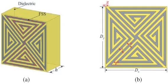
As shown in Fig. 1, the proposed FSS consists of four spiral triangles connected in the middle of unit cell, symmetrically. This compact spiral triangle design increases the length of the current flowing marked by a dashed line in Fig. 1, which means the increase of the equivalent inductance. And by narrowing the width of slits between metallic lines, the equivalent capacitance can be increased greatly. As discussed above, the increase of the equivalent inductance and capacitance will result in the decrease of resonant frequency and, hence, miniaturization characteristic can be achieved. Moreover, the central-symmetry design will improve the stability with respect to different polarizations and incident angles.
(a) (b)
Figure 1. Structure of a unit cell. (a) Perspective view. (b) Top view.
3. SIMULATED AND MEASURED RESULTS
To investigate the performance of the proposed FSS, simulation and experimental validations have been carried out in succession. Structure parameters of FSS are defined as follows: dimension of FSS is Dx = Dy = 6.2 mm, width of metallic line is w = 0.2 mm, width of slit between metallic line is
s= 0.2 mm, width of gap on the edge is g = 0.1 mm and tortuous angle of spiral triangle is α = 45◦. And the FSS is mounted on one side of substrate with relative permittivity εr = 2.65, loss tangent tanδ = 0.001 and thicknessh= 1 mm.
Transmission coefficients under different polarizations and incident angles have been analyzed with commercial software HFSS. Periodic boundary conditions (PBC) are applied to the four sides of the unit cell to imitate the infinite surface, and “Floquet Port” has been adopted in HFSS to set polarization and incident angle. And the simulated frequency ranges from 1 GHz to 5 GHz with a step of 0.01 GHz. Firstly, transmission coefficients with different polarizations under normal incidence are investigated. As shown in Fig. 2(a), the resonant frequency is 2.7 GHz, and its unit cell size is approximately 0.0558λ0 ×0.0558λ0, where λ0 is the resonant wavelength in free space. Moreover,
the transmission coefficients of the proposed FSS keep almost the same under different polarization angles.
Secondly, transmission coefficients at oblique incidence are simulated. It can be observed in Fig. 2(b) that the resonant frequency is almost fixed, and the filter property is maintained well, even the incident angle reaches 60◦. The resonant frequency deviation of 60◦incident angle is only 0.37% and 0.4% for TE and TM polarization, respectively.
(a) (b)
Figure 2. Simulated transmission coefficients of the proposed FSS. (a) For different polarization angles. (b) For different incident angles.
(a) (b)
Figure 3. Surface current distribution diagrams at 2.7 GHz. (a) TE polarization. (b) TM polarization.
The angular stability of the proposed FSS can be analyzed by its transmission line model. As shown in Fig. 4, the reflection coefficient can be calculated by
Γ =− RA
RA+jωL+ 1/jωC (1)
As discussed in [16], if the dimensions of the FSS are smaller than 0.35λ, the changes ofjωL+1/jωC in (1) can be ignored which means that the resonant frequency angle stability is great. In our design,
Dx and Dy are about 0.0558λ, which are much smaller than 0.35λ. Hence, great angular stability can be obtained.
For comparison purpose, a reference FSS (conventional cross-dipole FSS) operating at the same resonant frequency of 2.7 GHz as the proposed FSS is also implemented. Fig. 5 shows comparison of transmission coefficient between the miniaturized FSS and reference FSS at normal incidence. Table 1 shows the dimension comparison between the miniaturized FSS and reference FSS.
Table 1. Size comparison between miniaturized element and the conventional cross-dipole element.
Element type Width of metallic line (mm) Dimension (mm) Element area (mm2)
Miniaturized element 0.2 6.2 38.44
Figure 4. Transmission line model of the proposed FSS.
Figure 5. Transmission coefficients of the miniaturized FSS and reference FSS.
Figure 6. Transmission coefficient of the FSS of different material permittivity.
Figure 7. Photograph of the fabricated
miniaturized FSS.
As shown in Table 1 and Fig. 5, for the same resonant frequency at 2.7 GHz, the proposed FSS has a dimension of 6.2 mm, whereas dimension of the conventional cross-dipole FSS is 41.4 mm. Hence, a size reduction of 97.7% is achieved. Meanwhile, the−10 dB bandwidths of the two FSSs are almost the same.
Subsequently, the effect of relative permittivity has been investigated. Transmission coefficients of the FSSs with different relative permittivities are shown in Fig. 6. It can be found that the higher the relative permittivity is, the lower the resonant frequency is, which means that a higher relative permittivity will result in a better miniaturization characteristic.
For further verification of the excellent miniaturization and angular stability characteristic of the proposed FSS structure, comparisons between the structures in previous papers have been carried out, and the results are presented in Table 2. From the comparison, it can be observed that the proposed FSS improves the miniaturization and angular stability performance.
Table 2. Results of comparison to other FSSs.
εr FSS structure Unit cell size Frequency deviation
TE TM
2.2 Structure in [10] 0.067λ0×0.067λ0 0.91% 1.21% Structure proposed 0.059λ0×0.059λ0 0.43% 0.45%
2.65 Structure in [9] 0.058λ0×0.058λ0 0.57% 3.7% Structure proposed 0.0558λ0×0.0558λ0 0.37% 0.4%
4.4 Structure in [7] 0.104λ0×0.104λ0 1.7% 1.9% Structure proposed 0.046λ0×0.046λ0 0.13% 0.2%
5.0 Structure in [8] 0.061λ0×0.061λ0 0.52% 2.1% Structure proposed 0.044λ0×0.044λ0 0.4% 0.4%
Measured transmission coefficients under different incident angles and polarizations are shown in Fig. 8. It can be observed that transmission coefficients are stable for various incident angles within 60◦ and different polarizations. Also, good agreements between simulated and measured results can be observed. And the ripples of the measured results are caused by edge diffraction. Although the measured results are not ideal compared with the simulated ones, they still demonstrate the properties of the proposed FSS.
(a) (b)
Figure 8. Comparisons between simulated and measured results. (a) TE polarization. (b) TM polarization.
4. CONCLUSION
A novel compact miniaturized FSS is proposed in this letter. Miniaturization characteristic is achieved by the symmetrical spiral triangle structure to lengthen the resonant length, and the area of this proposed FSS is reduced by 97.7% at the same operation frequency of 2.7 GHz, compared with the conventional cross-dipole FSS. Simulated and experimental results show that this miniaturized FSS has great polarization and angular stability, and the resonant frequency deviation keeps below 0.4% of incident angle 60◦ for both TE and TM polarizations. By virtues of these merits, the proposed FSS will be of significance for practical applications in limited space, such as antenna reflectors.
ACKNOWLEDGMENT
REFERENCES
1. Munk, B. A.,Frequency Selective Surfaces: Theory and Design, Wiley, New York, 2000.
2. Sarabandi, K. and N. Behdad, “A frequency selective surface with miniaturized elements,” IEEE Trans. Antennas Propag., Vol. 55, No. 5, 1239–1245, 2007.
3. Deng, F., X. Q. Yi, and W. J. Wu, “Design and performance of a double layer miniaturized-element frequency selective surface,” IEEE Antennas Wirel. Propag. Lett., Vol. 12, No. 5, 721–724, 2013. 4. Lin, B. Q., S. H. Zhou, X. Y. Da, Y. W. Fang, Y. J. Li, and W. Li, “Compact miniaturized-element
frequency selective surface,” Electron. Lett., Vol. 51, No. 12, 883–884, 2015.
5. Yang, H.-Y., S.-X. Gong, P.-F. Zhang, F.-T. Zha, and J. Ling, “A novel miniaturized frequency selective surface with excellent center frequency stability,” Microw. Opt. Technol. Lett., Vol. 51, 2513–2516, 2009.
6. Yang, L.-H., Z.-F. Wang, Z.-Y. Zong, W. Wu, and D.-G. Fang, “A miniaturized frequency selective surface based on convoluted ring slot,”Proc. 6th Asia-Pacific Conf. Environ. Electromagn., 63–66, Nov. 2012.
7. Chiu, C.-N. and K.-P. Chang, “A novel miniaturized-element frequency selective surface having a stable resonance,” IEEE Antennas Wireless Propag. Lett., Vol. 8, 1175–1177, 2009.
8. Yang, G., T. Zhang, W. Li, and Q. Wu, “A novel stable miniaturized frequency selective surface,”
IEEE Antennas Wirel. Propag. Lett., Vol. 9, 1018–1021, 2010.
9. Yan, M., S. Qu, J. Wang, J. Zhang, A. Zhang, S. Xia, and W. Wang, “A novel miniaturized frequency selective surface with stable resonance,”IEEE Antennas Wireless Propag. Lett., Vol. 13, 639–641, 2014.
10. Azemi, S. N., K. Ghorbani, and W. S. T. Rowe, “Angularly stable frequency selective surface with miniaturized unit cell,” IEEE Microw. Wireless Compon. Lett., Vol. 25, No. 7, 454–456, 2015. 11. Wu, R., H. Zhang, Z.-M. Yang, T. Zhong, and Y. Lin, “Compact stable frequency selective surface
using novel Y-type element,” Progress In Electromagnetics Research Letters, Vol. 57, 85–90, 2015. 12. Xu, R.-R., Z.-Y. Zong, and W. Wu, “Low frequency miniaturized dual band frequency with close
band spacing,” Microw. Opt. Technol. Lett., Vol. 51, No. 5, 1238–1240, 2009.
13. Liu, H. L., K. L. Ford, and R. J. Langley, “Design methodology for a miniaturized frequency selective surface using lumped reactive components,” IEEE Trans. Antennas Propag., Vol. 57, 2732–2738, 2009.
14. Hu, X.-D., X.-L. Zhou, L.-S. Wu, L. Zhou, and W.-Y. Yin, “A miniaturized dual-band frequency selective surface (FSS) with closed loop and its complementary pattern,”IEEE Antennas Wireless Propag. Lett., Vol. 8, 1374–1377, 2009.
15. Langley, R. J. and E. A. Parker, “Double-square frequency-selective surfaces and their equivalent circuit,” Electron. Lett., Vol. 19, No. 17, 675–677, 1983.