University of South Carolina
Scholar Commons
Theses and Dissertations
2017
Mechanical Characterization and Non-Destructive
Evaluation of SiCF-SiCM Composite Tubing with
the Impulse Excitation Technique
Nathaniel Truesdale University of South Carolina
Follow this and additional works at:https://scholarcommons.sc.edu/etd Part of theNuclear Engineering Commons
This Open Access Thesis is brought to you by Scholar Commons. It has been accepted for inclusion in Theses and Dissertations by an authorized administrator of Scholar Commons. For more information, please [email protected].
Recommended Citation
Mechanical Characterization and Non-Destructive Evaluation of SiC
F-SiC
MComposite Tubing with the Impulse Excitation Technique
by
Nathaniel Truesdale
Bachelor of Science
University of South Carolina, 2015
Submitted in Partial Fulfillment of the Requirements
For the Degree of Master of Science in
Nuclear Engineering
College of Engineering and Computing
University of South Carolina
2017
Accepted by:
Xinyu Huang, Director of Thesis
Jing Jing Bao, Reader
DEDICATION
This work is dedicated to the men and women in the Engineering community that
have devoted their lives to the advancement of modern society. To be a part of the
Engineering field is to a part in shaping the future. It is both a responsibility and a privilege
to ensure the longevity of the human race and to pursue all knowledge of the natural world.
This is also dedicated to all the previous members of the scientific community that have in
ACKNOWLEDGEMENTS
I would like to acknowledge and express my deepest appreciation to Dr. Xinyu
Huang and my coworkers in the lab, who all provided me ample opportunity and support
to perform research throughout my Graduate education. In addition, I would like to
acknowledge Dr. George Jacobsen and Kirill Shapovalov of General Atomics for providing
research material and well needed feedback throughout this work.
This work was performed at the University of South Carolina, Mechanical
Engineering Department, in collaboration with General Atomics. Funding was provided by
the Department of Energy Office of Nuclear Energy under the Accident Tolerant Fuel
Program, DE-NE0000566 and DE-NE0008222. This report was prepared as an account of
work partially sponsored by an agency of the United States Government. Neither the
United States Government nor any agency thereof nor any of their employees make any
warranty, express or implied, or assumes any legal liability or responsibility for the
accuracy, completeness, or usefulness of any information, apparatus, product, or process
disclosed, or represents that its use would not infringe privately owned rights. Reference
herein to any specific commercial product, process, or service by trade name, trade mark,
manufacturer, or otherwise does not constitute or imply its endorsement, recommendation,
or favoring by the United States Government or any agency thereof. The views and
opinions of the authors expressed herein do not necessarily state or reflect those of the
ABSTRACT
With growing interest on ceramic fiber reinforced ceramic matrix composites
(CMC) for accident tolerant fuel, the need for mechanical characterization of ceramic
composite arises. It has been of particular interest to non-destructively evaluate the
mechanical performance of these composites. Impulse excitation (IE) is a well-established
method for non-destructive mechanical characterization of homogeneous isotropic material
of well-defined shapes. In this thesis, impulse excitation technique was applied for
non-destructive characterization of composite tube for the first time as far as we know. CMC,
when stressed beyond its damage threshold, will experience various forms of structural
damage, such as matrix micro-cracking, fiber-matrix debonding, and fiber breakage. The
effects of damage on its vibrational frequency and damping were studied using the impulse
excitation technique.
Nuclear fuel cladding can experience both tensile and compressive stress, however,
most mechanical testing is conducted by putting it under tensile stress: the examples are
uniaxial tensile test and internal pressure burst test. Little experimentation involving
compression of CMC tubing via external pressure has been performed previously. In this
thesis, the mechanical behavior of CMC under compressive stress up to the point of
material failure was studied using an adapted rubber plug compression technique and with
The experimentation performed in this thesis focuses on: 1) the utilization of
impulse excitation as a non-destructive evaluation method to determine mechanical
properties and to monitor the damage of silicon carbide fiber reinforced silicon carbide
matrix (SiCf-SiCm) composite tubing, and 2) the mechanical characterization of SiCf-SiCm
composite tubing under external pressure. In the first focus, novel configuration for
enabling the impulse excitation measurement of slender tube was developed. The method
was first validated on tubes of well-characterized materials under free-free and
clamped-free configurations. Validation testing of all IE setups resulted in less than 6% deviation of
mechanical properties when compared to published values. Afterwards, IE was performed
on undamaged SiCf-SiCm composite tubular samples to obtain axial elastic modulus and
shear modulus. The measured properties fell within 4.1% of the same properties obtained
from conventional tension and torsion tests. The IE techniques were found to be relatively
simple, quick, and highly accurate for obtaining elastic properties of composite tubes.
In addition, the effectiveness of IE method for detecting damage in CMC tube was
studied experimentally. Progressive damage in the ceramic composite tube were gradually
induced by subjecting it to internal pressurization cycles. Incremental pressure was applied
in these loading cycles to levels over the proportional limit stress (PLS) of the CMC. The
occurrence of damage was confirmed by acoustic emission monitoring. IE was performed
after each pressurization cycle to detect the changes to its vibrational response under
fixed-free boundary conditions. It was noted the presence of micro-cracking and other form of
composite damage decrease natural frequency while increasing its vibrational damping.
sensitive and change monotonically with material damage. As such they can serve as
effective damage indicators for CMC.
The second focus was to study the mechanical response of the composite tube under
compressive stress. The experiment involved compressing the outer surface of a CMC tube
while measuring hoop strain on the internal surface. The compression test is to simulate
the pressurized coolant acting on nuclear fuel during typical Light Water Reactor (LWR)
operation. A novel external expanding plug method for applying external pressure to the
sample tube was developed and validated on known material. SiCf-SiCm composite tubing
was then tested to failure and mechanical compressive stress-strain responses were
observed. It was found compressive behavior of CMC was significantly different than the
tensile behavior. There is a lack of pronounced “bending” as shown in typical tensile
stress-strain curve of CMC. In the course of the study, delicate techniques were developed
to install small foil strain gauge on the internal curved surface of small bore tubing. It was
found that both curvature and internal pressure affect the strain reading from gauge
TABLE OF CONTENTS
DEDICATION ... iii
ACKNOWLEDGEMENTS ... iv
ABSTRACT ... v
LIST OF TABLES ... xi
LIST OF FIGURES ... xii
LIST OF ABBREVIATIONS ... xv
CHAPTER 1: INTRODUCTION ... 1
1.1 Silicon Carbide Composite Cladding ... 1
1.2 Composite Damage ... 4
1.3 Characterization of SiCf-SiCm Composites Cladding ... 7
1.4 Nondestructive Testing Methods ... 8
1.5 Impulse Excitation ... 14
1.6 Application of Impulse Excitation ... 19
1.7 IE Testing of SiC Composites: ... 24
CHAPTER 2: EXPERIMENTAL SETUP ... 27
2.1 Tension Setup ... 27
2.2 Torsion Setup ... 30
2.4 Mechanical Validation ... 34
2.5 Table Mounted Impulse Excitation ... 36
2.6 Pressure Rig Mounted Impulse Excitation... 39
2.7 Validation of Impulse Excitation ... 43
2.8 Instrumentation ... 44
2.9 Internal Strain Gauge Study ... 48
2.10 Acoustic Emission Analysis ... 55
CHAPTER 3: RESULTS AND DISCUSSION ... 57
3.1 Testing Overview ... 57
3.2 Tension Validation ... 58
3.3 Torsion Validation ... 59
3.4 Internal Pressure Validation ... 60
3.5 Table Mounted IE Validation ... 61
3.6 Pressure Rig Mounted IE Validation ... 63
3.7 Initial Table Mounted Impulse Excitation ... 65
3.8 Sample 13464-17-06-1 Mechanical Testing ... 66
3.9 Samples 13464-17-06-2 and 3 Pressure Loading and IE testing ... 72
3.10 Compression and Internal Strain Gauge Study ... 80
CHAPTER 4: CONCLUSIONS ... 93
REFERENCES ... 98
A.1 Purpose ... 104
A.2 Derivation ... 104
A.3 Procedure ... 106
APPENDIX B – BEAM VIBRATION DERIVATION... 109
B.1 Transverse Beam vibration ... 109
B.2 Axial Vibration ... 113
LIST OF TABLES
Table 1. 1: List of Advantages and Disadvantages of various NDT techniques ... 13
Table 3. 1: Results from Table Mounted IE validation testing. Percent errors are in regards to values from published literature…………...63
Table 3. 2: Results from Rig Mounted IE validation testing. Percent errors are in regards to values from published literature. ... 65
Table 3. 3: Results from Rig Mounted IE composite testing. ... 66
Table 3. 4: Tabulated results of mechanical tests for all composite samples ... 75
Table 3. 5: Resulting Moduli from Impulse Excitation testing ... 80
Table 3. 6: Recorded Percent Error between recorded and predicted inner strains for all Aluminum samples and loading. ... 92
Table B. 1: Node Locations of freely supported Transverse Beam Vibration ……….112
LIST OF FIGURES
Figure 1.1: Microscopic Image of CVI SiCf-SiCm composite with a PyC interphase [10] ... 4
Figure 1.2: Plot of damage progression over applied stress to a composite [14] ... 5
Figure 1. 3 Time dependent micro-crack development. [16] ... 6
Figure 1.4: Various internal damages of composite material [13] ... 7
Figure 1.5: Location of Node and Anti-node of Rectangular bar in Flexural vibration ... 14
Figure 1.6: Location of Node and Anti-node of a Rectangular bar in Torsion ... 15
Figure 1.7: Total Acquired Signal from all frequencies recorded by one impulse of the material ... 18
Figure 1.8: Range of Frequencies with corresponding Amplitudes from Fast Fourier Transform ... 19
Figure 2. 1 a (left): Sample adapter nut adhered to the end of sample tube. b (right): Supportive V-block setup to allow adapter nut curing...27
Figure 2.2: Adapters and connectors of a tensile test specimen ... 28
Figure 2.3: Schematic of adapter connector for tension ... 29
Figure 2. 4: Axial tension testing of SiCf-SiCm composite tubing with extensometers [3] ... 29
Figure 2.5: a (left): Schematic of the torsion rig. b (right): Image of sample tube in torsion rig 30 Figure 2.6: Schematic of adapter connector for torsion. ... 31
Figure 2.7: Adapter configuration to transmit torsion to the tubular sample ... 32
Figure 2.8: Image of adapter supporting test sample during internal pressure test ... 33
Figure 2. 9: RFDA System 24 hardware used for IE testing [64] ... 37
Figure 2.10: Recording setup for free-free vibration via table mounted IE ... 38
Figure 2.12: Pressure rig mounted IE setup for flexural and torsional testing ... 40
Figure 2.13: a (left): Flexural vibration microphone and impact setup. B (right): Torsional vibration microphone and impact setup ... 41
Figure 2. 14: CEA-06-062UB-350/P2 strain gauge used for internal strain measurement ... 46
Figure 2. 15: Physical representation of AE timing parameters.[67] ... 47
Figure 2 16: a (left): Attachment configuration of strain gauge prior to installation. b (right): Strain gauge lead attachment and support prior to rubber push tube removal ... 49
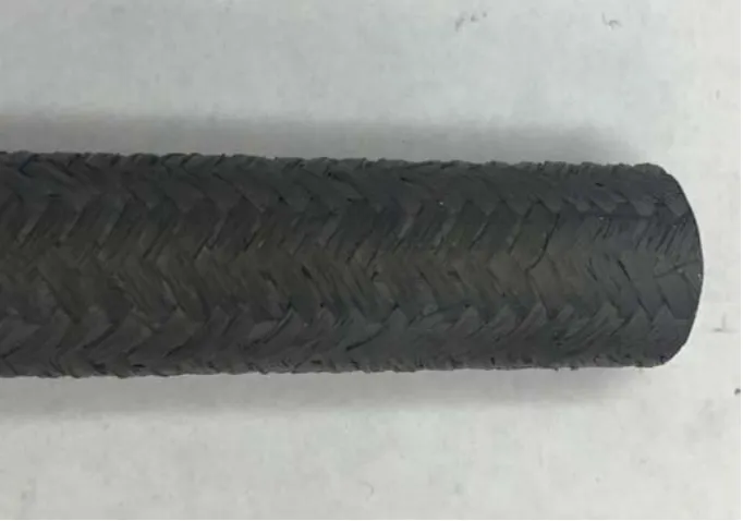
Figure 2. 17: Surface texture for 13444-13-SG-X SiCf-SiCm composite tubing ... 52
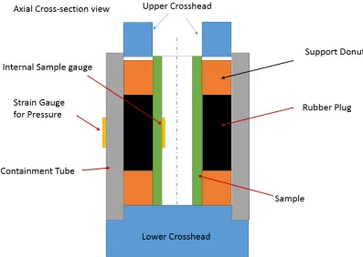
Figure 2. 18: Diagram for Expanding Plug test for external pressure ... 53
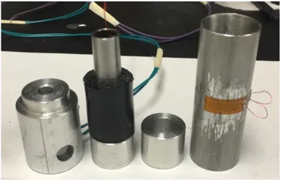
Figure 2. 19: Image of parts required for expanding plug test for external pressure... 54
Figure 3. 1: Plot of load and strain during tension test of Aluminum 6061 tube...59
Figure 3.2: Shear stress-strain plot of Aluminum 6061 torsion ... 60
Figure 3.3: Materials used to validate table mounted impulse excitation. (Left to right) Al 2024Tube, Zircaloy-4 Tube, Al 6061 Bar, and O1 Tool Steel Bar ... 62
Figure 3.4: Materials used to validate rig mounted impulse excitation. (Left to right) Al 6061 Rod, Al 3003 Tube, 4140 Steel Rod, and 4140 Steel Tube. ... 64
Figure 3.5: Stress-Strain plot of tension test performed on Initial SiCf-SiCm composite sample 13464-17-06-01 ... 67
Figure 3.6: Shear Stress-Strain plot of sample 13464-17-06-1 torsion test ... 69
Figure 3.7: Cut section of sample 13464-17-06-1 used for internal burst testing ... 70
Figure 3.8: AE Absolute Energy and pressure found in burst test of sample 13464-17-06-1 ... 71
Figure 3.9: Pressure loading for internal damage to sample 13464-17-06-2 with recorded AE events ... 73
Figure 3.10: Pressure loading for internal damage to sample 13464-17-06-3 with recorded AE events ... 73
Figure 3.11: Resulting frequency and damping changes of sample 13464-17-06-2 with increases to internal pressure... 76
Figure 3.12: Resulting frequency and damping changes of sample 13464-17-06-3 with increases to internal pressure... 76
Figure 3. 14: Stress-strain plots determined from validation testing of 4130 alloy steel ... 83
Figure 3. 15: Expected Inner Hoop Stress for sample 13444-13-SG-1 ... 84
Figure 3. 16: Typical plot of recorded and calculated hoop strains along inner diameter of sample ... 85
Figure 3. 17: Compressive Stress-Strain plot of sample 13444-13-SG-2 with recorded AE ... 86
Figure 3. 18: Crushed 13444-13-SG-2 sample after expanding plug test till failure ... 88
Figure 3.19: Recorded and Calculated Inner strain plot for Sample A during 2000 psi loading ... 89
Figure 3.20: Recorded and Calculated Inner strain plot for Sample B during 2000 psi loading ... 90
Figure 3.21: Recorded and Calculated Inner strain plot for Sample C during 2000 psi loading ... 90
Figure 3.22: Ratio (Correction Factor) between strains observed by gauges attached to curved and flat surfaces based upon differences curvature. [72] ... 92
Figure A. 1: Schematic of rotation for a trifilar pendulum [73]...105
Figure A. 2: Image of upper clamp on support for trifilar pendulum test ... 107
Figure B. 1: First 3 modes of transverse vibration for a freely supported beam...112
LIST OF ABBREVIATIONS
AE ... Acoustic Emission
CFRP ... Carbon Fiber Reinforced Plastics
CMC ... Ceramic Matrix Composite
CVD ... Chemical Vapor Deposited
CVI ... Chemical Vapor Infiltration
DIC ... Digital Image Correlation
ER ... Electrical Resistance
FFT ... Fast Fourier Transformation
HDT ...Hit Definition Time
HLT ... Hit Lockout Time
HP ... Hot Pressing
ID ... Inner Diameter
IET ... Impulse Excitation Technique
LOCA ...Loss of Coolant Accident
NITE ... Nano-Infiltration Transient Eutectic
NDT ... Nondestructive Testing
OD ...Outer Diameter
PDT ... Peak Definition Time
PIP ... Polymer Impregnation/ Pyrolysis
PLS ... Proportional Limit Stress
R&D ...Research and Development
RFDA ... Resonant Frequency and Damping Analyzer
SiC...Silicon Carbide
UTS ...Ultimate Tensile Stress/Strength
CHAPTER 1: INTRODUCTION
1.1Silicon Carbide Composite Cladding
Silicon Carbide fiber reinforced Silicon Carbide matrix (SiCf-SiCm) composite is
a ceramic matrix composite (CMC) that is being considered as an innovative material for
accident tolerant nuclear fuel cladding in the nuclear industry. SiCf-SiCm composites offer
exemplary mechanical and chemical properties such as high temperature stability,
irradiation tolerance, oxidation resistance, and potentially improved toughness compared
to metals. [1,2] Various composite architectures are being studied by research and
development (R&D) groups in the nuclear field. Combinations of the following
configurations are under development and study: monolithic composite layers, Triplex
layers of SiCf-SiCm composites, and bi/ tri-axial braiding of SiCf-SiCm composites. [3] As
a result, great variation in the CMC structure can be obtained with vast differences to
material strength and properties which in a nuclear application can be fabricated to surpass
the current zirconium alloy cladding typically used in modern light water reactors. [3]
SiCf-SiCm composites comprise of three key components. The first are the Silicon
carbide fibers that are bundled together to form structural fiber tows for the material. The
ceramic fibers can set into complex architectures based on the application of the composite
such as woven 2-dimensional fabrics or multidimensional fiber preforms. The fibers
on the direction of the applied stresses to the material. The earliest sets of SiC fibers
included cg-Nicalon and Hi-Nicalon, whose Elastic Modulus in the fiber axial direction
ranged between 170 to 270 GPa. [4] Although the braided cladding composed of these
fibers held satisfactory mechanical advantages compared to alloy cladding, the percent
content of oxygen and carbon in the fibers yielded unwanted crystallization. This then led
to densification of the CMC structure when exposed to moderate levels of neutron
irradiation. Eventual development of hi-Nicalon type S SiC fibers resulted in a more
suitable fiber with greater toughness and irradiation tolerance. An interphase material is
then applied to the ceramic fibers through chemical vapor infiltration (CVI) process. The
function of interphase coating is to adequately deflect matrix micro-cracking from the
structural fibers as composite damage occurs. The ideal interphase coating material should
have a low shear strength to effectively route internal cracking. [5] The third component
of the SiCf-SiCm composite is the SiC matrix which provides rigidity to the composite.
The Silicon carbide matrix can be applied by several different methods; all of which result
in certain advantages and disadvantages to the production of the SiCf-SiCm composite
cladding. [6] Deposition of the Silicon carbide matrix has been performed through the
processes of chemical vapor infiltration(CVI), polymer impregnation/ pyrolysis(PIP),
liquid silicon infiltration(LSI), and slurry infiltration/ hot pressing(HP).
The CVI process involves deposition of SiC by chemical decomposition of gaseous
precursors, such as methlytrichlorosilane (CH3SiCl3), into the porous material until a high
density and crystallinity SiC matrix forms. Despite the long process time, this process
allows for the composite to be performed into a large number of shapes and geometries.
polymers into the fiber architecture until curing and pyrolyzed at temperatures above
1000o C. Several iterations of the PIP process are required to achieve the desired composite
density considering that the precursor polymer shrinks when exposed to high temperatures.
Another method, the liquid silicon infiltration method, involves application of a binding
agent mixed with carbon particulates and SiC filler particles to the ceramic SiC fibers.
After heating the material, liquid silicon is applied to the coated fibers at high temperatures.
A reaction between the carbon and the molten silicon yields the desired Silicon carbide
across the composite with relatively high density. The final fabrication process of SiCf
-SiCm composites is hot pressing in which fine SiC powder, binders, and sintering additives,
such as Al2O3 and Y2O3, are infiltrated into the preform and dried. To complete the
fabrication, the composite material is hot-pressed at temperatures exceeding 1700oC until
densification is achieved. [8] Although mechanical properties of composites produced by
this method are desirable for nuclear cladding applications, hot-pressing is limited on the
geometry and length of material fabricated. Upon comparison between the above methods
for fabrication of SiCf-SiCm composite cladding, there is great interest in CVI fabricated
composites due to their superior mechanical and thermal properties, irradiation
performance, and flexibility in complex component manufacturing. [9] However, a major
drawback for the selection in fabricating SiCf-SiCm composites via CVI is the production
time and cost compared to the rest of the methods. This, coupled with the cost of
Hi-Nicalon Type S Silicon carbide fiber, makes fabrication of nuclear grade CMC cladding
expensive at the current time. [10] Figure 1.1, below, visualizes the microscopic structure
Figure 1.1: Microscopic Image of CVI SiCf-SiCm composite with a PyC interphase [10]
In addition, production of CMC material results in random formation of defects
along the inter-space of the SiCf-SiCm structure during the various fabrication processes
and during the composites useful life. As a result, nondestructive testing methods can be
utilized to not only characterize composite material properties, but to monitor the structural
integrity of the CMC material for internal damage that could not be performed by
conventional testing methods.
1.2 Composite Damage
Non-destructive testing methods are excellent tools used to analyze and monitor
composites for strength and internal damage. NDT methods can be used throughout the
composites life without harming the component and can provide useful information in the
future production of composite structures. [11,12] Composites experience damage in three
stages of life; production of the structural fibers, assembly of the full composite structure,
and service life of the composite after manufacturing. [13] During manufacturing, fibers
may experience damage in the form of thinning or fracture. As a result, the interphase
coating material on the fibers may become compromised and fail which leads to debonding
fibers. Further defects can appear when the matrix material is applied to the fiber preform.
Gas entrapment occurs when the matrix material does not completely adhere to all sections
of the fiber structure. After composite construction, voids in which accumulation of
stresses occurs within the material become present. Voids reduce the overall density and
ultimately reduce the strength of the composite. In addition, further damage, such as
delamination between composite layers, can propagate from void locations. [13] Damage
sustained during the in-service stage of a composites life is typically a result of stress or
fatigue induced upon the material. Sections with defects and initially damaged fibers from
manufacturing are weakened areas of the composite in which mechanical and thermal
stresses cause further damage. In Figure 1.2, below, Telreja shows the four major
categories of composite damage as increasing amounts of stress. These categories are 1)
Matrix cracking, 2) Crack coupling/ interfacial debonding, 3) Delamination, and 4) Fiber
breakage.
Figure 1.2: Plot of damage progression over applied stress to a composite [14]
Matrix cracking occurs earliest in a composites stress loading. This cracking
created from the manufacturing process. As levels of stress increase, densification of
micro-cracking in the composite matrix then leads to the interfacial debonding between the
matrix and the fiber structure. Axial stresses along the fiber directions generate shear forces
acting between the matrix and fiber. [15] Debonding initiates along the edge of a matrix
crack that has exposed a fiber. With increases to axial stress along the fiber direction,
debonded crack fronts continue along the fiber direction until delamination. Delamination
occurs when sufficient interfacial debonding and matrix cracking are present in a
composite to cause detachment of composites layers. Another key characteristic of
delaminate is the large amount of fiber exposure and therefore greatly reduced distribution
of stresses along the material. Telreja indicates that the final phase of composite damage is
fiber breakage.
Figure 1.4: Various internal damages of composite material [13]
For the case of 3 dimensional composite tubular braids, the particular damage
mechanics are the same as in composite plates, however, macro-cracking of material is
dependent on specified loading boundary conditions. Rohmer noted the final material
failure mode in SiCf-SiCm braided tubing under axial and hoop tensile loading. [3] This
study revealed that braided composite tubing under axial tension loading experienced
macro-cracking perpendicular to the axial load similarly to isotropic material tensile
loading. Hoop tensile loading via piston driven internal elastomer insert expansion resulted
in general material fracture along the axial direction of the tubing. In both cases, fiber pull
out was prevalent along the exposed fractured edges of the braided composite.
1.3 Characterization of SiCf-SiCm Composites Cladding
Much research has recently gone into the characterization of SiCf-SiCm composites
for the application of nuclear fuel. [3,17,18,19,20] Nozawa tested chemical vapor
infiltrated (CVI) and nano-infiltration transienteutectic-phase sintered (NITE) processed
SiCf-SiCm plain-weave patterned and unidirectional NITE processed SiCf-SiCm
composites. Elastic Moduli for composites were determined by tensile and compression
tests while Iosipescu method was used to find Shear Modulus. Stresses at PLS and failure
were recorded and compared based upon fiber angle alignment with acting forces. [19]
Tsai-Wu criterion. Kim characterized hoop tensile strength and crack propagation of triplex
layered SiC composite tubing. The layer configurations of these tubes consisted of a
chemical vapor deposited (CVD) SiC monolithic inner layer, a SiCf-SiCm braided
composite mid layer, followed by a thin CVI SiC monolithic outer layer. The results of
internal pressure tests via polyurethane plug expansion indicated enhanced mechanical
hoop strength compared to non-layered designs. [20] Due to greater stresses along the inner
most diameter of the tubing, cracking of the inner CVD SiC layer occurred before damage
propagation continued radially to the other layers. It was noted that micro-cracking of the
braided composite layer did not immediately occur after inner monolithic layer fracture.
Stress concentrations were arrested temporarily by a thin PyC interphase layer between the
composite and inner monolithic layer before higher loading continued radial growth of
macro-cracking. Jacobsen compared the ultimate tensile strength (UTS) of nuclear grade
SiCf-SiCm tubing generated by C Ring testing versus expanding plug testing. The C Ring
tests involve cutting a slot axial through one side of the tube and compressing the cut tube
sample, mechanical properties can be measured from the sample. This method of testing
yielded UTS within 6% of expanding plug tests performed on the same architecture of
composite tubing. [18]
1.4 Nondestructive Testing Methods
Considering the vast array of composite architectures for composite fabrication and
the high manufacturing cost of CVI composite material, a fast and inexpensive method of
material testing would be ideal to characterize CMC’s mechanical properties. [20]
Non-destructive testing (NDT) methods provide the solution to such an issue in which fabricated
environment without incurring some form of physical damage to the material. In
comparison to conventional test methods, i.e. tension testing, impact testing, torsion
testing, etc., NDT methods do not harm the integrity of the material under testing and can
therefore eliminate the material and component loss during material characterization.[11]
Although the first official use of NDT methods is unknown, people have always
performed some form of inspection of their work in some primitive way. With the
discovery of X-rays by Wilhelm Conrad Rontgen in 1895, people began to develop
methods for inspecting the internal components of a material. [21] It was not until decades
later that NDT methods were implemented in an industrial setting. The first practical use
of radium for gamma radiography was discovered in the 1930's by Robert F. Mehl, in which
electromagnetic radiation is passed through a material to identify crack and abnormalities
in a material. Shortly after, propagation of high-frequency sounds waves were monitored
by Floyd Firestone and Donald Sproule as one of the earliest defect detection methods
involving material vibration.[21] In the early 1950's, German researcher, Joseph Kaiser,
discovered the correlation between a materials release of acoustic energy with the stress
effects of solid material. This relation would later be developed into the acoustic emission
(AE) testing method which would later become a useful tool for dynamic health monitoring
of composites in the aerospace and nuclear fields. [22]
Nondestructive testing methods can be categorized into two groups: Contact and
Non-contact methods. As the names, suggest, contact methods require some physical
apparatus or component to physically touch the material during testing. [23] Some contact
methods include magnetic testing, liquid penetrant testing, eddy current testing, ultrasonic
detention through the use of different liquid penetrant. [24] Harding emphasized the
importance of surface crack detection in aircraft and spacecraft prior to and during the
prototype development. Lu investigated defect identification via magnetic particle testing
and even introduced a new magnetic particle testing intelligent detection device that
conducts real time analysis of pressure vessels. [25] After an investigation into the defect
detective effectiveness between eddy current, ultrasonic C-scan, and acoustic microscopy
testing of carbon fiber reinforced plastics (CFRP), Gros outlined the advantages and
disadvantages of each test. Gros found that of the three, eddy current testing, which
involves passing an electromagnetic current through a conductive material, proved to hold
the most advantages for testing CFRP material. In these tests, the amplitude of the
electromagnetic current would change based upon the structure of the conductive material.
[26] Ultrasonic testing relies on inducing a high frequency sound wave into a material and
analyzing the reflected response by transducers. Based upon its great potential in the
aerospace field, study of ultrasonic testing (UT) on polymer and composite material has
been heavily investigated over the past decade. Wrobel experimentally found correlation
between ultrasonic wave velocities and strength of polyethylene while Djordjevic
characterized ultrasonic responses in composite material induced by non-contact laser
impulsers. [27,28] The use of laser impulsers is a recent development in UT in which less
interference can be observed due to the lack of contract between the material and the
frequency generator. In the case of acoustic emission, transient sound waves as a result of
mechanical movement and interaction are recorded by high ranged acoustic sensors.
Acoustic emission is similar to ultrasonic testing except for the fact that sounds waves are
and failure such as cracks, debonding, and material breakage. [29] AE testing has proved
to be a useful tool in monitoring real time damage to composites. [29,30 ,31] From studies
performed by Kim and Cohen, it has been found that sound waves propagate through
composite material well and can be observed at low material stresses. It has also been seen
that there is a relationship between the signals recorded by AE and the stress-strain
behavior of CMC material. [31] Acoustic Emission testing will be performed as an
additional study during the mechanical testing of CMC composite tubing in this paper.
In contrast, Non-contact testing can be employed depending on the testing
environment. These tests typically require none or less contact between the sample and
recording equipment. Many optical test methods are non-contact and utilize sensitive
cameras and sensors that can operate a short distance away from the material under
observation. [23] Optical testing methods include radiography, thermography, and
shearography. Radiography involves the projection of electromagnetic radiation through a
material. Depending on the density of particular sections of the material, the
electromagnetic radiation will be absorbed by the dense material and thus preventing full
penetration through the material. Radiation can then be captured by a detector on the
opposite side of the material to develop the contrast between denser regions of the material.
[13] Radiography has become a useful method for monitoring structural integrity of
composites and has been studied in real time health monitoring. According to Oliveira,
concurrent health monitoring of composite pipe seals can be performed during active flow
of liquids in the piping. [32] Other methods like thermography, require monitoring thermal
response of an object. After heating a material to a temperature above external
underlying defects. [33] Undamaged material will conduct heat in a uniform fashion,
whereas, discontinuities beneath the surface alter the flow of heat to the environment. As
a result, temperature gradients above the material defect can be seen by the infrared
cameras.
Plotnikov performed thermographic defect visualization on flat composite samples
and proved that a defect shape extraction procedure can be improved to generate higher
resolution in thermal gradients created by composite defects. [34] Thermographic testing
has been implemented in the testing of aerospace material due to its unique method for
defect detection in composites and even has potential to be used for in-core nuclear
applications. Another non-contact testing method is shearography, which is laser-based
optical method that monitors material displacement fields. The method permits the
detection of discontinuities through the visualization of defect-induced deformation
anomalies. In a paper written by Hung, it was noted that in addition to defect location
determination, shearography can also act as a non-contact strain measurement method for
complex materials. [35] As a result of this characteristic, surface mounted strain
measurements such as strain gauges can be avoided. The decision between utilizing
Contact and Non-contact testing methods will play a part in how experimentation will be
setup and performed. Care and forethought should be applied before any Nondestructive
testing occurs. In this paper, impulse excitation will be the primary focus method for
Table 1. 1: List of Advantages and Disadvantages of various NDT techniques
Technique Method
type Advantage Disadvantage
Impulse Excitation Contact Fast, Inexpensive Limited damage categorization
Acoustic Emission Contact
Concurrent to material testing, Able to generate large amounts of
data
Damage categorization difficult
Magnetic Particle
Testing Contact
Cheap, Fast damage identification
Limited to material use
Liquid Penetrant
Testing Contact
Cheap, Fast damage identification
Difficult to quantify damage
Eddy Current Contact Effective/ Accurate defect detection
Requires complex testing setup
Ultrasonic C-Scan Contact Effective/ Accurate defect detection
Requires complex testing setup, sample geometry is
limited
Thermography
Non-Contact
Effective/ Accurate defect detection
Requires expensive setup, Requires large amount of
calibration
Shearography
Non-Contact
Less sensitive to noise from mechanical testing
Sensitive to sample geometry, Requires large
amount of calibration
Radiography
Non-Contact
Can generate imaging of internal
voids/defects
Requires expensive setup, difficult to quantify
1.5 Impulse Excitation
Impulse Excitation testing (IET) is a non-destructive testing method that utilizes a
specimen's natural resonant frequency to determine mechanical properties and damping
characteristics. A material supported by its nodal points is lightly impacted to induce the
vibration motion. A recording apparatus will record the vibration signal depending on the
mode of vibration that the material is introduced. The captured signal can then be passed
through Fast Fourier Transformation (FFT) algorithm to analyze the signal and to further
determine prevalent frequencies and internal friction. [36] For isotropic materials, natural
frequencies are directed related to an objects physical dimensions and elastic properties.
Key properties of interest include Young's Modulus (E), Shear Modulus (G), and Poisson's
ratio (υ) which all can be determined through IET of flexural and torsion modes of
vibration. [36] Figure 1.5 and Figure 1.6, below, visualize the flexural and torsion modes of
vibration for a rectangular bar supported at nodal points.
Figure 1.6: Location of Node and Anti-node of a Rectangular bar in Torsion
IET has become a recognizable method for determining dynamic elastic properties
and has official standards written for the use of impulse excitation at ambient temperatures.
[37] Standard ASTM E1876 specifically indicates the testing method and corresponding
equations of dynamic elastic moduli for isotropic rectangular and cylindrical bars in
addition to round disks. As an example, for the simplified case of a rectangular bar excited
in the flexural mode, the equation for the dynamic Young's Modulus (E) is as follows:
𝐸𝐸 = .9465𝑚𝑚𝑓𝑓𝑓𝑓2 𝑏𝑏
𝐿𝐿3
𝑡𝑡3𝑇𝑇1 Equation 1
Where:
m- mass (g)
ff - natural flexural frequency (Hz)
b- bar width (mm) L- bar length (mm) t - bar thickness (mm
T1- Correction factor dependent on bar length to thickness ratio and Poisson's
ratio
Due to the more complex geometry of the CMC structures tested in this paper, more general
equations relating the material natural frequency to dynamic moduli (Young's and Shear)
The sample support can significantly impact the frequency and damping collected
via IE. The standards indicate that for a simple rectangular or cylindrical bars, low damping
supports must be used at the node locations. This is to prevent any parasitical damping of
the vibration motion that could otherwise alter the recorded resonant frequency to any other
than the natural frequency of the material. Standard E1876 indicates that one of several
support options can be used for impulse excitation. The first option is a soft, foam like
material, such as polyurethane foam strips. [37] This strip should be wide enough to
appropriately support the testing material without interfering with the transverse
vibrational motion. The second option is the use of a metal or rigid support material;
however, the rigid support must have little contact surface with the testing material. As a
result, the standard calls for the rigid support to be a sharp knife edge or cylindrical surface.
The final recommended support for impulse excitation of a bar is elastic or metal wiring
capable of rigidly suspending the material. As mentioned, test specimens should only be
supported along the nodal locations depending on the desired mode of vibration. Vibration
nodes are locations where transverse motion is at the lowest as opposed to anti-nodes,
where the material experiences the greatest local displacement. Figure 1.5 and Figure 1.6,
above, give good visualization of these regions. It is at the anti-node that the recording
microphones are to be placed in order to acquire the greatest amplitude of the fundamental
frequency.
In addition to frequency, another phenomenon that can be quantified by IET is
internal friction, which can be defined as the dissipation of mechanical energy within a
solid medium. [38] Considering a time-dependently loaded solid material, energy
that cycle. As a result, "specific damping capacity (ψ) can be defined as the ratio between
the energy absorbed (ΔW) to the maximum amount of stored energy (W) in that cycle.
Lazan observed this characteristic in solid metals and defined the term quality factor (Q)
as 2π/ѱ. [39] In addition, Lazan further defined the reciprocal of quality factor as internal
friction (Q-1), seen in the equation below.
Q
−1=
ΔW2πW Equation 2
For several decades, impulse excitation has been of great interest in the
nondestructive testing research community. [36,40,41,42] As a nondestructive testing
method, IET has several key characteristics over other methods that make it a reliable and
useful method. In addition to the capability of determining elastic moduli through resonant
frequency analysis, structural integrity can be monitored for internal defects. Structural
integrity can be quantified by a materials internal friction. [41] It can be seen that increases
to mechanical or thermal stresses, result in greater material damage. There is a vast array
of damage mechanics that can occur in a stresses material based upon the material type, be
it metal, composite, ceramic, polymer, etc. As a result, the amount of dissipated energy
increases due to this material damage. Using impulse excitation can determine a numerical
value that can be associated to a materials structural health and can be monitored over the
life of the test specimen as greater fatigue is induced upon the material. Unlike testing
methods like UT, LPT, or magnetic testing, IET can quantify specimen health or damage
concurrently with applied stress testing. [40]The importance of this is that a test setup will
The software used to record acquired vibration signals from the test specimen is a
Resonant Frequency and Damping Analyzer (RFDA) software. This software is able to
analyze a large array of incoming frequencies. The RFDA professional software, produced
by IMCE, has the capability to record the waveforms of the total mass of frequencies picked
up via the microphone and isolate any frequency. Figure 1.7, below, shows the acquired
mass of frequencies taken from a single impulse of the material.
Figure 1.7: Total Acquired Signal from all frequencies recorded by one impulse of the material
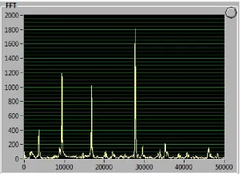
The RFDA software is then capable of passing all recorded frequencies through a
Fast Fourier Transform (FFT) and plot out the amplitude of the signals based upon the
corresponding frequencies. Figure 1.8, below, shows the FFT plot of a single recorded
impulse. The software can be set to automatically determine moduli of the material based
upon the equations defined in the ASTM 1876 standard. Prior to data collection, the
physical geometry and properties of the sample can be inputted. In addition, the method of
designated in order for the software to calculate the moduli. This is limited to simple
geometry bars of circular or rectangular cross-section and round disks. For more
complicated sample geometry, alternative equations must be used, however, are still able
to produce accurate results. Several studies were performed for this paper to validate that
these alternative equations can be used for geometries different than those mentioned in
the ASTM standards
Figure 1.8: Range of Frequencies with corresponding Amplitudes from Fast Fourier Transform
1.6 Application of Impulse Excitation
Much research has been performed on the applications of impulse excitation in
regards to the various materials tested and the various material aspects that can be analyzed.
[36,40,43,44,45] The conclusions of earliest IE research led to the standardized testing
methods such as ASTM 1875 and 1876. These standards were specified for use with
isotropic elastic materials at ambient temperatures, however, recent studies have been
Computation of theoretical transverse vibration of bars with uniform cross-sections
performed by Timoshenko and Pickett led to the experimental determination of flexural
and torsional resonant frequencies of isotropic bars. [46,47] Timoshenko was one of the
pioneers that investigated the effect of shear deformation and rotational bending on the
dynamic motion of beams of uniform cross-section under various boundary conditions
(simply supported, free, clamped, etc.). [46] In the late 1950’s, Spinner performed rigorous
experimental testing of Timoshenko’s theories and found good agreement with the results.
[48] It is from this research that the ASTM standards for the use of resonant frequency
analysis and impulse excitation are based.
With the creation of the steam turbine and other high speed machines, it became
apparent that a method for determining fatigue of the rotating components was needed.
[49] Metals were the primary material used in the high speed turbine components and were
the first types of material that vibration analysis was performed on. In 1939, Rathbone, a
plant engineer, made the observation of the displacement of certain rotating shafts at low
frequencies and correlated these to the integrity of the shaft. [50] Empirical observations
such as this would eventually lead to the experimentation performed by Spinner to validate
previous vibration theories.
As technology advanced and more complex computational tools became available,
investigation of more than a materials resonant frequency was performed. Impulse
Excitation permits the non-destructive testing of material for frequency and internal friction
(damping properties) in harsh environments that would otherwise disrupt the use of other
NDT methods. In regards to metals, IET is a common method for testing. Heritage
at elevated temperatures. [51] It was concluded that under certain configurations, wave
guides can be used to consistently deliver the vibration signal of the sample to the acoustics
microphone. These findings correlated well with mechanical testing and piezoelectric
ultrasonic composite oscillator technique testing of the pure Aluminum. Radovic
performed similar IET on aluminum and steel samples of various geometries and found
good correlation between the resulting moduli and those found by resonant ultrasonic
spectroscopy and 4 point-bending tests. [52] Swarnakar and Jung performed IET on TiB2
and structural steel, respectively, and each found damping peaks that correlated to phase
changes in the metallic microstructure. [53,54] Another study involving the damping
behavior of material structural integrity of metals was performed by Goken. It was
determined that an increase to material damping resulted from crack growth during
prolonged heat treatment in magnesium alloy. [55]
In addition to metals, polymers are an excellent material to perform IET on due to
their viscoelastic nature. [45] A viscoelastic material exhibits the characteristics of both
viscous and elastic materials in which a viscoelastic material will dissipate stored energy
during unloading in the material’s elastic stress range. As a result, polymers have become
suitable interface and matrix material for high damping composites. Finegan noted various
enhancements to composite materials that would improve damping properties. It was found
that various layering configurations of polymer interfaces in a composite yielded
reasonably high damping. In addition, it was mentioned that co-curing of embedded layers
and hybridization of laminae under various fiber orientations enhanced the loss factors of
Much study has been performed in regards to nondestructive testing of ceramics
via resonant frequency analysis and impulse excitation. [36,57] Despite having low
damping characteristics, monolithic ceramics are excellent subjects for nondestructive
testing due to their primary failure mode of micro-cracking. Ceramics tend to have high
thermal resistance and are therefore used for various high temperature applications, such
as turbine and engine structural components. As a result, non-destructive testing can be
applied to ceramic materials exposed to high temperature testing via IET. Studies
performed by Roebben greatly involved exposing ceramics to elevated temperatures and
initializing IET on the samples to validate internal defects and phase alterations. The same
Resonant Frequency and Damping Analyzer (RFDA) used in these studies was used in
experimentation performed for this work. In one of the studies, Roebben investigates the
effect of elevated temperatures on the damping characteristics of oxide (Al2O3 and ZrO2)
and non-oxide (Si3N4) ceramics. The findings indicated that little frequency and damping
changes occurred below 1000o F, however, quickly progressed at higher temperatures due
to mobility of grain boundary defects and softening of secondary material phases in Al2O3.
[36] Damping peaks were found for ZrO2 that corresponded to the thermally activated
displacement of compensating oxygen vacancies that were present throughout the materials
thermal loading. In this same paper, damping peaks were observed during the loading and
unloading cycles of the Si3N4 due to the crystallization of intergranular phase of the
non-oxide ceramic. Another study by Roebben on IET of SiC and Si3N4 ceramic samples found
that variations of the annealed composition affected the damping amplitude of material
damping peaks. [58] Bemis performed IE of thermal shocked monolithic SiC rings cut from
temperature and impulse after each heating and quenching cycle for resonant natural
frequency and damping collection. [44] After first heat cycling to 250o C, only a damping
change of 0.3 % occurred, however, a damping change of nearly 50.0% was found after
the ultimate cycle to 800oC. It was observed that visible cracking began after quenching
cycle from 400oC to room temperature. Although moduli was not determined from this
experimentation, it can be clearly seen that IET provides useful health monitoring for
thermally shocked materials prone to material cracking under rapid temperature changes.
Impulse Excitation has been of particular interest in regards to testing composite
materials. As mentioned in previous sections, damping characteristics are greatly
influenced by a materials micro-structure. [36,58] Considering that composites experience
a variety of micro-damage (micro-cracking, delamination, fiber break, etc.), this enables
IET to be an excellent method for non-destructive testing as seen from the recent research
performed. [41,42,43,59] Experimentation on glass and graphite fiber composite cantilever
(fixed-free) beams was performed by Crane, in which changes in loss factor was correlated
to changes in beam length. Crane determined that increases in beam length resulted in an
increase of loss factor and therefore the damping properties of each of the composites. [41]
A significant point behind this study was that it showed how impulse excitation testing
could be performed on a sample held in a cantilever mode of vibration and still produce
reliable results.
In a study conducted by the National Aeronautics and Space Administration
(NASA), IE on various graphite/ epoxy composites for Dynamic modulus determination
was compared with conventional mechanical testing and laminate theory. [40] This study
materials and emphasized how the method had potential for concurrent quality control. Atri
conducted IET of MMC composites for elastic modulus determination. These samples
consisted of discontinuous titanium-monobromide (TiB) whiskers of random orientation
imbedded in a Ti matrix with volume fractions ranging from 30 -83% TiB. Calculations
for moduli (Young's modulus, Shear modulus, and Poisson's Ratio) followed equations
implemented by those in ASTM standard 1876. A trend was found in which as TiB whisker
volume fraction increased, Young's and Shear moduli for the composite increases as well.
Properties calculated from IET correlated strongly with those of conventional mechanical
testing for all samples. Impulse Excitation can effectively be implemented on composite
material and can be confidently used in this paper.
1.7 IE Testing of SiC Composites:
For this study, IET will be used to both non-destructively determine elastic moduli
and monitor structural integrity via damping properties changes for SiCf-SiCm braided
composite tubing for nuclear fuel application. As mentioned, the goal is to investigate
possible applications for the testing method while conducting accurate material testing that
is comparable to the current nuclear industry. Since the 1970’s, three generations of SiC
fibers have been constructed for potential nuclear fuel use. The first two contained much
oxygen and carbon impurities, therefore densification of the fibers occurred and
mechanical properties of the SiC-SiC composite structure degraded over time when
exposed to neutron irradiation. [1] In the latest generation of SiCf-SiCm composites,
Hi-Nicalon Type S grade Silicon carbide fibers were implemented which yielded less
degradation of mechanical properties when exposed to higher temperatures and neutron
Although a fair amount of mechanical testing has been performed on SiCf-SiCm
braided composite tubing, not much non-destructive testing has arisen since the initial
development of CMC's for nuclear fuel. [3,17,18,19,20,60] The current state of the art
primarily utilizes acoustic emission to monitor the CMC braided tubing for concurrent
damage evolution and micro-structural changes. In more recent studies, micro-crack
identification has been performed using Electrical Resistance (ER) testing for ceramic
matrix composite materials. [61,62] For this procedure, an electrical current is passed
through the material and the electrical resistance is recorded. This resistance correlates to
the density of fiber and matrix cracking present in the composite material. Although both
AE and ER testing have been proven to be excellent structural monitoring methods,
impulse excitation has the capability to determine material elastic moduli in addition to
numerically quantifying correlated material damage.
Thus far, IET of SiCf-SiCm composite has been limited. Of the research that has
been performed on SiCf-SiCm composite material, studies on simple geometry of
rectangular cross-sectioned bars has been conducted. Work at Oak Ridge National
Laboratory (ORNL) determined that using the equations set in ASTM standard 1876
yielded accurate and repeatable modulus calculations for prismatic bars of SiCf-SiCm
woven composite. [63] In this study, it was found that of three samples tested, standard
deviation of the resulting Young's Modulus in the longitudinal direction of the woven
samples came within less than one percent of the average modulus taken. This low
deviation in data matches well with those found in other studies involving IET of woven
Identification of micro-cracking within CMC cladding under elevated thermal and
mechanical loading can play an important part in the design process for future nuclear fuel.
Should IET be employed as a commercial method for health monitoring of SiCf-SiCm
composite cladding, composite structures may be designed to more adequately
accommodate vibration analysis before and during use in reactor. Although not available
in this paper, fiber orientation of fiber reinforced braided tubing could be tested for
improvements to damping properties. In addition, a more in depth investigation of the
various metal matrix components could be conducted to improve mechanical failure and
damping capabilities. IET would also have some effect on the total fuel cycle in which time
for material strength analysis of cladding while in core could potentially reduce. [20]
Unlike other NDT methods, IET requires less equipment and is therefore less cumbersome.
Cost for IET equipment is also significantly less than other methods that require complex
CHAPTER 2: EXPERIMENTAL SETUP
2.1 Tension Setup
Tension testing of the SiCf-SiCm composite tubing was performed using an
ADMET eXpert 2611 universal material test machine with MTESTQuattro software to
determine the Elastic Moduli in the axial direction of the tubing. To grip the hollow,
cylindrical specimen, a set of adapters were designed and fabricated to ensure that only
axial loading would be applied to the sample during tensile testing. Composite tubes that
were meant to be tested for tensile properties had a cylindrical nut adhered to each end of
the sample. This nut will be referred to as the sample adapter nut and is compatible with
both the tension and torsion adapters that connect the sample to the mechanical rigs. To
allow co-axial alignment between the sample tube and the adapter nuts, the sample and
adapter nuts was clamped on to supportive V-blocks before adhesive curing. The center
v-block supporting the sample tube was then shimmed appropriately for alignment. Figure
2.1a and b, show details for adapter nut attachment.
Figure 2.2, shows the sample adapter nut inserted and pinned with the tension
adapter connector. The sample adapter nut is constructed using 3/4” outer diameter (OD)
Aluminum rod with an axial through hole that is slightly oversized than the OD of the
tubular sample. The axial through hole was cut to be approximately .020” larger than the
test sample. The end of the sample adapter nut was machined into the shape of a cone to
prevent any unwanted stress concentration development in the sample at the adapter nut
end. A 3/8” through hole was milled perpendicular to the adapter nut axis for a connector
pin to the adapter connector. The adapter connector, as seen by the design schematic in
Figure 2.3, is constructed from a high strength tool steel. The purpose of the connector is to
eliminate parasitic bending and to allow self-alignment during tension testing. This will
Figure 2.3: Schematic of adapter connector for tension
A similar tension test setup was used by Rohmer in tension testing of hollow SiCf
-SiCm composite tubing, as seen in Figure 2. 4. [3] Rohmer epoxied the composite tubing
ends into cylindrical aluminum tabs to adequately hold the sample along the axial direction.
Strains were read using Digital Image Correlation (DIC) of the sample and extensometers.
2.2 Torsion Setup
A torsional rig was designed and constructed for the purpose of torsion testing of
cladding tubes. As shown in Figure 2.5, the rig was built on an aluminum structural rail
with high torsional rigidity. Along the railing, two movable aluminum platforms were
rigidly bolted to the railing. At the external end of each of these platforms are shallow,
cylindrical recesses that fit circular tool steel wrench heads. Slots are cut through the
platforms to the center of the recesses to allow sample tubing to be placed between the
platforms. The lower wrench has a load cell bolted to the end which will read the force
exerted on the system during testing. The upper wrench can be attached to a motorized
actuator or operated manually. For torsion testing of material for this study, only a small
amount of torsional force is required and therefore the torsion will be delivered manually.
To conduct as many mechanical tests as possible with such a few number of tubular
samples, all tension and torsion tests will be performed to simply to determine moduli and
not ultimate stresses. Figure 2.5, below, shows the operating components of the torsion rig.
The hex shaped slots in the wrenches accommodate a 9/16” nut. As result, in lab
fabricated adaptor nuts must be created and adhered to the ends of the tubular samples to
adequately transmit force to the sample for testing. Two adapter connections were made
out of high strength steel rod of 1-1/4” diameter. A shallow, inner hole was milled to closely
fit the OD of the adapter nuts and a 3/8” pin hole was cut perpendicular to the axis of the
adapter connection to hold the adapter nut. On the opposing axial end of the adapter
connection, hexagonal studs were milled to closely fit the hex slot of the torsion wrenches.
Figure 2.6 and Figure 2.7, shows the schematic of theadapter connector for torsion and total
adapter configuration for the torsion rig, respectively.
Figure 2.7: Adapter configuration to transmit torsion to the tubular sample
2.3 Internal Pressure Setup
To induce internal pressure of the tubular sample, an updated version of the Internal
Burst Rig utilized by Alva and Shapovalov was used for pressure testing. [17,60] The
Internal Burst Rig operates by pressurizing a flexible, polymer tube (part # 5006K66 from
McMaster) with food grade hydraulic oil to expand it inside the testing sample and exert
mechanical stresses primarily in the hoop direction. A manually operated hand pump
(Model 37-6-30 from High Pressure Equipment Company) is connected via high pressure
tubing to an analog pressure gauge in addition to a digital pressure sensor (Model
PX01S1-20KGI Pressure Transducer by Omega Engineering). The analog gauge is used for visual
monitoring of the internal pressure by the operator. The high pressure metal tubing system
then leads to the polymer bladder which is connected to the sample mount. On the sample
mount are a series of brackets and telescopic adapters that hold the tubular sample with the
polymer bladder threaded through. To accommodate various sample tubing lengths, the rig
end was designed to be adjustable. In addition, a large assortment of sample adapters were
created for testing of tubing with different inner diameters. Figure 2.8 shows how an
Figure 2.8: Image of adapter supporting test sample during internal pressure test
All composite samples used in the impulse excitation study were internally
pressurized. The first sample was tested to determine mechanical properties while the
remaining composite samples were systematically loaded and unloaded. These loadings
were to increasing internal pressures while frequency and damping are recorded after every
cycle. To maintain consistency between each IE recording, the upper vibration clamp and
the lower support clamp will not be removed. Any adjustment of these two components
could affect the rigidity of the support for the tubular and thus alter the recorded vibration.
After each increase in pressure loading, the upper segment of the pressure rig, including
the telescopic and sample adapters, will be raised away from contact with the sample. The
polymer bladder will also be stretched upwards to ensure no interference with the tubular
sample's vibration motion.
The horizontal brackets serve to maintain proper alignment of the sample and to
adequately distribute any axial loading from the sample to the supports of the pressure rig.
pressure is applied to the system. In addition, the lowest horizontal bracket has through
holes near the center of them to allow bolting of the support clamps for the IE tests. Once
the composite samples are installed on the pressure rig, the support clamps are then bolted
to prepare the samples for rig mounted IE.
2.4 Mechanical Validation
2.4a Tension and Torsion
Tension testing of materials is very accurate for determining elastic moduli using
the ADMET tension tester, however, it is important to validate whether the adhering of the
adapter nuts to the sample have an impact on this testing. To prove that the desired adapter
configuration is adequate, tension testing was performed on Aluminum alloy 6061tubing
(McMaster part # 9056K64) before testing of the SiCf-SiCm composite. Aluminum 6061
is a common and inexpensive material with accurately known mechanical properties. A 6”
aluminum specimen of 1/2” OD and ¼” ID was cut and had sample adapter nuts adhered
to each end by high-strength JB Weld epoxy. Prior to installation, the adapter nut had an
axially drilled 3/8” through hole to serve as an air way when the adapter nut and sample
are adhered. A 1-1/2” deep hole of diameter slightly larger than the sample OD was drilled
to accommodate the tubular sample. Tubular specimen and adapter nuts were set in a set
of V-blocks for curing. Thin aluminum shim was used to properly align the axis of the nuts
and the specimen. This will help reduce and transverse bending that the sample may
experience during the axial loading.
After epoxy curing, two linear strain gauges were installed to the outer surface of
the aluminum sample in the axial direction. To also account for any transverse bending,
post-analysis of the tension test, the average between the strain gauges will be taken. Strain and
load readings will both be recorded via the ADMET software which will be programmed
to load to no more than 400 N of axial force at a cross-head displacement rate of .066 in.
per minute. Due to the high sensitivity of the strain gauges, low levels of force are need to
displace the sample and determine moduli. In addition, low level of axial force will be
applied during all mechanical tests to prevent any sample yielding or cracking depending
on the material.
After tension testing of the aluminum tubular specimen, validation of the torsion
rig must be achieved. Based upon design of the adapter nuts and connections, the adapter
nuts used for tension testing are compatible with the torsion rig as well. As such, the only
augmentation of the aluminum specimen that must be done is to have a shear strain gauge
installed along the axial direction. Each adapter nut can then be pinned into the adapter
connectors and then be set into the torsion wrenches. As mentioned before, torsion of the
tubular sample will be performed manually to ensure that the torque on the sample will not
damage the sample.
2.4b Internal Pressure
Validation of the internal pressure rig was performed previously by Shapovalov.
Shapovalov tested aluminum tubing and found accurate results compared to published
values. [17] The short tubes of aluminum were tested with four strain gauges attached, two
in the hoop and two in the axial directions. Shapovalov also validated uniformity of internal
pressure applied throughout the length of the sample. An aluminum tube of 304 mm had
strain gauges attached along the hoop direction of the tube at locations 50.8, 152.4, and
![Figure 1. 3 Time dependent micro-crack development. [16]](https://thumb-us.123doks.com/thumbv2/123dok_us/8392981.1385519/23.612.182.418.387.625/figure-time-dependent-micro-crack-development.webp)


![Figure 2. 4: Axial tension testing of SiCf-SiCm composite tubing with extensometers [3]](https://thumb-us.123doks.com/thumbv2/123dok_us/8392981.1385519/46.612.137.492.82.312/figure-axial-tension-testing-sicf-composite-tubing-extensometers.webp)

![Figure 2. 9: RFDA System 24 hardware used for IE testing [64]](https://thumb-us.123doks.com/thumbv2/123dok_us/8392981.1385519/54.612.140.483.191.431/figure-rfda-system-hardware-used-for-ie-testing.webp)