Article
Development of a Current Sensor with Broad Current
Measurement Range Using High- and Low-Range Parts
Jung-Won Shin1, Sae-Wan Kim1 and Shin-Won Kang1,*
1 School of Electronics Engineering, College of IT Engineering, Kyungpook National University, 1370
Sankyuk-dong, Bukgu, Daegu, Republic of Korea; [email protected]; [email protected]
* Correspondence: [email protected]; Tel.: +82-53-950-6829 (S.K.)
Abstract: The measurement range of a conventional current sensor is narrow because it is used with signals relative to the rated values of the measurement range from a voltage-type device. Consequently, multiple current sensors must be used in accordance with the measurement range. To address this problem, this paper proposes a new current sensor with a clamp-shaped part for low current measurement and a simple straight structure for high current measurement. The output signals of the proposed current sensor are amplified with a Hall element using the magnetic force of a rectangular air gap inside the clamp. To verify the characteristics of the proposed current sensor, a current was applied to an external load, and the value determined by the current sensor noted. Then, electromagnetic field analysis was performed through current sensor modeling and the results obtained compared to the actual sensor results. The proposed sensor had a 1% linearity in the output signals and exhibited dynamic characteristics over a wide current range.
Keywords: Current sensor; Hall effect; Hall IC; Rogowski coil; Current transformer
1. Introduction
In the future, utilization of alternative energies derived from nature is expected to increase along with the power consumption of machines. The demand for control and protection technologies to monitor the current usage of systems, equipment, and robots in preventive diagnosis, management, operation, and service industry applications will also increase. Thus, components that can accurately measure currents are required [1]–[3]. For current measurement, electrical shunts, Rogowski coils, Current transformer and current sensors are the primary components used. However, with these components, the rated range must be defined. The product volume thus increases as the amount of current to be measured increases.
Shunts can become overly voluminous and difficult to utilize when the measurement range is large [4]. Rogowski coils are advantageous in this area because they use an air core or nonmagnetic materials. Thus, they are not magnetically saturated and can measure a broad range of currents. However, the current frequencies are limited by the impedance characteristics, and the voltage induced in the coil is low when a low current is being measured. When measuring low current, a low voltage is less abandoned in the coil, and for a continuous fine vibration, and in the case of moving machinery, the coil position is changed, resulting in an error rate [5–7]. The current transformer is cheap and easy to use; however, it can only measure the ac area.
The current sensors that have been developed to date can measure both AC and DC and have a wide frequency range and high reliability. However, the measurement ranges of the current sensors are
measurement range. Each sensor can generally measure up to 1.5 to three times the rated current; however, multiple current sensors must be used for accurate measurement [8]–[10]. this is because a sensor rated for a particular range cannot measure a wider or higher range of values owing to its position in the module, saturation due to limitations of the core material, and magnitude of the air gap. One current sensor does not measure a wide area. [11].
To measure a current of 100 A, the typical circular sensor diameter size must be 5–30 mm for a circular shaped sensor and 10×10 to 30×30 mm for rectangular sensors. Thus, an externally mounted sensor cannot adequately measure the of 100 A of a large bus bar. It is difficult to mount the current sensor presented here on large bus bars owing to the small inner space. In contrast, to measure 10 kA or higher currents using large-capacity current sensors, even with wide measurement ranges, the measurement accuracy for low currents is low. Thus, verifying the linear outputs of 0.1 kA current signals using 10 kA sensors is difficult.
In this study, a current sensor using a Hall element or a Hall IC was developed for system devices and modules that require measuring high currents in real time. The developed sensor has a simpler and smaller structure than shunts. Furthermore, it has a wide current range.
Considering the disadvantages of existing current sensors mounted on system devices that cannot be used in large bus bars owing to small volumes, a clamp-type structure design for low currents is also proposed herein. For high current measurements, a simple straight ferromagnetic sensor is attached to the instrument. Whereas existing studies have only used the principle of density of magnetic flux from one air gap, in the present work, an air gap is created with a simple straight current sensor, and a wide dynamic range current sensor that uses the surrounding magnetic field by adjusting the air-gap length is proposed.
2. Hall Effect
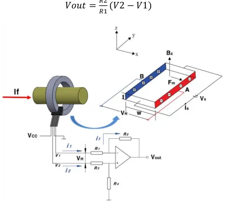
As shown in Fig. 1, when current flows through the wires in the magnetic field, a potential difference occurs of the current flow at right angle in the direction. The direction of motion of the electron in a perpendicular direction is the direction of the y-axis. The electrons moving in the x-axis direction are affected by the z-axis direction. The current causes a vertical magnetic field in the semiconductor from left to right. The former is driven to the side of the force. Measurement of the potential difference between the current and the two ends of the plane perpendicular to the magnetic field gives rise to the hall voltage. Applying voltage(V) to a semiconductor with length w and thickness t, causes the current (I) to flow in x direction, the magnetic field is produced in the direction of Bz , resulting in the charge being disposed
of in plane A and plane B in the direction of force(Fm). The current and the magnet have a
voltage(VH)perpendicular to it.[12],[13]. The Hall electromotive force (VH) is defined as follows:
𝑉𝐻 = 𝐾𝐻 ∙𝐼𝐶 ∙ = ∙𝐼∙ (𝐵/𝑑), (1)
where 𝐾𝐻is a proportional coefficient and is also called product sensitivity, 𝑅𝐻is the Hall coefficient, d is the element thickness, 𝐼𝐶is the control current of the Hall effect sensor with a standard value of 1 mA, and B is the magnetic flux density. In Fig. 1, the Hall effect sensor, which is a major part of the current sensor, measures the magnitude of a magnetic field. It’s output voltage is directly proportional to the magnetic field strength through it. [12],[13].
2.1. Open loop Current Sensor using a Hall effect sensor
material, and the Hall voltage is amplified by the opamp. The output signal of the Hall effect sensor consists of a differential amplifier. Open loop with a compensation circuit that guarantees zero offset value to reduce output signal deviation of hall effect sensor. [14],[15] With the fine mV signal of the Hall effect element, the input current i2 is transmitted to ground by the high input impedance of the differential amplifier. The input current i1 is transmitted to the output end as it is by the high impedance of the differential amplifier. Expression is defined as follows:
𝑉𝑜𝑢𝑡 =𝑅2
𝑅1(𝑉2 − 𝑉1) (2)
Figure 1. Operating principle of a current sensor with a Hall effect sensor.
2.2. Proposed Current Sensor
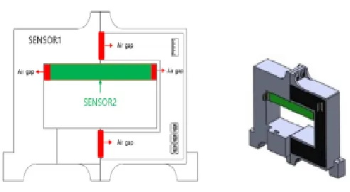
The proposed wide range current sensor (Fig. 2) measures low currents with Sensor1 and high currents with Sensor2. Sensor1 has an external diameter of 160x119x32mm, an internal diameter of 105x45x32mm and a sensor2 of 105x10x32mm.The volumes of these two sensors (Sensor1 and Sensor2) contrast with those of conventional sensors. More specifically, Sensor1 has a large volume but measures low currents, and Sensor2 has a small volume but measures high currents. For this sensor, the space utilization has been improved, and the measurement range of the rated current values can be extended by the air-gap length. A straight current sensor is inserted inside the rectangular inner space.
Fig. 2(a) shows that 3-mm wide upper and lower air gaps were designed for Sensor1 and 6.5-mm wide left and right air gaps were designed for Sensor2. The conditions are changed to perform different experiments. For measurement of a high current of 10 kA with Sensor1, 20-mm upper and lower air gaps are used to calculate the magnetic flux density, and for Sensor2, the same 6.5-mm air gaps are used. For Sensor1, a noryl case (Hankook Sensor Co., Ltd.) was used and Sensor2 was produced by Laminaring 3D printing. Sensor1 and Sensor2 were fixed using tape. Power is supplied to the PCBs through a Molex 5045 pin for Sensor1 and a 5-pin for Sensor2. The sensed current value is received as a voltage-type output.
(a) Positions of air gap containing sensor1 and air gap containing sensor2 (b) 3D model of the proposed sensor
(c) Schematic of fabricated sensor system.
Figure 2. Proposed wide dynamic range current sensor
3. Experimental Evaluation
3.1. Load experiement method
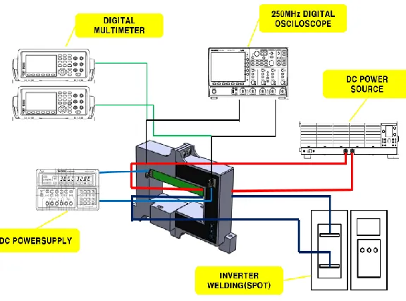
The following experiment was performed to quantify the performance of the proposed current sensor. For power supply, a DC current supplier (KIKUSUI Rated 0–160 A, CC : Load Regulation 0.1%+10 mA, CV : Load regulation
0.05%+5 mA) that supplies sensor power and applies conductor current for measurement was used. The current
was divided 11 times for stable supply, and the output current values of Sensor1 and Sensor2 were measured with two digital multimeters. Owing to the difference in the capacity of the secondary load test device, the 10 kA device (Top Engineering Load output current 30 kA Operating Frequency 1 kHz) was measured with a different DC power load while increasing from 4 kA in 1 kA increments.
Figure 3. Load measuring systems for the wide range current sensor
3.2. Simulation of hall current sensor with electromagnetic field..
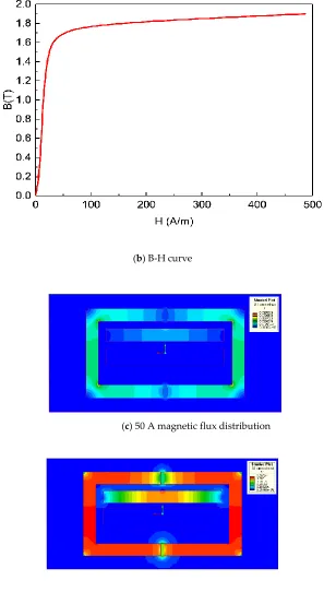
To verify the reliability of the experiments for the proposed current sensor, the model shape was divided into a mesh considering the nonlinear characteristics of the silicon steel core material by using the finite element method with the 3D electromagnetic field phenomenon, as illustrated in Fig. 4. Then, thermal analysis was conducted based on the magnetic flux density calculation position and the current distribution of a 23ph095 silicon steel plate BH-date. The core heights and air gaps of the Sensor1 and Sensor2 models were not changed. The results demonstrated that the magnetic flux density distribution changed according to the current variation. These changes are described in detail in the following section.
(b) B-H curve
(c) 50 A magnetic flux distribution
(d) 5.0 kA magnetic flux distribution
Figure 4. Electromagnetic field shape and magnetic flux distribution of the proposed wide dynamic Hall current sensor.
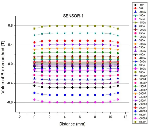
of the model, and dividing the self-sufficiency distribution by 50A to 5kA. Fig. 4.(c) (d) magnetic flux distribution can be seen. It can be seen that high current can be measured by shading. The difference in self-speed distribution in low and high current is much greater, depending on the sensor1 and sensor2 core shading values when current is 50A and sensor1 and snesor2 when current is 5kA. Optimized designs for the rated current value of the sensor can be made with respect to the analysis of the magnetic flux distribution. Fig. 5(a) (b) shows the best magnetic flux density when the highest magnetic flux density position of the air gap is in the middle, depending on the distance between sensor1 and sensor2. Fig. 6(b) shows the air gap position of sensor1. Fig. 6(a) and 6(c) show the magnetic flux density graph for the air gap above and below sensor1, respectively. Figure 6(d) The graph was tested with the upper and lower air gap of Sensor1. For black, sensor 1 has the same upper and lower air gap. The red has a different air gap in sensor1.The graph in Fig. 6(e) shows that the air gap of sensor1 of the proposed sensor is changed; however, for sensor2, it does not change. Because the overall magnetic flux density value of the air gap of sensor1 changes, the linearity of sensor2 is affected. according to the color changed around the core is red as the magnetic flux distribution around the core increases. The optimized value can be obtained by comparing the calculated values of magnetic flux density. The optimized analysis values of the electromagnetic fieldanalysis suggest that an optimized and stabilized sensor core design can be obtained with 4–5 kA.
The core material of the proposed sensor was double grain-oriented silicon steel. It was made by using winding direction steel, and it was interpreted one way because of its sensitive to core investment and wide air gap.
(b) Density of magnetic flux according to air gap of sensor2
Figure 5.Density of magnetic flux according to air gap distance of sensor
(a) Graph of magnetic flux density according to the distance of the upper air gap of sensor1
Sensor 1 lower air gap graph
(b) Air gap position of sensor1
(d) Air gap comparison graph for sensor1
(e) Air gap comparison graph for sensor2
Figure 6.Comparison by Air Gap Change.
4. Results
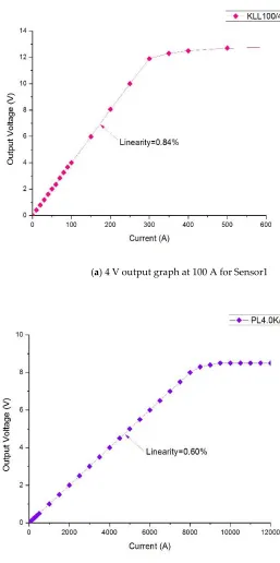
(a) 4 V output graph at 100 A for Sensor1
(b) 4 V output graph at 4.0 kA for Sensor2
Figure 7. Voltage–Current graphs of Experiment 1.
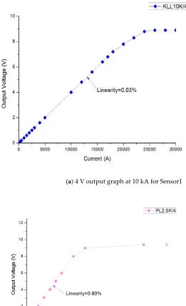
(a) 4 V output graph at 10 kA for Sensor1
(b) 4 V output graph at 2.0 kA for Sensor2
Figure 8. Voltage–Current graphs of Experiment 2.
Fig. 8(a) depicts the results of experiment 2, where the rated values of Sensor1 and Sensor2 are opposite to those in experiment 1. About 10 kA was measured with the large volume of Sensor1, and 2 kA was measured with a small volume of Sensor2, as shown in Fig. 8(b). The first experiment was conducted with a power source at one place; however, in the second experiment, although the product is the same as that in Fig. 3(b), a load current source with a 2-step energizing function of an inverter welder was used to apply a 10 kA load. For the 2 kA, the same load as in the first experiment was used. The same load could not be used because the power source of the inverter welder cannot indicate a power load less than 3 kA. The rating range was set differently.
of the output signals in comparison with the rated value, and the results for the saturated region in comparison with the rated value were verified. The results of these two experiments were not different, but the saturation relative to the rated value exhibited a difference of 1.2–3 times. The linearity of less than 1% indicated good wide dynamic range current sensor values.
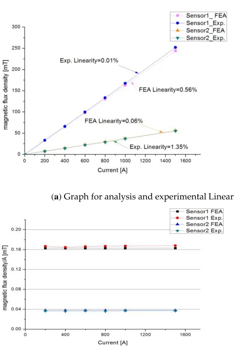
4.2. I-T Linearity
(a) Graph for analysis and experimental Linearity
(b) Graph for analysis and experimental values magnetic flux
Figure 9.Linearity and magnetic flux density of experimental and analysis values .
Graph is a comparison of load experimentation of the Holder with the value of the electromagnetic
analysis experiment. Current measured between 0 ~1.5 kA. Fig. 9.(a) The linearity of load experiment values and simulated values of Hall effect sensors can be verified. Fig.9.(b) divided the magnetic flux density per ampere of the measured values. It can be seen that the same magnetic flux is maintained.
5. Conclusion
B-H date.
Author Contributions: conceptualization, investigation, and writing, J. W. Shin and S. W. Kang; editing, visualization, S. W. Kim; formal analysis, writing-original draft preparation.
Funding:This research received no external funding
Acknowledgments: Thanks to professor Shin-Won Kang for guiding the paper preparation and thank Sae-Wan Kim of for doing experiment and helping us finish the paper.
Conflicts of Interest: The authors declare no conflict of interest.
References
1.Bodkhe, S.B.; Aware, M.V. Robust method for stator current reconstruction from DC link in a sensorless induction motor drive. Int. J. Eng. Sci. Technol. 2010 2, pp. 87–99.
2.Nagalaxmil, P.; Chary, M.V. Efficient energy management system with solar energy. Int. J. Modern Eng. Res. 2013
3, pp. 2836–2839. DOI: 10.7305/automatika.2015.12.716.
3. Kah, P.; Shrestha, M.; Hiltunen, E.; Martikaininen, J. Robotic arc welding sensors and programming in industrial applications. Int. J. Mech. Mater. Eng., 2015 10, p. 13. DOI: 10.1186/s40712-015-0042-y.
4.Lee, W.C.; Hyun, D.S.; Lee, T.K. Comparison of single-sensor current control in the DC link for three-phase voltage-source PWM converters. IEEE Trans. Ind. Electron. 2001 48, pp. 491–505. DOI: 10.1109/41.925576
5.Tsukuda, M.; Koga, M.; Nakashima, K.; Omura, I. Micro PCB Rogowski coil for current monitoring and protection of high voltage power modules. Microelectron. Reliab. 2016 64, pp. 479–483. DOI: https://doi.org/10.1016/j.microrel.2016.07.011.
6.Samimi, M.H.; Mahari, A.; Farahnakian, M.A.; Mohseni, H. The Rogowski coil principles and applications: A review. IEEE Sensors J. 2015 15, pp. 651–658. DOI: 10.1109/JSEN.2014.2362940.
7.Poncelas, O.; Rosero, J.A.; Cusido, J.; Ortega, J.A.; Romeral, L. Moter fault detection using a Rogowski sensor without an integrator. IEE Trans. Ind. Electron. 2009 56, pp. 4062–4070. DOI: 10.1109/TIE.2009.2025715.
8.So, E.; Ren, S.; Bennett, D.A. High-current high-precision openable- core AC and AC/DC current transformers. IEEE
Trans. Instrum. Meas. 1993 42, pp. 571–576. DOI: 10.1109/19.278628.
9.Lee, D.C.; Lim, D.S. AC voltage and current sensorless control of three-phase PWM rectifiers. IEEE Trans.
Power Electron. 2002 17, pp. 883–890. DOI: 10.1109/TPEL.2002.805592.
10. Gan, C.; Wu, J.; Hu, Y.; Yang, S.; Cao, W.; Kirtley, J.L. Online sensorless position estimation for switched
reluctance motors using one current sensor. IEEE Trans. Power Electron. 2016 31, pp. 7248–7263. DOI: 10.1109/TPEL.2015.2505706.
11. Dalessandro, L.; Karrer, N.; Kolar, J.W. High-performance planar isolated current sensor for power electronics applications. IEEE Trans Power Electron. 2007 22, pp. 1682–1692. DOI: 10.1109/TPEL.2007.904198.
12. Shin, J.W.; Choi, B.S.; Ha, Y.H. Improved linearity and saturation of current sensor by laminating silicon steel and fermalloy. J. Sensor Sci. Technol. 2015 24, pp. 194–220. DOI: https://doi.org/10.5369/JSST.2015.24.3.194.
13. Lenz, J.; Edelstein, A.S. Magnetic sensors and their applications. IEEE Sensors J. 20066, pp. 631–649. DOI: 10.1109/JSEN.2006.874493.
14. Ali, A.A.; Yanling, G.; Zifan, C. Study of Hall effect sensor and variety of temperature related sensitivity. J. Eng. Technol. Sci. 2017 49,pp. 308–321. DOI:10.5614/j.eng.technol.sci.2017.49.3.2.