A Low Power 32-Bit Ripple Carry Adder Using
Dynamic DML CMOS Logic Gates
R.Vijay 1& M. Damodhar rao2
1
PG student, Gudlavalleru Engg College, A.P, INDIA. 2Asst.professor, Gudlavalleru Engg College, A.P, INDIA.
Abstract:-
Now a day’s low power consumption plays a vital role in microelectronics. So in terms of power consumption we designed a low power 32-bit ripple carry adder by using dynamic DML
CMOS logic gates. Here the 32-bit ripple carry
adder previously designed by static CMOS logic gates. In static CMOS logic gates required ‘2n’ gates for ‘n’ variables, where as in dynamic CMOS logic gates require’ n+2’ gates require for ‘n’ variables. So the power consumption in dynamic DML CMOS gates is almost half of the static DML CMOS logic gates. Here, the 32-bit static CMOS ripple adder consumes an 8mw and 32-bit dynamic CMOS full adder consumes a 6.80E-1 mw.This simulations results done by Pspice simulation tool.
Keywords: static CMOS; dynamic CMOS; DML (dual mode logic); Full adder; 32-bit ripple carry adder.
I.INTRODUCTION
The present modern world has been widely using CMOS as the best logic design concept. Ultralow voltage operation, which features low-to moderate performance with ultralow power dissipation, was analyzed for the first time in 1972. Low throughput applications such as, biomedical devices, wrist watches, mobile phones and sensors makes use of this concept. In integrated circuit design, dynamic logic (or sometimes clocked logic) is a design
methodology in combinatory logic circuits, particularly those implemented in MOS technology. It is illustrious from the so called static logic by exploiting temporary storage of information in stray and gate capacitances. [1] It has been popular since 1970s and has seen a recent renaissance in the design of high speed digital electronics, particularly computer CPUs. Dynamic logic circuits are generally faster than static counterparts, and necessitate less surface area, but are more difficult to design. Dynamic logic has a higher toggle rate than static logic[2] but the capacitive loads being toggled are smaller[3] so the overall power consumption of dynamic logic may or may not be higher depending on different tradeoffs. When referring to a meticulous logic family, the dynamic adjective frequently suffices to differentiate the design technique, e.g. dynamic CMOS [4] or
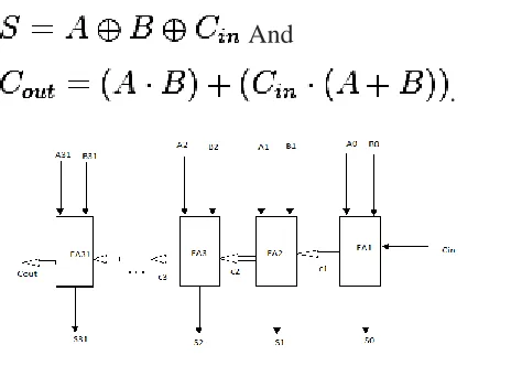
Figure (a): Transistor circuit diagram of full adder
The addition of two binary numbers and financial records for values agreed in addition to out is called full adder.
INPUT BIT FOR NUMBE R A INPUT BIT FOR NUMBE R B INPUT BIT FOR NUMBE R CIN SUM BIT OUTPU T S CARRY BIT OUTPU T COUT 0 0 0 0 1 1 1 1 0 0 1 1 0 0 1 1 0 1 0 1 0 1 0 1 0 1 1 0 1 0 0 1 0 0 0 1 0 1 1 1
Table (a): Truth table of full adder
A one-bit full adder adds three one-bit numbers, often written as A, B, and Cin; A and B are the operands, and Cin is a bit carried in from the earlier less important stage.[2] The full adder is usually a component in a cascade of adders, which adds 8, 16, 32, etc. bit binary numbers. The circuit produces a two-bit output, output carry and sum characteristically represented by the signals Cout and S, where.
Sum=2 Cout S
A full adder can be implemented in many different ways such as with a custom transistor-level circuit or composed of other gates.
And
.
Figure (b): Block diagram of 32-bit ripple carry adder
It is possible to create a logical circuit using multiple full adders to add N-bit numbers. Each full adder inputs a Cin, which is the Cout of the
previous adder. This kind of adder is called a ripple-carry adder.
adder requires three levels of logic. In a 32-bit ripple-carry adder, there are 32 full adders, so the critical path (worst case) delay is 3 (from input to carry in first adder) + 31 * 2 (for carry propagation in later adders) = 65 gate delays.
DML gates achieve very low power dissipation in static mode operation, with some degradation in performance, as compared with standard CMOS.
Figure(c): Type A and Type B modes
On the other hand, DML gates achieve very high speed in dynamic operation at the outlay of increased power dissipation. A basic DML gate is composed of any static logic family gate, which can be a conventional CMOS gate, and an additional transistor. DML gates have a very simple and intuitive structure, the novel dual mode logic (DML), which provides the designer with a very high level of flexibility. It allows on-the-fly switching between two modes of operation: 1) static and 2) dynamic modes. In the static mode, DML gates achieve very low power dissipation, as compared with standard CMOS. The proposed 32-bit full adder designed by using dynamic CMOS logic gates because it Requires „n+2‟transistors for, n, variables. The efficiency
of the developed method is shown by a comparison of the theoretical results, achieved using the proposed method with simulation results of Pspice tool.
Unit I explain about the introduction of the paper. Unit II revels the DML logic gates in static and dynamic modes and operation of DML in nand, nor, not, or, and gates. Unit III explains about results of 32 bit adder using DML.Unit IV refers the results and discussions. Unit V concludes the conclusion of the paper.
II.32-bit Full adder using static CMOS logic gates of DML:
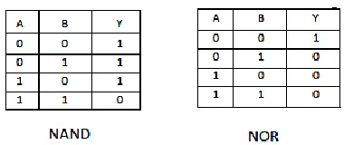
As an example, consider the static logic implementation of a CMOS NAND gate. This circuit implements the logic function. If A and B are both high, the output will be pulled low. Where as if either A or Bare low, the output will be pulled high. At all times, the output is pulled either low or high.
Table (b): Truth tables of Nand and NOR gates
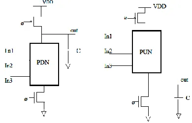
Figure (d): the CMOS transistor diagrams of Nand and Nor gates
Figure (e): Nor gate using DML Logic
When designing with DML gates is to cascade connects Type A and Type B gates, exactly like in np-CMOS gates. Even though this design methodology will allow maximum performance, minimize area, and make best use of power efficiency, it is possible to connect gates of the same type by using an inverter buffering between them, in a similar way it is done in domino logic. Connecting gates of the same type without inverters is also possible when a footer/header is used at each stage, however, this structure will
cause glitching after precharge ends and until the estimation data ripples through the chain.
Here, the 32-bit ripple carry adder designed using static CMOS logic gates of DML gates .the power consumption is 8.43E mw.
III.32-bit Full adder using dynamic CMOS logic gates of DML:
Dynamic logic is distinguished from so called
static logic in that dynamic logic uses a clock
signal in its implementation of combinational logic circuits. The usual use of a clock signal is to synchronize transitions in sequential logic circuits. For most implementations of combinational logic, a clock signal is not even needed. The dynamic logic circuit requires two phases. The first phase, when Clock is low, is called the setup phase or the precharge phase and the second phase, when Clock is high, is called
the evaluation phase. In the setup phase, the
output is driven high completely (no matter the values of the inputs A and B). The capacitor, which represents the load capacitance of this gate, becomes charged. Because the transistor at the bottom is turned off, it is impossible for the output to be driven low during this phase.
During the evaluation phase, Clock is high. If A
and B are also high, the output will be pulled low. Otherwise, the output stays high (due to the load capacitance). Dynamic logic has a few potential problems that static logic does not. If the clock speed is too slow, the output will decay too quickly to be of use. The output is only valid for part of each clock cycle. So the device connected to it must sample it synchronously during the time that it is valid.
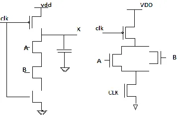
Figure (g): Dynamic CMOS Nor and Nand gates
The dynamic DML 32-bit ripple carry adder using just „n+2‟transistors for achieving of its functionality i.e. Sum and carry. This gate of logic requires power consumption is 6.80E-1 mw.
IV. RESULTS AND DISCUSSION
The largest difference between static and dynamic logic is that in dynamic logic, a clock signal is used to evaluate combinational logic. However, to truly comprehend the importance of this distinction, the reader will need some background on static logic.
Dynamic logic requires a minimum clock rate fast enough that the output state of each dynamic gate is used or refreshed before the charge in the output capacitance leaks out enough to cause the digital state of the output to change, during the part of the clock cycle that the output is not driven.
Table (c): comparison table of static and
dynamic DML 32-bit RCA
So according from comparison table, the power consumption very low in dynamic DML ripple carry adder than the static DML ripple carry adder.
Fig (h): simulation waveform of 32-bir RCA
CONCLUSION:
In this brief, we presented a novel family, DML, which was shown for 32-bit full adder operation. We showed that the DML dynamic mode presented an average speed improvement as compared to CMOS, and improved robustness as compared to a standard dynamic logic. Dynamic CMOS logic gates requires less number of gates than the static CMOS logic gates.so power consumption and delay very less than the static CMOS gates.so the 32-bit ripple carry adder using dynamic DML logic is more efficient than static CMOS DML logic gates.
REFERENCES
[1] A.Kaizerman, S.Fisher, and A.Fish, ``Subthreshold Dual Mode Logic,”IEEE Trans. Very Large Scale Integer. (VLSI) Syst., vol.21, no.5, pp. 979_983, May2013.
[2] ItamarLevi, Alexander Fish “DualMode Logic Design for Energy Efficiency and High Performance” Received April21, 2013, acceptedMay2,2013,date of publication May15,2013, date of current version May 21, 2013. 2169-35362013 IEEE.
[3]H. Soeleman, K. Roy, and B. Paul, “Sub-domino logic: Ultralow power dynamic sub-threshold digital logic,” in Proc. 14th Int. Conf.
VLSIDesign, 2001, pp. 211–214.
[4] Rajneesh Sharma, ShekharVerma, “Comparative Analysis of Static and Dynamic CMOS Logic Design” 5th IEEE International Conference on Advanced Computing & Communication Technologies [ICACCT-2011] ISBN 81-87885-03-3.
[5].G.S.Tripathi, Shiv Prakash Arya, Rajan Mishra, “Study of performance of Adiabatic Carry Look Ahead Adder Using Dynamic CMOS Logic” International Journal of Electrical
and Electronics
Engineering(IJEEE),ISSN(PRINT):2231–5284, Volume-I, Issue-II,2011.