Comparative Analysis of Real Time Discrete
PID Controller Design using First Principles
and Data Driven Model
B.Udaya Kumar1, Dr. M.Ramesh Patnaik2Associate Professor, Dept. of EIE, GITAM University, Andhra Pradesh, India1
Assistant Professor, Dept. of Instrument Technology, GITAM University, Andhra Pradesh, India2
ABSTRACT: This paper deals with the speed control of DC motor with PID controller using two different modelling approaches, viz. first principles modelling and data driven modelling. The objective is to compare the time response analysis of the motor in both the models, first by simulation as well as by a practical implementation at different speeds. This paper outlines the detailed procedure of modelling, design of a PID controller and implementation with hardware. The comparison of results show that the data driven model has a better performance compared to first principles modelling.
KEYWORDS: PMDC, PWM, MATLAB, Arduino, PID.
I. INTRODUCTION
Actuators play an important role in any control system. It serves as a final control element changes in accordance with the signal transmitted by the controller. DC motor is one of the important actuators being widely used in applications such as process control, robotics, avionics, rolling mills and automobiles etc. Several conventional and non- conventional techniques are currently in use to control the speed of a DC motor [1]. This paper presents the speed control of PMDC motor by using conventional PID controller with PWM technique. Theoretical and practical DC motor models were designed using Matlab software. With Arduino mega 2560 hardware, a practical discrete PID controller has been designed, implemented and tested for the speed control of PMDC motor. The Practical values are almost matched with the theoretical ones. A PMDC motor converts electrical energy into mechanical energy by applying the voltage to drive either linear or rotational loads. The model of the system is estimated either by first principles modelling or by data driven modelling [2][3]. In this paper both the models have been designed, analysed and presented.
PID controllers have been widely used in many process controls over 50 years and gaining its popularity. Comparison of different conventional and nonconventional techniques’ to control the speed control of a DC motor was presented by Ermira Buzi and Petraq Marango in 2013.PID controller as a conventional and inverse neural networks as a non conventional technique was presented to improve the system dynamics[1]. Villagra, Blas Vinagre, In´es Tejado developed data driven fractional PID control for the control of DC motor [2]. Pravallika Vinnakota from Mathworks presented an article on use of data driven model for position control of DC servo motor[5]. In this paper the design and implementation of PID controller in real time for DC motor speed control is presented and a comparison of its time response characteristics such as rise time and settling time are outlined.
II. FIRST PRINCIPLES MODELING
The generalized mathematical model for a DC motor to obtain the transfer function is as shown in Fig.1 and the governing equations are listed below.
V. RESULT AND DISCUSSION
Fig.1 Equivalent Circuit of a DC motor model
( ) = ( ) + ( )+ ( ) (1)
( ) = ( ) (2)
= . ( ) (3)
( ) = . ( )+ . ( ) (4)
( )
( )= . ( . . ). ( . . ). (5)
( )
( )= . ( . . ). ( . . ). (6)
( ) = ( ) (7)
Where
R = armature resistance (Ω- ohm).
L = armature inductance (H-Henry).
I = armature current (A).
V(t) = armature voltage (V).
E = back emf (V).
ω = angular speed (rad/s).
T = motor torque (N m).
θ = angular position of rotor shaft (rad).
J = rotor inertia (kg.m )
B = viscous friction coefficient (N .S/rad).
K = motor torque constant (Nm/A).
K = back emf constant (V S/rad).
Fig.2 Simscape model of DC motor in Matlab
Fig.3 DC motor electrical and mechanical parameters
III. DATA DRIVEN MODELING
Data driven approach model is an alternative to derive the model from the measured input and output data. Linear and non linear transfer functions can be estimated by the use of Matlab system identification tools.Fig.4, 5 shows the estimated linear transfer function from the acquired input output data of the PMDC motor.
The estimated linear transfer function is
= .
. . (8)
Fig.4 Estimation of linear model using System Identification Toolbox Fig.5 Linear Transfer Function
Fig.6 Estimation of Non-linear model from system identification toolbox and its data sets. The estimated Non-linear transfer function is
= . . .
. . (9)
IV.DESIGN OF PID CONTROLLER
Fig.7 shows the generalized block diagram of a closed loop feedback control system. The controller takes the error as an input signal and produces the output signal based on the type of the controller. The error signal is the difference between the set point and the measured value. The type of controller can be conventional PID or Non-conventional controllers such as fuzzy, neural or neuro-fuzzy controllers etc [6]. PID controller is the most generally used feedback controller widely adopted to control any process due to its simplicity. The controller generates the manipulated variable based on the present, past and future error through proportional, integral and derivative terms.
Where,
u(t) = Controlleroutput K = Proportionalconstatnt K = Integralconstatnt K = Derivativeconstant e(t) = Errorsignal
Fig.7. Block Diagram of feedback Control system
Implementing a PID or other dynamic compensators requires skills in digital control, programming and the support of advanced processors [7].The main disadvantage of the PID is tuning of the PID parameters. Tuning of the PID controller is done either offline or online. Different offline tuning techniques such as Ziegler Nicholas and open reaction curve method exists in literature [8]. This paper illustrates the tuning of PID in offline with Matlab automatic tuning tool kit [9][11].
Fig.8 General Matlab Simulink model
Fig.9. Tuned PID step response and its parameters of first principles model The above procedure is repeated for the data driven linear and non linear models as shown in Fig.10, 11.
Fig.10 Tuned PID step response and its parameters of data driven linear model
Table 1 shows the comparison of tuned values of PID parameters obtained.
Table1. PID parameters of first principles and data driven models, rise time, settling times
Simscape Model Linear Model Non-Linear Model
P 1.664 0.00035999 0.04148351828
I 1.287 0.071998 0.12313
D -0.26 0 0
Rise Time (Sec) 1.84 2.13 1.51
Settling Time (Sec) 6.65 3.82 2.7
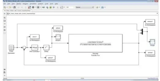
Fig.12. shows the Simulink model with linear transfer function to simulate the motor speed at 2500rpm square stimulus to analyse the time response characteristics.
Fig.12 Closed loop PID control Simulink model with DC motor linear transfer function
Fig.13. shows the Simulink model with linear model to simulate the motor speed at 2500rpm square stimulus to analyse the time response characteristics.
Fig.13 Closed loop PID control Simulink model with DC motor Non-linear transfer function
Fig.14 Real time closed loop PID control Simulink model
The DC motor is tested for various speeds and the theoretical and practical values are satisfactory.
IV. HARDWARE SET UP
The data required for the data driven model is collected by using Arduino Mega 2560 microcontroller and L293D H-bridge driver with PWM control technique. Fig.14 shows the block diagram of hardware set up for data acquisition
Fig.15 Block diagram of speed control of dc motor
The sensitivity of the DC motor is 1.9V/1000 rpm. At 4500 rpm the output voltage from the motor is 8.5V.However the microcontroller accepts the maximum analog input voltage of 0 to 5v.A level shifter is designed to reduce the voltage of 0 to 8.5v to 0 to 5v range. To remove noise from the output of the tachometer a RC filter has been designed. The voltage is measured with Arduino Mega 2560 board with a sampling rate of 0.001 sec and converted into speed.PID controller takes the error as an input and generates the PWM duty cycle accordingly.
The DC motor is controlled using L293D H-bridge controller. Pin numbers 6, 13 of the Arduino board are used to generate the PWM signal and are interfaced to the control inputs 1A and 2A of the H-bridge controller. The motor is connected in between the output pins 1Y and 2Y of the driver. The speed of the motor is proportional to PWM signal. The motor has in built tachometer that generates the voltage proportional to its speed. The output of the tachometer is given to the DC level shifter through an RC filter. The signal from DC level shifter is given to analog input A0 of Arduino board.
Fig.16 Circuit diagram of the DC motor speed control
Fig.17 Experimental Setup
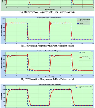
VI. RESULTS AND DISCUSSIONS
Fig. 18 Theoretical Response with First Principles model
Fig. 19 Practical Response with First Principles model
Fig. 20 Theoretical Response with Data Driven model
V.CONCLUSIONS
The Speed of the DC motor has been controlled with PWM technique. The theoretical model has been designed and simulated .The simulation results are validated practically by Arduino hardware and results are matched satisfactorily. As the model becomes complex a non conventional techniques such as hybrid models such neuro fuzzy, genetic algorithms or adaptive predictive control techniques can be preferred as a future scope.
REFERENCES
[1] Ermira Buzi, Petraq Marango, “A comparison of conventional and nonconventional methods of DC motor speed control”, 15th IFAC Workshop on International Stability, Technology and Culture, Vol. 46, no. 8, pp. 50-53, June 6-8, 2013.
[2] L. Petru, G. Mazen, “PWM Control of a DC Motor Used to Drive a Conveyor Belt”, Procedia Engineering”, Vol. 100, pp. 299-304, 2015. =
[3] Jorge Villagra, Blas Vinagre , In´es Tejado, “Data-driven fractional PID control: application to DC motors in flexible joints”, IFAC Conference on Advances in PID Control PID'12 Brescia (Italy), Vol. 45, no. 3, pp. 709-714, 2012.
[4] http://www.mathworks.com/academia/arduino-software/arduino-simulink.html.
[5] https://in.mathworks.com/company/newsletters/articles/motor-control-with-arduino-a-case-study-in-data-driven-modeling-and-control-design.html?s_tid=srchtitle.
[6] E. Gowthaman, C.Dinesh Balaji, “Self Tuned PID Based Speed Control of PMDC Drive”, Electrical Review, Vol. 88, no.6, pp. 686-692, 2012.
[7] T. O..Mahony, C J Downing and K Fatla, “Genetic Algorithm for PID Parameter Optimization: Minimizing Error Criteria”, Process Control and Instrumentation 2000, pp. 148- 153, 26-28 July 2000.
[8] P. Pillay and R. Krishnan, “Modeling, Simulation and Analysis of Permanent-Magnet Motor Drives Part I: the Permanent-Magnet Motor Drive”, IEEE Trans. on Industry Applications, Vol. 25, no. 2, pp. 265- 273, 1989.
[9] Bennett S, “Development of the PID controller”, IEEE Control System Magazine, Vol. 13, no. 6, pp. 58–65, 1993.
[10] D. Puangdownreong, A. Nawikavatan, C. Thammarat, “Optimal Design of I-PD Controller for DC Motor Speed Control System by Cuckoo Search”, International Electrical Engineering Congress, iEECON2016, Vol. 86, pp. 83–86, 2016.