ELECTRICALLY SMALL ANTENNA INSPIRED BY SPIRED SPLIT RING RESONATOR
Z. Duan and S. Qu
The College of Science
Air Force Engineering University Xi’an, Shaanxi 710051, China
Y. Hou
The College of Science Xi’an Jiaotong University Xi’an, Shaanxi 710049, China
Abstract—A simple metamaterial resonator structure based efficiency electrically small semi-circular loop antenna (ESSCLA) is proposed. It is demonstrated numerically that capacitance offered by the simple metamaterial resonator structure can counteract the inductive impedance of the ESSCLA at the resonance frequency. The overall structures of ESSCLA can be fabricated on one dielectric substrate, and match conjugate to a 50 Ohm coaxial transmission line source without additional matching network. The size of the proposed ESSCLA is ka = 0.6745 by Chu limit. The resonance frequency is 3.2239 GHz, and impedance bandwidth (S11<−10) is from 3.19 GHz to 3.26 GHz about 0.07 GHz, the relative bandwidth is about 2.2%. The measure results accord with the simulation results well. The peak gain is 4.58 dB. The radiation efficiency is 97.81%, the overall efficiency is 96.71% at the resonance frequency. The proposed antenna has advantages of efficiency, high gain, low cost, small size, and light weight and will be applied to wireless communication systems for required small antennas.
1. INTRODUCTION
Its 62 years from the moment of the publication of the Wheeler’s theoretical work [1] which has proved fundamental limits of achievable parameters so-called electrically small antennas (ESAs) are executed. As electronic components and devices rapidly decrease in size, there is an increasing demand for ESAs. But ESAs miniaturization is still a big engineering challenge because of the fundamental limitations that restrict the performance of ESAs. Wheeler defined an ESA as one whose maximum dimension is less than λ/(2π). This relation is often expressed as: ka < 1. k = 2π/λ, λ is the free space wavelength, ais radius of sphere enclosing the maximum dimension of the antenna [1]. One year later, Chu derived a theoretical relationship between the dimensions of an antenna and its minimum quality factor [2]. This relation can be expressed as Qchu = 1/(ka) + 1/(ka)3. With decreasing electrically size, ESAs exhibit decreasing radiation resistance, increasing reactance, decreasing efficiency, and an increasing Q, which is equivalent to a decreasing bandwidth. ESAs are high impedance mismatch relative to the characteristic impedance of common transmission lines. In general, any ESAs can be impedance matched at single frequency using an external matching network comprised of reactive matching components. One challenge in using an external matching network with the ESAs is that the loss resistance within the matching network often exceeds the radiation resistance of the antenna, resulting in low overall efficiency. Impedance matching can also be accomplished within the antenna structure using some techniques such as optimization of the antenna topology. These techniques include folded spherical/cylindrical helix [3, 4], the disk/spherical-cap dipole [5]. These techniques are often more efficient than impedance matching the ESA using an external matching network.
ENG and MNG, and the materials as the permittivity and permeability of these materials are simultaneously positive are named a double positive (DPS).
The performance of ESAs surrounded by metamaterial shells was originally shown in papers [7–10, 16] that significant gain enhancement of an electrically small dipole can be accomplished by surrounding it with a DNG shell. The infinitesimal dipole can be made resonant by enclosing the antenna with a DNG medium, as the capacitive and inductive impedances offered by the DPS and DNG media can cancel each other out. A similar configuration for an infinitesimal dipole surrounded by an ENG shell in [10] was shown to demonstrate a very large power gain, due to the resonance between the inductive load offered by the ENG shell and the capacitive impedance of the dipole in the inner medium. And the merit had been explained by Ziolkowski in the reply [20] to the S. Kildal’s comment [21]. A multilayer spherical configuration was presented in [11] to achieve gain enhancement for an electrically small antenna. And the radiated power gain of the DNG/MNG shell was also compared with respect to a loop antenna of the same radius as the outer radius of the shell and reasonably good power gains were obtained [12]. However, it was emphasized in [7, 12] that in spite of the very large and promising gain characteristics obtained with the metamaterial shell, the biggest difficulty in practically realizing the metamaterial shell was the extremely narrow tolerance value and the small thickness of the DNG shell. Howard R. Stuart studied various metamaterial approaches for achieving bulk structures with negative permittivity at microwave frequencies, and concluded that these were not well-suited to the small antenna geometry. A more effective approach is to study the electromagnetic behavior of the negative permittivity sphere directly and to construct resonators that mimic this behavior [13]. This led to a design where a spherical resonator is constructed using an axially symmetric array of non-interconnected planar conductor elements [13, 14].
In 2008, the EZ antenna (antennas are easy and inexpensive to build; are easy to test; and, hence, are called EZ antenna systems) systems were put forward by the group of Richard W. Ziolkowski in their work. The paper [15] reported the metamaterial-inspired efficient ESAs, which construct planar two-dimensional and volumetric three-dimensional resonators that mimic the metamaterial shells. These EZ antennas have high radiation efficiencies with very good impedance matching between the source and the antenna and, hence, that they have high overall efficiencies.
electrically small semi-circular loop antenna (ESSCLA) is proposed. The antenna is fabricated simple metamaterial resonator structure and a semi-circular loop microstrip line without additional matching network and printed on one dielectric substrate. It is demonstrated numerically that capacitive behaviour offered by the metamaterial resonator structure can counteract inductive impedance of the ESSCLA at the resonance frequency, and, hence, the ESSCLA can be matched conjugate to a 50 Ohm coaxial transmission line source. The ESSCLA have high radiation efficiencies and overall efficiencies. Therefore, it has advantages of efficiency, high gain, low cost, small size, and light weight and will be applied to wireless communication systems for required small antennas.
2. THE THEORY OF THE METAMATERIAL
RESONATOR STRUCTURE BASED ELECTRICALLY SMALL LOOP ANTENNA
Let us consider an infinitesimally small loop of radius a in free space. The electric and magnetic fields radiated by the loop are given by [17, 18]:
Er = Hφ=Eθ= 0 (1a) Eφ = η(ka)
2Isinθ 4r
1 + 1
jkr
e−jkr (1b)
Hr = jka
2Icosθ 2r2
1 + 1
jkr
e−jkr (1c)
Hθ = (ka)
2Isinθ 4r
1 + 1
jkr −
1
(kr)2
e−jkr (1d)
ηis the wave impedance of the free space. kis the wave number of the free space. The average power radiated by the loop antenna and the normalized reactance are then given by the expression as:
PFREE =η π 12(ka)
4|I|2
1 +j 1 (kr)3
(2)
expression:
ηDNG =
− |μ| − |ε| = +
|μ|
|ε| =ηFREE (3a)
kDNG = ω
(− |ε|) (− |μ|) =−ω|ε| |μ|=−kFREE (3b)
The average power radiated by the loop antenna and the normalized reactance of the loop antenna surrounded by a DNG medium can be expressed as:
PDNG =ηπ 3 I0l
λ
2 = 40π(ka)3|I0|2
1−j 1 (kr)3
=PFREE∗ (4) The average power radiated is positive, as expected from causality, while the reactive component is now negative, or capacitive, rather than inductive as it is in free space. This property led us to investigate whether the inductive effect associated with an infinitesimally small loop antenna in free space could be matched by an inductive effect associated with a DNG shell surrounding it.
3. THE DESIGN OF THE ESSCLA
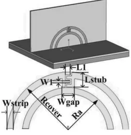
The configuration is shown in Fig. 1, in which the geometrical parameters of the structure are as follows: the outer ring radius of the metamaterial resonator structure Rcover= 10 mm, width of the microstrip Wstrip = 1 mm. In particular, the capacitance impedance
is caused by the magnetic flux generated by the current flow in the digits of the interdigital capacitor. The geometrical parameters of the interdigital capacitor Wgap= 2 mm, W1 = 0.45 mm, Lstub = 2.35 mm,
L1 = 0.8 mm. The out radius of the semi-circular loop antenna Ra = 7.5 mm, width of the microstrips Wstrip= 1 mm. The metamaterial resonator structure and the semi-circular loop antenna are printed on one dielectric substrate, the dielectric substrate is standard Rogers RT5880 with relative permittivity 2.2 and thickness 0.787 mm. The size of the dielectric substrate is 20 mm×20 mm. The two microstrip terminals of the metamaterial resonator structure both connect to the ground. The size of the ground is 20 mm×20 mm. One microstrip terminal of the semi-circular loop antenna connects to the ground, the other connects to the 50 Ohm coaxial cable.
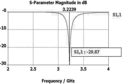
The antenna is simulated using the commercial software Computer Simulation Technology, Microwave Studio (CST MWS), which is based on the finite integration method. The simulation data of the S parameters magnitude in dB is shown in Fig. 2. The resonance frequency is 3.2239 GHz, and impedance bandwidth (S11 < −10) is from 3.19 GHz to 3.26 GHz about 0.07 GHz, the relative bandwidth is about 2.2%. The wave length of the resonance frequencyλis 93.1 mm.
ka= 2πa/λ≈0.6745 <1. The theory limitation of the quality factor
Qchu= 1/(ka) + 1/(ka)3 ≈4.74.
Figure 2. The simulation results of theSparameter magnitude in dB of ESSCLA.
The half-power matched VSWR fractional bandwidth was used to compute the Q value for each system at the resonance frequency ω0:
Chu limit value was obtained using [15]
Qratio(ω0)= 2/ FBWVSWR(ω0)Qchu(ω0)×RE
(5)
where RE mean the radiation efficiency factor. According the simulation data, the FBWVSWR(ω0) ≈ 3.94%, RE = 97.81%, then,
Qratio(ω0)≈10.95.
(a) (b)
Figure 3. The simulation results of matrix coefficients in Z -parameters the ESSCLA. (a) The real part. (b) The imaginary part.
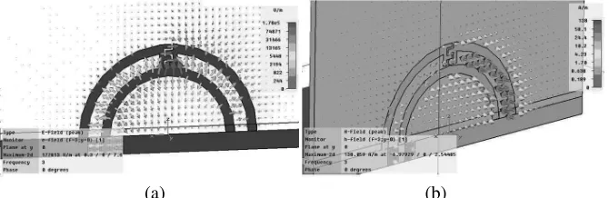
The simulated field distribution of proposed antenna was shown in Fig. 4. The metamaterial resonator structure and the semi-circular loop antenna resonate strongly at the resonance frequency, so that the capacitance impedance caused by the metamaterial resonator structure almost completely counteract the inductive impedance of the semi-circular loop antenna, as shown in Fig. 3. In Fig. 3(a), the real part of the matrix coefficients in Z-parameters is 66.27 Ohm, very close to 50 Ohm, and in Fig. 3(b), the imaginary part of the matrix
(a) (b)
Figure 5. The far-field pattern of the ESSCLA.
Figure 6. The photo of the ESSCLA.
coefficients inZ-parameters is−3.676, very close to 0 at the resonance frequency, so that the ESSCLA can be matched to a 50 Ohm coaxial transmission line source without additional matching network. The far-field radiation pattern is shown in Fig. 5, the peak gain is 4.58 dB, the radiation efficiency is 97.81%, and the overall efficiency is 97.71%. The photo of the ESSCLA is shown in Fig. 6. And the experiments are performed via an HP8720D network analyzer. The experiment data of the S11 are presented in Fig. 7. The measure results accord with the simulation results well.
4. SUMMARY
In this paper, a simple metamaterial resonator structure based electrically small semi-circular loop antenna is simulated and measured. The proposed antenna is miniaturized by using the simple metamaterial resonator structure. The size of proposed antenna is
ka = 0.6745 by Chu limit. The resonance frequency of the proposed antenna is 3.2239 GHz, and impedance bandwidth (S11 < −10) is from 3.19 GHz to 3.26 GHz about 0.07 GHz, the relative bandwidth is about 2.2%. The peak gain is 4.58 dB. The radiation efficiency is 97.81%, the overall efficiency is 97.71%, and Qratio(ω0) ≈ 10.95 at the resonance frequency. The overall structures of ESSCLA can be fabricated on one dielectric substrate, and match conjugate to a 50 Ohm coaxial transmission line source without additional matching network. The proposed antenna has advantages of efficiency, high gain, low cost, small size, and light weight and will be applied to wireless communication systems for required small antennas.
ACKNOWLEDGMENT
This work was supported by the National Nature Science Foundation of China (Grant No. 5063203 and 10474077).
REFERENCES
1. Wheeler, H. A., “Fundamental limitations of small antennas,”IRE
Proc., Vol. 35, 1479–1484, Dec. 1947.
2. Chu, L. J., “Physical limitations in omnidirectional antennas,” J.
Appl. Phys., Vol. 19, 1163–1175, 1948.
3. Thal, H. L., “New radiationQlimits for spherical wire antennas,”
4. Best, S. R., “Low Q electrically small linear and elliptical polarized spherical dipole antennas,” IEEE Trans. Antennas
Propag., Vol. 53, No. 3, March 2005.
5. Foltz, H. D., J. S. McLean, and G. Crook, “Disk-loaded monopoles with parallel strip elements,” IEEE Trans. Antennas Propag., Vol. 46, 1894–1896, 1998.
6. Veselago, V., “The electrodynamics of substances with simultane-ously negative values ofεandμ,”Soviet Physics Uspekhi, Vol. 10, No. 4, 509–514, 1968.
7. Ziolkowski, R. W. and A. Kipple, “Application of double negative metamaterials to increase the power radiated by electrically small antennas,” IEEE Trans. Antennas Propag., Vol. 51, 2626–2640, October 2003.
8. Ziolkowski, R. W. and A. D. Kipple, “Reciprocity between the effects of resonant scattering and enhanced radiated power by electrically emall antennas in the presence of nested metamaterial shells,”Physical Review E, Vol. 72, 036602, September 2005. 9. Ziolkowski, R. W. and A. Erentok, “Metamaterial-based efficient
electrically small antennas,” IEEE Trans. Antennas Propag., Vol. 54, 2113–2130, July 2006.
10. Ziolkowski, R. W. and A. Erentok, “At and beyond the chu limit: Passive and active broad bandwidth metamaterial-based efficient electrically small antennas,” IET Microw., Antennas Propag., Vol. 1, 116–128, February 2007.
11. Kim, H. Y., J. K. Kim, J. H. Kim, Y. J. Kim, and H. M. Lee, “Design of metamaterial structure based electrically small monopole antenna,” 2007 Autumn Microwave & Radio
Wave Conference, Vol. 30, 577–580, September 2007.
12. Ghosh, B., S. Ghosh, and A. B. Kakade, “Investigation of gain enhancement of electrically small antennas using double-negative, single-negative, and double-positive materials,” Physical Review E, Vol. 78, 026611, 2008.
13. Stuart, H. R. and A. Pidwerbetsky, “Electrically small antenna elements using negative permittivity resonators,” IEEE Trans.
Antennas Propag., Vol. 54, 1644–1653, 2006.
14. Stuart, H. R., “The application of negative permittivity materials and metamaterials in electrically small antennas,”IEEE Antennas
and Wireless Propagation Letters, Vol. 6, 460–462, 2007.
15. Erentok, A. and R. W. Ziolkowski, “Metamaterial-inspired efficient electrically small antennas,” IEEE Trans. Antennas
16. Li, L.-W., C.-P. Lim, and M.-S. Leong, “Near fields of electrically small thin square and rectangular loop antennas,” Progress In
Electromagnetics Research, PIER 31, 181–193, 2001.
17. Huang, M. D. and S. Y. Tan, “Efficient electrically small prolate spheroidal antennas coated with a shell of double-negative metamaterials,”Progress In Electromagnetics Research, PIER 82, 241–255, 2008.
18. Balanis, C. A., Antenna Theory, 3rd edition, Wiley, New York, 2005.
19. Ziolkowski, R. W. and E. Heyman, “Wave propagation in media having negative permittivity and permeability,” Physical Review E, Vol. 64, 056625, 2001.
20. Ziolkowski, R. W., “Reply to “Comments on ‘Application of double negative materials to increase the power radiated by electrically small antennas’ ”,” IEEE Transactions on Antennas
and Propagation, Vol. 54, No. 2, February 2006