An Adjustable Speed Control of BLDC Motor
Using Bridgeless Buck–Boost Converter with
Fuzzy Logic Controller
G. Murali Krishna1, D. Divya2
Assistant Professor, Dept. of EEE, VKR&VNB Engineering College, Gudivada, Andhra Pradesh, India1 Assistant Professor, Dept. of EEE, VKR&VNB Engineering College, Gudivada, Andhra Pradesh, India2
ABSTRACT: This paper presents a bridgeless (BL) buck–boost converter-fed brushless direct current (BLDC) motor drive as a cost-effective solution for low-power applications. An approach of speed control of the BLDC motor by controlling the dc link voltage of the voltage source inverter (VSI) is used with a single voltage sensor. This will make the VSI operation at fundamental switching by means of electronic communication of BLCD motor with reduced switching losses. A BL configuration of the buck–boost converter is proposed which offers the elimination of diode bridge rectifier thus reducing the conduction losses those are associated with it. The performance of proposed drive is evaluated over a wide range of speed control and varying supply voltages and MATLAB/Simulink environment is used to simulate the proposed drive.
KEYWORDS: Bridgeless (BL) buck–boost converter, brushless direct current (BLDC) motor, discontinuous inductor current mode (DICM), power factor corrected (PFC), power quality
I.INTRODUCTION
The major constrains in the development of low-power motor drives for household applications such as fans, water pumps, blowers, mixers, etc are EFFICIENCY and COST. The use of the brushless direct current (BLDC) motor in these applications is becoming very common due to wide range of features which includes high efficiency, high flux density per unit volume, low maintenance requirements, and low electromagnetic-interference problems. These BLDC motors are not only limited to household applications, but also suitable for other applications such as medical equipment, HVAC, transportation, motion control, and many industrial tools. In recent years, energy efficiency has become an important aspect of designing any electrical drive system due to the scarcity of the energy resources. The selection of a motor for a particular drive application is the foremost task and it’s depends on variety of parameters such as high efficiency, compact size and good performance over a wide range of speed control.
A BLDC motor contains three phase windings on the stator and permanent magnets on the rotor. The BLDC motor is also known as an electronically commutated motor because an electronic commutation based on rotor position is used rather than a mechanical commutation which has disadvantages like sparking and wear and tear of brushes and commutator assembly.
The prominent feature which makes Brushless DC Motors different from conventional DC motor is the substitution of electrical commutation system with the mechanical self-commutating analogy. To implement the electronic commutation for a three phase BLDC motor, a three-phase full-bridge inverter consisting of six electronic switches is required. At this stage, having an electronic commuted BLDC motor, it becomes easers to take control of the motor characteristics.
conventional brushed DC motors such as higher torque-weight ratio, high dynamic response and better speed vs. torque characteristics.
BLDC motors are nowadays used in every sector of market, especially in the areas of appliances production, aeronautics, medicine, consumer and industrial automations. The BLDC motors are kind of permanent magnet synchronous motors (PMSM), which are driven by commutated direct current (DC) voltage.
Power quality problems have become important issues to be considered due to the recommended limits of harmonics in supply current by various international power quality standards such as the International Electro technical Commission (IEC). A BLDC motor when fed by a diode bridge rectifier (DBR) with a high value of dc link capacitor draws peaky current which can lead to a THD of supply current of the order of 65% and power factor as low as 0.8. Hence, a DBR followed by a power factor corrected (PFC) converter is utilized for improving the power quality at ac mains.
II.LITERATURE SURVEY
Several research papers are proposed and published on BLDC motors some of them are as follows:
A buck–boost converter feeding a BLDC motor based on the concept of constant dc link voltage and PWM-VSI for speed control which has high switching losses is proposed by Singh and Singh.
Gopalarathnam and Toliyat proposed a single-ended primary-inductance converter (SEPIC)-based BLDC motor drive, it is a higher number of current and voltage sensors but it has higher losses in VSI due to PWM switching which restricts its applicability in low-cost application.
Singh and Singh have proposed a Cuk converter-fed BLDC motor drive with the concept of variable dc link voltage which reduces the switching losses in VSI due to the fundamental switching frequency operation for the electronic commutation of the BLDC motor and it also the speed by controlling the voltage at the dc bus of VSI.
A CCM operation of the Cuk converter has been utilized, it requires three sensors but it has low cost and low power rating. For further improvement in efficiency, bridgeless (BL) converters are used which allow the elimination of DBR in the front end. A buck–boost converter configuration is best suited among various BL converter topologies for applications requiring a wide range of dc link voltage control (i.e., bucking and boosting mode). Jang and Jovanovi´c and Huber et al. have presented BL buck and boost converters, respectively.
These can provide the voltage buck or voltage boost which limits the operating range of dc link voltage control. Wei et al. have proposed a BL buck–boost converter which uses three switches which is not a cost-effective solution.
A new family of BL SEPIC and Cuk converters has been reported in the literature but requires a large number of components and has losses associated with it.
This paper presents a BL buck–boost converter-fed BLDC motor drive with variable dc link voltage of VSI for controlling the speed. Here speed is controlled by varying DC link voltage of VSI and by using PI controller it operates in Discontinous inductor current mode to improve powerfactor at ac mains.
III.PROPOSED BRIDGELESS BUCK BOOST CONVERTER FED BLDC MOTOR DRIVE
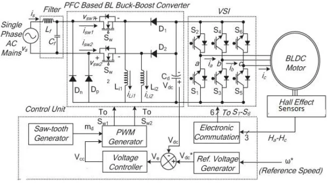
Fig.1 shows the proposed concept of BL buck–boost converter based VSI fed BLDC motor drive. It generally operates in discontinuous inductor current mode(DCIM) for Power factor correction. Speed control is done by using Brushes buck-boost converter. This drive is used for wide ranger of speed control with improved power quality at Ac mains.
OPERATION:
Operating principle of Bridgeless buck–boost converter:
The operation of the PFC BL buck–boost converter is classified into two parts which include the operation during the positive and negative half cycles of supply voltage and during the complete switching cycle.
a) Operation During Positive and Negative Half Cycles of Supply Voltage:
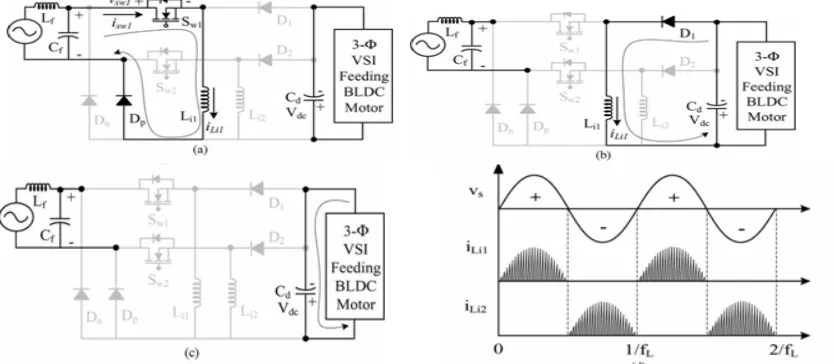
During the positive half cycle of the supply voltage, switch Sw1, inductor Li1, and diodes D1 and Dp are operated to transfer energy to dc link capacitor Cd as shown in Fig. 2(a)–(c). Similarly, for the negative half cycle of the supply voltage, switch Sw2, inductor Li2, and diodes D2and Dnconduct as shown in Fig. 3(a)–(c).In the DICM operation of the BL buck–boost converter, the current in inductor Li becomes discontinuous for a certain duration in a switching period Fig. 2(d) shows the waveforms of different parameters during the positive and negative half cycles of supply voltage.
Fig.2 Operation of the proposed converter in different modes (a)–(c) for a positive half cycle of supply voltage and (d) the associated waveforms. (a) Mode I. (b) Mode II. (c) Mode III. (d) Waveforms for positive and negative half
cycles of supply voltage. b) Operation during Complete Switching Cycle
Three modes of operation during a complete switching cycle are discussed for the positive half cycle of supply voltage as shown hereinafter.
Mode I: In this mode, switch Sw1conducts to charge theinductor Li1; hence, an inductor current iLi1 increases in this
mode as shown in Fig. 2(a). Diode Dp completes the input side circuitry, whereas the dc link capacitor Cd is discharged by the VSI-fed BLDC motor as shown in Fig. 3(d).
Mode II: As shown in Fig. 2(b), in this mode of operation,switch Sw1 is turned off, and the stored energy in inductor
Li1is transferred to dc link capacitor Cduntil the inductor iscompletely discharged. The current in inductor Li1 reduces and reaches zero as shown in Fig. 3(d).
Mode III: In this mode, inductor Li1 enters discontinuousconduction, i.e., no energy is left in the inductor; hence, current iLi1 becomes zero for the rest of the switching period. As shown in Fig. 2(c), none of the switch or diode is
conducting in this mode, and dc link capacitor Cd supplies energy to the load; hence, voltage Vdc across dc link
cycle.Similarly, for the negative half cycle of the supply voltage, switch Sw2, inductor Li2, and diodes Dn and D2 operate
for voltage control and PFC operation.
IV DESIGN F BL BUCK–BOOST CONVERTER:
A PFC BL buck–boost converter is designed to operate in DICM such that the current in inductors Li1 and Li2 becomes discontinuous in a switching period.
Figure.3 Operation of the proposed converter in different modes (a)–(c) for a negative half cycle of supply voltage and (d) the associated waveforms.(a) Mode I. (b) Mode II. (c) Mode III. (d) Waveforms during complete switching cycle.
For a supply voltage of 220V(RMS value),the Dc voltage appears at the input side is nearly 198V
V √ (1)
For a Buck-Boost converter the duty ratio is d= (2)
Generally this converter is designed for DC Voltage limits of 50 volts to 100 volts only with an average value of 100v.so the minimum and maximum values of duty ratio are 0.2016,0.5025 respectively.
A.Design of input inductors(Li1,Li2)
For a BUCK-BOOST converter to operate in critical conduction mode Li1=
( )
(3)
Where R is equivalent total resistence,d is Duty ratio,fs is switching frequency.
The Lic1 is calculated at minimum d value it means for minimum operating voltage of 50v and minimum power of 90w
B. Design of dc link capacitor(cd)
The design of the dc link capacitor is governed by the amount of the second-order harmonic (lowest) current flowing in the capacitor and is derived as follows. =
∆ (7)
Now, the value of the dc link capacitor is calculated for the designed value Vdc des with permitted ripple in the dc link
voltage (ΔVdc) taken as 3% as =
∆ =
/
∆ (8)
C.Design of Input Filter (Lf and Cf ):
A second-order low-pass LC filter is used at the input side to absorb the higher order harmonics such that it is not
reflected in the supply current. The maximum value of filter capacitance is given as =
∅ (9)
Where Ipeak, Vpeak, ωL, represent the peak value of supply current, peak value of supply voltage, line frequency in
radians per second, and displacement angle between the supply voltage and supply current, respectively. Hence, a value
of Cf is taken as 330 nF. Now, the value of inductor Lf is calculated as follows. The value of the filter inductor is
designed by considering the source impedance (Ls) of 4%–5% of the base impedance. Hence, the additional value of
inductance required is given as = + = = + 0.04 (10)
where fc is the cutoff frequency < <
Hence, a value of fc is taken as fsw/10. Finally, a low-pass filter with inductor and capacitor of 1.6 mH and 330 nF is
selected for this particular application.
V. CONTROL OF BL BUCK–BOOST CONVERTER-FED BLDC MOTOR DRIVE
The control of the PFC BL buck–boost converter-fed BLDC motor drive is classified into two parts as follows. a) Control of Front-End PFC Converter:
Voltage Follower Approach:
The control of the front-end PFC converter generates the PWM pulses for the PFC converter switches (Sw1 and Sw2)
for dc link voltage control with PFC operation at ac mains. A single voltage control loop (voltage follower approach) is
utilized for the PFC BL buck–boost converter operating in DICM. A reference dc link voltage (V*dc) is generated as
V*dc = kv w* (11)
Where kv ,w* are the motor’s voltage constant and the reference speed, respectively.
The voltage error signal (Ve) is generated by comparing the reference dc link voltage ( V*dc) with the sensed dc link
voltage (Vdc) as ( ) = ∗( )- ( ) (12)
Where k represents the kth sampling instant. This error voltage signal (Ve) is given to the voltage proportional–
integral (PI) controller to generate a controlled output voltage (Vcc) as
( ) = ( −1) + { ( )− ( −1)} + ( ) (13)
where kp and ki are the proportional and integral gains of the voltage PI control.
Finally, the output of the voltage controller is compared with a high frequency saw tooth signal (md) to generate the
PWM pulses as For vs>0; { if md<vcc then sw1=’ON’ and if md≥ vcc then sw1= ‘OFF’}
For vs<0; { if md<vcc then sw2=’ON ’and if md ≥ vcc then sw2= ‘OFF’}
where Sw1 and Sw2 represent the switching signals to the switches of the converter
b) Control of BLDC Motor: Electronic Commutation:
the BLDC motor. The conduction states of two switches (s1 and s4).A line current iab is drawn from the dc link capacitor whose magnitude depends on the applied dc link voltage.
Table 1: switching states for achieving electronic
commutation of BLDC motor based on hall-effect position signals
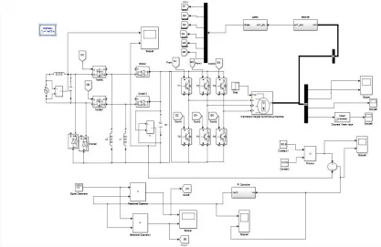
VI. SIMULINK CIRCIUT AND RESULTS
Fig 4: Simulink Circuit of Proposed system
ϴ(0) Hall Signals Switching States
Ha Hb Hc S1 S2 S3 S4 S5 S6
NA 0 0 0 0 0 0 0 0 0
0-60 0 0 1 1 0 0 0 0 1
60-120 0 1 0 0 1 1 0 0 0
120-180 0 1 1 0 0 1 0 0 1
180-240 1 0 0 0 0 0 1 1 0
240-300 1 0 1 1 0 0 1 0 0
300-360 1 1 0 0 1 0 0 1 0
a) SUB CIRCUIT (DECODER):
Fig 5: Simulink circuit of decoder
b. SUB CIRCUIT (GATES):
Fig 6: Simulink circuit of Gates block
RESULTS:
Speed Vs time:
DC link Voltage Vs time:
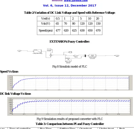
Table 2:Variation of DC Link Voltage and Speed with Reference Voltage:
Vref(v) 0.5 1 2 5 10 20
Vdc(V) 65 70 80 120 120 150
Speed(rpm) 477 620 625 630 650 670
EXTENSION:Fuzzy Controller:
Fig 8 Simulink model of FLC
Speed Vs time:
DC link Voltage Vs time:
Fig 9 Simulation results of proposed converter with FLC
Table 3: Comparison between PI and Fuzzy Controller
s.no Type of controller Rise Time Settling Time Overshoot Under shoot Peak
1 PI 1.45 2.97 134.69 0 115
2 Fuzzy 0.8 1.98 16.16 0 115
VII.CONCLUSION
REFERENCES
[1] C. L. Xia, Permanent Magnet Brushless DC Motor Drives and Controls. Hoboken, NJ, USA: Wiley, 2012.
[2] J. Moreno, M. E. Ortuzar, and J. W. Dixon, “Energy-management system for a hybrid electric vehicle, using ultracapacitors and neural networks,”
IEEE Trans. Ind. Electron., vol. 53, no. 2, pp. 614–623, Apr. 2006.
[3] Y. Chen, C. Chiu, Y. Jhang, Z. Tang, and R. Liang, “A driver for the singlephase brushless dc fan motor with hybrid winding structure,” IEEE
Trans.Ind. Electron., vol. 60, no. 10, pp. 4369–4375, Oct. 2013.
[4] X. Huang, A. Goodman, C. Gerada, Y. Fang, and Q. Lu, “A single sided matrix converter drive for a brushless dc motor in aerospace applications,” IEEE Trans. Ind. Electron., vol. 59, no. 9, pp. 3542–3552, Sep. 2012.
[5] H. A. Toliyat and S. Campbell, DSP-Based Electromechanical Motion Control. Boca Raton, FL, USA: CRC Press, 2004.
[6] P. Pillay and R. Krishnan, “Modeling of permanent magnet motor drives,” IEEE Trans. Ind. Electron., vol. 35, no. 4, pp. 537–541, Nov. 1988.
[7] Limits for Harmonic Current Emissions (Equipment Input Current ≤16 APer Phase), Int. Std. IEC 61000-3-2, 2000.
BIST AND SINGH: ADJUSTABLE-SPEED PFC BRIDGELESS BUCK–BOOST CONVERTER-FED BLDC MOTOR DRIVE 2677
[8] S. Singh and B. Singh, “A voltage-controlled PFC Cuk converter based PMBLDCM drive for air-conditioners,” IEEE Trans. Ind. Appl., vol. 48, no. 2, pp. 832–838, Mar./Apr. 2012.
[9] B. Singh, B. N. Singh, A. Chandra, K. Al-Haddad, A. Pandey, and D. P. Kothari, “A review of single-phase improved power quality acdc converters,” IEEE Trans. Ind. Electron., vol. 50, no. 5, pp. 962–981, Oct. 2003.
[10] B. Singh, S. Singh, A. Chandra, and K. Al-Haddad, “Comprehensive study of single-phase ac-dc power factor corrected converters with high-frequency isolation,” IEEE Trans. Ind. Informat., vol. 7, no. 4, pp. 540–556, Nov. 2011.
[11] S. Singh and B. Singh, “Power quality improved PMBLDCM drive for adjustable speed application with reduced sensor buck-boost PFC converter,” in Proc. 4th ICETET, Nov. 18–20, 2011, pp. 180–184.
[12] T. Gopalarathnam and H. A. Toliyat, “A new topology for unipolar brushless dc motor drive with high power factor,” IEEE Trans. Power
Electron.,vol. 18, no. 6, pp. 1397–1404, Nov. 2003.