Multi-Level Inverter with Reversing Voltage
Topology Using PWM Techniques
T.Sai Sreenivas Prasad1, K. Kiran2, Gowtham Chendra3
M.Tech (PED), Department of EEE, SVPCET, Puttur, Andhra Pradesh, India1
Assistant Professor, Department of EEE, SVPCET, Puttur, Andhra Pradesh, India2
Assistant Professor, Department of EEE, SVPCET, Puttur, Andhra Pradesh, India3
ABSTRACT: This paper proposes single phase and three phase Eleven Level Cascaded H-Bridge Multilevel Inverter and reversing voltage topology by methods based on Sinusoidal PWM control techniques with resistive inductive and induction motor loads. There are 3 types of multilevel inverters named as diode clamped multilevel inverter, flying capacitor multilevel inverter and cascaded multilevel inverter. Compared to diode clamped & flying capacitor type multilevel inverters cascaded H-bridge multilevel inverter has more advantages, but it requires isolated DC sources which is a main drawback of this topology. A new topology with a reversing voltage component requires fewer number of components, switches and carrier signals when compared to other existing topologies. Performance analysis is based on the results of simulation study conducted on the operation of the multilevel inverters using MATLAB/ SIMULINK. The performance parameters chosen the work included fundamental output voltage and total harmonic distortion.
KEYWORDS: Cascaded Multi Level Inverters, Reversing Voltage Topology, Total Harmonic Distortion (THD)
I.INTRODUCTION
Multilevel power conversion technology is a very rapidly growing area of power electronics with good potential for further development and the attractive application of this technology is in the medium-to-high-voltage range, motor drives, power distribution, and power conditioning applications. In recent years, industry demands power in the megawatt level. Controlled ac drives in the megawatt range are usually connected to medium-voltage network. Today, it is hard to connect a single power semiconductor switch directly to medium voltage grids. For these reasons, a new family of multilevel inverters has emerged as the solution for working with higher voltage levels.
In general multilevel inverter can be viewed as voltage synthesizers, in which the high output voltage is synthesized from many discrete smaller voltage levels. The main advantages of this approach are summarized as follows:
They can generate output voltages with extremely low distortion and lower (dv/dt). They draw input current with very low distortion.
They can operate with a lower switching frequency.
Their efficiency is high (>98%) because of the minimum switching frequency. They are suitable for medium to high power applications.
The selection of the best multilevel topology for each application is often not clear and is subject to various engineering tradeoffs. By narrowing this study to the DC/AC multilevel power conversion technologies that do not require power generation.
Multilevel inversion is a power conversion strategy in which the output voltage is obtained in steps thus bringing the output closer to a sine wave and reduces the total harmonic distortion (THD). Various circuit configurations namely diode clamped, flying capacitor and cascaded, etc., have been proposed [5].
II. SYSTEM CONFIGURATION
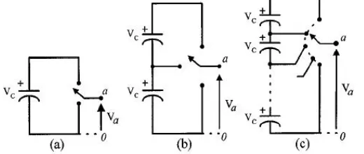
them to reach high voltages with low harmonics without the use of transformers. The general function of the multilevel inverter is to synthesize a desired ac voltage from several levels of dc voltages as shown in Figure 1. The comparison of components required for cascaded and reversing voltage topology per leg is given in the following table-1.
Fig 1. Multilevel Concept for (a) Two Level (b) Three Level and (c) n- Level
Table 1: Component Requirements per Leg of Cascaded Multilevel Inverter and Reversing Voltage Topology Multi level inverter configurations Cascaded inverter
(Per phase) Reversing voltage topology
Main switching Devices 2(m-1) (m+3)
Main diodes 2(m-1) (m+3)
Clamping diodes 0 0
Dc bus capacitors (m-1)/2 (m-1)/2
Balancing Capacitors 0 0
III. CASCADED H-BRIDGE INVERTER
The cascade H-bridge inverter is a cascade of H-bridges, or H-bridges in a series configuration. A single H-bridge inverter and the output Waveform of Eleven-level cascaded Inverter is shown in figure 2. Figure 3 shows the basic power circuit of three phase cascaded H-bridge inverter for Eleven-level inverter respectively. An N level Cascaded H bridge inverter consists of series connected (N-1)/2 number of cells in each phase. Each cell consists of single phase H bridge inverter with separate dc source. There are four active devices in each cell and can produce three levels 0, Vdc/2 and –Vdc/2. To synthesize a multilevel waveform, the ac output of each of the different level H-bridge cells is connected in series and the phase voltage van is the sum of voltages of individual cells, van = v1 + v2 + v3 + ... + vN. For a three phase system, the output of these cascaded inverters can be connected either in star or delta configuration
According to three-phase theory, line voltage can be expressed in term of two phase voltages. For example, the potential between phase A and B is so-called VAB, which can be written as follows:
Vab=Van-Vbn Where
Vab is line voltage
Van is voltage of phase A with respect to point “n” Vbn is voltage of phase B with respect to point “n”
Theoretically, the maximum number of line voltage levels is 2m-1, where m is the number of phase voltage levels. The number of line voltage level depends on the modulation index and the given harmonics to be eliminated. The Eleven-level cascaded inverter, can synthesize up to seventeen-Eleven-level line voltage.
The advantages and disadvantages of cascaded H-bridge inverter is as follows:
Advantages
capacitors.
Switching redundancy for inner voltage levels are possible because the phase voltage output is the sum of each bridges output.
Potential of electric shock is reduced due to the separate DC sources.
Dis-Advantages
Limited to certain applications where separate d.c sources are available.
By increasing the number of levels in cascaded H-Bridge inverter, the components that are required is also increases.
The PWM technique is also become complicated by increasing the number of levels
Reversing Voltage topology is used here to improve the multi-level performance by compensating the disadvantages already mentioned. Especially at higher levels this topology requires less number of components as compared to available inverters.
This topology requires less carrier signals and does not need balancing of the voltages.
A. Single Phase Eleven Level Cascaded H-Bridge Inverter
Fig 2. Configuration of Single-Phase Eleven Level H-Bridge Inverter for RL and Induction Motor Load and Output Wave form
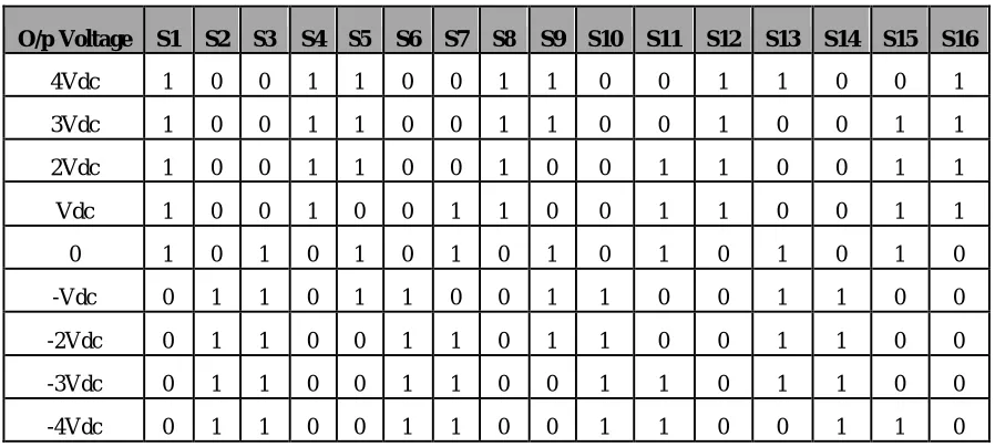
Table 2: Switching States for Eleven Level Cascaded H-Bridge Inverter
O/p Voltage S1 S2 S3 S4 S5 S6 S7 S8 S9 S10 S11 S12 S13 S14 S15 S16
4Vdc 1 0 0 1 1 0 0 1 1 0 0 1 1 0 0 1
3Vdc 1 0 0 1 1 0 0 1 1 0 0 1 0 0 1 1
2Vdc 1 0 0 1 1 0 0 1 0 0 1 1 0 0 1 1
Vdc 1 0 0 1 0 0 1 1 0 0 1 1 0 0 1 1
0 1 0 1 0 1 0 1 0 1 0 1 0 1 0 1 0
-Vdc 0 1 1 0 1 1 0 0 1 1 0 0 1 1 0 0
-2Vdc 0 1 1 0 0 1 1 0 1 1 0 0 1 1 0 0
-3Vdc 0 1 1 0 0 1 1 0 0 1 1 0 1 1 0 0
IV. MULTILEVEL INVERTER USING REVERSING VOLTAGE TOPOLOGY
Fig 3. Block Diagram of Multilevel Inverter Using Reversing Voltage Topology
The Reversing Voltage topology for Eleven level is depicted in figure 5. This topology is a hybrid multilevel topology which separates the output voltage into two parts. One part is named level generation part and is responsible for level generating in positive polarity. This part requires high frequency switches to generate the required levels. The switches in this part should have high-switching-frequency capability. The other part is called polarity generation and is responsible for generating the polarity of the output voltage, which is the low-frequency part operating at line frequency.
Fig 4. Configuration of Single Phase and Three phase Eleven-Level Inverter Using Reversing Voltage Topology
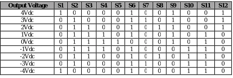
Table 3: Switching States for Eleven Level Inverter Using Reversing Voltage Topology
Output Voltage S1 S2 S3 S4 S5 S6 S7 S8 S9 S10 S11 S12
4Vdc 1 0 0 0 0 1 0 0 1 0 0 1
3Vdc 0 1 0 0 0 1 1 0 1 0 0 1
2Vdc 0 1 1 0 0 1 0 1 1 0 0 1
1Vdc 0 1 1 1 0 1 0 0 1 0 1 0
0Vdc 0 1 1 1 1 0 0 0 1 0 1 0
-1Vdc 0 1 1 1 0 1 0 0 0 1 1 0
-2Vdc 0 1 1 0 0 1 0 1 0 1 1 0
-3Vdc 0 1 0 0 0 1 1 0 0 1 1 0
-4Vdc 1 0 0 0 0 1 0 0 0 1 1 0
V. CARRIER BASED PWM METHODS
The natural sampling techniques for a multilevel inverter are categorized into two and they are:
Single-Carrier SPWM (SCSPWM)
They are
Carrier Disposition PWM Methods
Alternative Phase Opposition Disposition (APOD)
Phase Opposition Disposition (POD) Phase Disposition (PD)
A. Alternate Phase Opposition Disposition(APOD)
The third member of the carriers‟ disposition group is known as Alternative Phase Opposition Disposition (APOD) method. Each carrier of this method is phase shifted by 180 degrees from its adjacent one. It should be noted that POD and APOD methods are exactly the same for a 3-level Inverter.
This method gives almost the same results as the POD method. The major differences are the larger amount of third order harmonics which is not important because of their cancellation in line voltages. Thus, this method results in a better THD for line voltages when comparing to the POD method. The carrier waveforms of this method are illustrated in Figure 5.
Fig 5. APOD Input PWM Phase Opposition Disposition
B. Phase Opposition Disposition (POD)
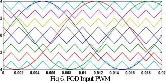
The Phase Opposition Disposition (POD) method, having the carriers above the zero line of reference voltage out of phase with those of below this line by 180 degrees as shown in Figure 6 is one another of the carriers‟ disposition
group. Compared to the PD method, this method has better results from the viewpoint of harmonic performances in lower modulation indices. In POD method, there is no harmonic at the carrier frequency and its multiples and the dispersion of harmonics occurs around them
Fig 6. POD Input PWM
C. Phase Disposition
Fig 7. Phase Disposition Input PWM
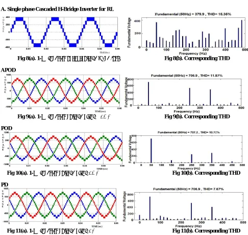
VI. SIMULATION RESULTS A. Single phase Cascaded H-Bridge Inverter for RL
Fig 8(a). 1-Φ inverter outputvoltage wave form Fig 8(b). Corresponding THD APOD
Fig 9(a). 1-Φ inverter voltage using APOD Fig 9(b). Corresponding THD POD
Fig 10(a). 1-Φ inverter voltage using POD Fig 10(b). Corresponding THD PD
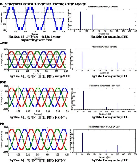
B. Single phase Cascaded H-Bridge with Reversing Voltage Topology
Fig 12(a). 1-Φ Cascaded H-Bridge inverter Fig 12(b). Corresponding THD output voltage wave form
APOD
Fig 13(a). 1-Φ inverter outputvoltage using APOD Fig 13(b). Corresponding THD POD
Fig 14(a). 1-Φ inverter outputvoltage using POD Fig 14(b). Corresponding THD PD
VII. COMPARISON OF RESULTS FOR PROPOSED PWM METHODS Table 4: Results Comparison between Cascaded and Reversing Voltage Topology
PWM Technique Cascaded H-Bridge Inverter (THD%) (RL Load) Reversing Voltage Topology (THD%) (RL Load)
APOD (3-phase) 11.83 7.69
POD (3-phase) 10.52 6.54
PD (3-phase) 7.67 6.54
Single Phase(PD) 15.35 12.64
The experimental verification of this scheme is carried out on R-L load, single-phase and three-phase. Figure 8 to 15 shows the performance of the Eleven-level inverter on R-L load for cascaded and reversing topology. Seven levels are clearly observed in figure 8 and in remaining figures seventeen levels corresponding to line voltages are also clearly observed. For reversing topology POD technique is same as PD because it has only positive carriers i.e., above zero
line. The value of parameters used are R=400 Ω and L=20 mH. If we decrease the L value in the RL load then the THD
also decreases.
VIII. CONCLUSIONS
Here a Reversing Voltage topology is used which has superior characteristics over traditional topologies in terms of required components as switches, voltage balancing, control requirements and reliability. By comparing the results of both topologies, concluded that the harmonic spectrum for reversing voltage topology is good when compared to that of the cascaded H-Bridge inverter with resistive-Inductive and induction motor loads, and also shows better THD for Phase Disposition PWM technique when compared with existing PWM techniques
REFERENCES
1. Hemant Joshi and P. N. Tekwani, IEEE “Multi-level Inverter for Induction Motor Drives: Implementation using Reversing Voltage Topology”,
2010.
2. Ehsan Najafi and Abdul Halim Mohamed Yatim, Senior Member, IEEE Members.“Design and Implementation of a New Multilevel Inverter
Topology”, VOL. 59, NO. 11, NOVEMBER 2012.
3. Mahrous Ahmed, Maha G. Elsheikh, Mahmoud A. Sayed, and Mohamed Orabi, IEEE member “Single-Phase Five-Level Inverter with Less
Number of Power Elements for Grid Connection”, 2012.
4. Xuefeng Hu, Chunying Gong, Xiaolan, Chen xin, Jiayan Zhang,”Analysis of Topology and PWM Strategy for A New Multiple Input and
Multilevel Inverter”2010.
5. Rokan Ali Ahmed, Hew Wooi Ping, S. Mekhilef ,”New multilevel inverter topology with minimum number of switches”2010
6. Gui-Jia Su, ”Multilevel DC Link Inverter”, IAS 2004.
7. Leon M. Tolbert, Thomas G. Habetler, “Novel Multilevel Inverter Carrier-Based PWM Methods”, 1998 IEEE.
8. X.Yun, Y.Zou, X. Liu, and Y. He, “A novel composite cascade multilevel converter,” in Proc. 33rd IEEE IECON, 2007, pp. 1799–1804.
9. S.A. Gonzalez, M. I. Valla, and C. F. Christiansen, “Analysis of a cascade asymmetric topology for multilevel converters,” in Proc. IEEE ISIE,
2007, pp.1027–1032.
10. M. Malinowski, K. Gopal Kumar, J. Rodriguez, and M. A. Pérez, “A survey on cascaded multilevel inverters,”
IEEE Trans. Ind. Electron., vol. 57, no. 7, pp. 2197– 2206, Jul. 2010.
11. M.H. Rashid, „Power Electronics Handbook‟, Elseiver Press, 2003.3. JohnD. Lenk, ‟Simplified Design of Switching Power Supplies‟,
Butterworth-Heinemann,1995.
BIOGRAPHY
K.KIRAN He received his B.Tech (Electrical and Electronics Engineering) degree from JNTU, Hyderabad, at SVPCET, Puttur; M.Tech (EPS) from Jawaharlal Nehru Technological University, Anantapur. He is currently working as Assistant Professor in Electrical and Electronic Engineering, S.V.P.C.E.T, Puttur. His area of interest power systems, operation and control, distribution systems, electrical machines. Power Stability.