227 |
P a g e
SOME STUDIES ON DRILLING BEHAVIOR OF METAL
MATRIX COMPOSITES
Sarbjit Singh
PEC University of Technology, Chandigarh (India)
ABSTRACT
The objective of the present research investigation is to explore the drilling behavior of developed MMCs under the
domain of drilling process parameters; cutting speed, feed and drill geometry. The conventional drilling is used
worldwide for hole making in MMCs. The machine tool parameters (cutting speed and feed) and cutting tool
parameters (tool material, tool hardness, and tool geometry) are some of the important factors which govern the
drilling behavior of MMCs.
Keywords: Drilling, Metal Matrix Composites, Tool Geometry
I INTRODUCTION
Machining is one of the costliest processes in the fabrication of components from MMCs [1]. It is because of the high hardness of the abrasive reinforcement that causes rapid tool wear, increase in cutting forces and deterioration in quality of the machined part especially with conventional HSS tools [2-3]. Therefore for extensive applications of MMCs, the development of cost effective and efficient methods of machining has become the major challenge for the research fraternity.
Drilling of MMCs is the most frequently used technique for hole making which facilitates the assembly or joining of MMCs parts. The objective of the present research investigation is to explore the drilling behavior of developed MMCs under the domain of drilling process parameters; cutting speed, feed and drill geometry. Although other machining process like unconventional machining are used to generate holes in the MMCs but they increases the overall cost of the product and therefore not considered as sustainable solution for cost effective production. The conventional drilling is used worldwide for hole making in MMCs. The machine tool parameters (cutting speed and feed) and cutting tool parameters (tool material, tool hardness, and tool geometry) are some of the important factors which govern the drilling behavior of MMCs.
II EXPERIMENTAL SETUP AND MEASURING INSTRUMENTS
International Journal of Advance Research In Science And Engineering http://www.ijarse.com
IJARSE, Vol. No.2, Issue No.04, April 2013 ISSN-2319-8354(E)
228 |
P a g e
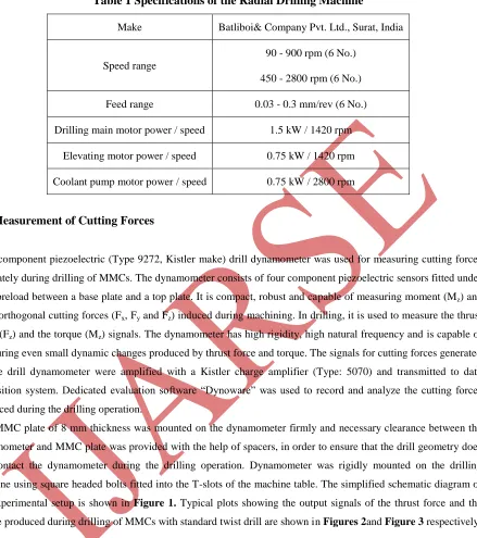
Table 1 Specifications of the Radial Drilling Machine
Make Batliboi& Company Pvt. Ltd., Surat, India
Speed range
90 - 900 rpm (6 No.)
450 - 2800 rpm (6 No.)
Feed range 0.03 - 0.3 mm/rev (6 No.)
Drilling main motor power / speed 1.5 kW / 1420 rpm
Elevating motor power / speed 0.75 kW / 1420 rpm
Coolant pump motor power / speed 0.75 kW / 2800 rpm
2.1 Measurement of Cutting Forces
Four-component piezoelectric (Type 9272, Kistler make) drill dynamometer was used for measuring cutting forces accurately during drilling of MMCs. The dynamometer consists of four component piezoelectric sensors fitted under high preload between a base plate and a top plate. It is compact, robust and capable of measuring moment (Mz) and
three orthogonal cutting forces (Fx, Fy and Fz) induced during machining. In drilling, it is used to measure the thrust
force (Fz) and the torque (Mz) signals. The dynamometer has high rigidity, high natural frequency and is capable of
measuring even small dynamic changes produced by thrust force and torque. The signals for cutting forces generated by the drill dynamometer were amplified with a Kistler charge amplifier (Type: 5070) and transmitted to data acquisition system. Dedicated evaluation software “Dynoware” was used to record and analyze the cutting forces produced during the drilling operation.
229 |
P a g e
Figure 1 Schematic Diagram of the Experimental Setup
Figure 2 Thrust Force Signal Produced by Twist Drill at Feed of 0.12 mm/rev, Cutting Speed of 450
rpm
International Journal of Advance Research In Science And Engineering http://www.ijarse.com
IJARSE, Vol. No.2, Issue No.04, April 2013 ISSN-2319-8354(E)
230 |
P a g e
2.2 Measurement of Surface Roughness
The surface roughness of the drilled hole wall is very important quality characteristic under consideration during drilling behavior of MMCs. The surface roughness of the drilled hole wall is dependent upon tool material, workpiece material, tool geometry, cutting conditions and rigidity of the machine tool used [2, 7]. Both contact and non-contact methods are used to measure the surface roughness of the drilled hole wall. In contact type, Mitutoyo SJ- 400 surface roughness tester as shown in Figure 4 was used to measure surface roughness (Ra) at four positions
of drilled hole wall spaced at 90° interval. Average of four surface roughness values along circumference of drilled hole was taken as surface roughness of the drilled hole wall. The specifications of the Mitutoyo SJ-400 used in the present study are given in Table 2.The photograph of the drilled specimen along with surface roughness tester is shown in Figure 4.
Figure 4 Mitutoyo SJ-400 Surface Roughness Tester
Table 2 Specifications of the Mitutoyo SJ-400
1 Detection method Differential inductance method
2 Roughness standards JIS (JIS B0601-1994-1982), DIN, ISO, ANSI 3 Stylus tip geometry Corn 90°, Radius 5μm, Diamond
4 Measuring range 800μm
231 |
P a g e
.
Figure 5Wyko NT 1100 Surface Roughness Tester
In non-contact type of surface roughness measurement, Wyko NT 1100 profiler based on white light interferometry was used. The integrated optics assembly (IOA) is the core of Wyko NT 1100. The IOA contains a CCD camera, a field-of-view lens, a filter assembly, and an illumination source. Objectives are attached to the bottom of the IOA. Light from the illuminator travels through the IOA and is reflected down to the objective by a beam splitter. Once the light reaches the objective, another beam splitter separates the light into two beams. One beam, the reference beam, reflects from a super smooth reference mirror in the objective, while the other (the test beam) reflects from the surface of the sample and back to the objective. If the surface of the sample is in focus, the two light beams recombine and form interference pattern of light and dark bands called fringes. The interference pattern is received by the CCD camera and the signal is transferred to the computer, where it is processed by Wyco Vision 32 software. Wyco Vision 32 will then produce a graphical output display representing a contour map of the sample surface. The photograph of the Wyko NT 1100 profiler is shown in Figure 5.
2.3 Measurement of Tool Wear
The drill wear measurement is a complex phenomenon as compared to other cutting tools. The tool wear depends upon the tool material, workpiece material, cutting conditions and temperature generated at the tool workpiece interface. The various tool wear mechanism responsible for tool wear are; two body or three body abrasions, adhesion, diffusion and plastic deformation of the cutting edges. Flank wear, crater wear, rupture of cutting edge or groove formation are commonly observed on drill geometry when working with metal matrix composites. The quality characteristics like surface roughness, burr formation and the dimensional accuracy are governed by the tool wear. The abrasion wear of flank face is predominant cause of tool wear in drilling of MMCs [2, 4].
International Journal of Advance Research In Science And Engineering http://www.ijarse.com
IJARSE, Vol. No.2, Issue No.04, April 2013 ISSN-2319-8354(E)
232 |
P a g e
cutting edges at about 1/4th of tool radius from the corner of drill [5]. The average value of wear on two cutting edges was considered as flank wear of the tool geometry.
Figure 7 Toolmakers Microscope
2.5 Burr Formation
Burr is defined as „undesirable projection of material that results from a cutting and shearing operation‟ [6]. The burr
formation causes numerous uninvited features, such as inappropriate contact among current carrying members in electrical components, inappropriate seating of mating surfaces and imprecise assembly of components. The burr formation at the exit side of the drilled hole was analyzed qualitatively in terms of Yes and No. Visual inspection was performed to analyze the burr formation at the exit side of the drilled hole. Figure 7 shows the burr formation on the exit side of drilled hole wall using twist drill point geometry.
Figure 8 Burr Formation at the Exit Side of the Drilled Hole Wall
III CONCLUSION
The present investigation explore the preliminary study on drilling behavior of metal matrix composites in the domain of cutting forces, surface roughness, tool wear and burr formation. The following conclusions can be drawn from the research investigation:
233 |
P a g e
2. The surface roughness of the drilled hole wall surfaces shows the burnishing and honing effect produced by the SiC particles.
3. The predominant wear of cutting tool was observed on flank due to abrasion of SiC particles on the flank Surface.
4. Some burr formation observed on the drilled hole at entrance as well as exit side of the drilled hole.
REFERENCE
1. Tiejun Ma., Hideki Yamaura., Donald A., Koss. Robert C. Voigt., 2003, “Dry sliding wear behavior of cast SiC-reinforced Al-MMCs”, Materials Science and Engineering, Vol. A360, pp.116-125.
2. Monaghan J., and Reilly P.O., 1992, “The drilling of an Al/SiC metal-matrix composite”, Journal of Materials Processing Technology, Vol.33, pp.469-480.
3. Ozben T., Kilickap E., and Orhan C., 2008, “Investigation of mechanical and machinability properties of SiC
particle reinforced Al-MMC”, Journal of Materials Processing Technology, Vol. 198, pp.220-225.
4. Barnes. S., Pashby. I .R., and Hashim A.B., 1999, “Effect of heat treatment on the drilling performance of
Aluminium/SiC MMC”, Applied Composite Materials, Vol. 6, pp.121-138.
5. Davim J. P., and Bapista A.M., 2000, “Relationship between cutting force and PCD cutting tool wear in
machining silicon carbide reinforced aluminium”, Journal of Materials Processing Technology, Vol. 103,
pp.417-423.
6. Ko S. L., and Chang J. E., 2003, “Development of drill geometry for burr minimization in drilling”, CIRP - Manufacturing Technology, Vol. 52, pp.45-48.
7. Sarbjit Singh., Abhishek Singh., InderdeepSingh.,AkshayDvivedi., 2012, “Optimization of the Process Parameters for Drilling of Metal Matrix Composites (MMC) Using Taguchi Analysis”, Advanced Materials