Parametric Study of Skewed Continuous
T-Beam Bridge Super Structure under Seismic
Response
Seethal Joy1, Ananya John2
P.G. Student, Department of Civil Engineering, Indira Gandhi Institute of Engineering and Technology for Women,
Nellikuzhy, Kerala, India1
Associate Professor, Department of Civil Engineering Indira Gandhi Institute of Engineering and Technology for
Women, Nellikuzhy, Kerala, India2
ABSTRACT:Due to space constraints in congested urban areas, newly designed bridges are often skew. However force flow in skew bridges is much more complicated than straight bridges. Generally, structures are subjected to two types of load: static and dynamic. The effect of dynamic load is not considered because the structure is rarely subjected to dynamic loads; more so, its consideration in analysis makes the solution more complicated and time consuming. This feature of neglecting the dynamic forces may sometimes become the cause of disaster, particularly in the case of earthquake. Therefore careful investigation and numerical analysis needs to be performed, in which a skew bridges can be modeled in several ways. In this paper seismic response analysis of four span bridges with skew angles varying from 0° to 60° are developed to investigate the seismic response characteristics of skew T beam bridges. The analytical results have indicated that the skewed bridge responses are quite different from the non-skewed bridge and varying with the skew angles.
KEYWORDS:Skew angle, T-beam Bridge, Response Spectrum Analysis.
I. INTRODUCTION
A bridge is a structure which facilitates passage over an obstacle without closing the way underneath. The required passage may be for railway track, road, pedestrians etc. The obstacle to be crossed may be deep valley with or without of water, road, railway, river etc.
T-beam Bridge is a common choice among the designers for small and medium span bridges. The reinforced cement concrete T-beam bridges consist of concrete slabs supported by a series of longitudinal concrete beams. T-beam bridgeis commonly adopted type bridge for span range 10m to 25m. The structure is so named because the main longitudinal girders are designed as T-beam integral with part of the deck slab, which is cast monolithically with the girders. The number of longitudinal girders depends on the width of the road.Dynamic loads which occur during the operation of the bridge, resulting from forces generated by inertia of deck parts, during the movement of the traffic, wind and earthquake.
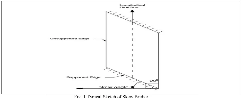
perpendicular or making some angle to crossing. The skew angle can be defined as the angle between the normal to the centreline of the bridge and the centreline of the abutment or pier cap.
Fig. 1 Typical Sketch of Skew Bridge
While performing the seismic risk analysis of a bridge system, it is imperative to identify the seismic vulnerability of bridges associated withvarious states of damage, ranging from loss of serviceability to collapse. Thefailure of the civil infrastructure during seismic events can disrupt human life as well as economy. The seismic vulnerability of bridge structures depends on several aspects of structural form such as whether single or multispan; continuous or internal supports or simply supported; single column or multi column bend; the abutments are straight or skewed. The most vulnerable bridge type in a transportation network is skew bridge. Because of its geometry, the response of the skew bridge during earthquake is more severe than for a straight bridge with identical mass and dimensions. The skew bridges have coupled response in global co-ordinate system and the seismic response increases with the increase in skew angle.
The force flow in skew bridges is much more complex as compared to right-angle bridges. It exhibits a unique seismic response that is triggered by oblique impact.For instance the effects of skew angle on the seismic responses of a bridge to a great extent may be compensated by properly modelling boundary conditions. For the present study a T beam skewed bridge for wide range of skew angles is modelled using CSi Bridge. Modelling, analysis and design of bridge structures have been integrated into CSi Bridge to create the ultimate in computerized engineering tools. The ease with which all of these tasks can be accomplished makes CSi Bridge the most versatile and productive available on the market today. Response Spectrum analysis is carried out and finally the results are compared for various angles of skew angle.
II. RELATED WORK
Deepak C and Sabeena MV[1], The study deals with the finite element modelling of simply supported skew slab with
varying skew angles using ANSYS software. In this paper skew angles varying from 0º to 30º were taken for the study. After the nonlinear finite element analysis of all skew slabs it is revealed that when skew angle increases the uplift at both the acute corners also increases. From the result obtained, they said that, the maximum deflection for skew slabs decreases with the increase in skew angle andthe load carrying capacity increases with increase in skew angle.
history analysis. The analytical results have indicated that the skewed bridge responses are quite different from the non-skewed bridge and varying with the skew angles and also on ground motion characteristics.
ShervinMaleki[3],This paper investigates the validity of seismic design force recommended by AASHTO for single-span bridges. The prescribed force is equal to the products of soil factor, acceleration and tributary weight of the structure. A three dimensional finite element analysis of straight and skewed bridges with skew angles varying from 0 to 60 degrees is used for this study. In the longitudinal direction, the bridges are assumed to be supported either by elastomeric bearings or a pinned support. In the transverse direction, the stiffness of end cross-frames is considered in the analysis. AASHTO’s recommended seismic design force for single-span bridges is compared with the El Centro time history and response spectrum analysis. It is concluded that AASHTO’s recommended design force for single-span straight and skewed bridges could be unsafe in certain cases. An increase in the design force to a level equal to response spectrum value is recommended for such cases.
III. PROBLEM FORMULATION
Bridge Type: Slab on Girder Bridge
Longitudinal Girder Section: 0.3m x 0.3m x 1.9m
Transverse Girder Section: 0.3m x 0.3m x 1.5m
Depth of Deck Slab: 230mm
Wearing Coat Thickness: 75mm
Dimension of Abutment: 1.2m x 12m x 4m
Dimension of Bent Cap: 1.5m x 9.1m x 0.4m
Dimension of Bent: 8.3m x 1.2m x 8m
Grade of Steel: Fe500 and Grade of Concrete: M30
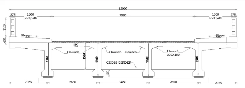
Bearing: Elastomeric Neoprene Bearing. Roller Support at Abutment and Pinned Support at Bent. Cross section and bridge profile are shown in Figure 2 and Figure 3.
Fig. 3 Bridge Profile
IV. MODELLING AND ANALYSIS
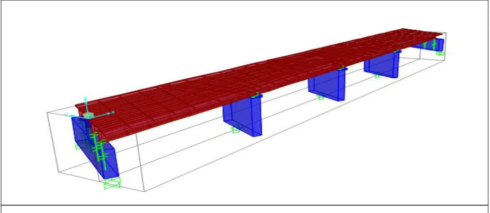
The FEM consists of solving mathematical model which is obtained by idealizing structure as an assembly of various discrete two or three dimensional element which are connected to each other at their nodal points, provided an appropriate number of degrees of freedom is used at each time. The model configuration is varied based on skew angle is changed from 0° to 60°. Continuous four span having length 95.84m bridge is considered for seismic analysis. The load combination considered is 1DL+0.5LL+1EQy at serviceability limit state. Dead Load is self-weight of superstructure and substructure. Live load considered as vehicular load based on IRC 70R loading and earthquake load in transverse direction taken for load combination.The main aim in this study is to observe and conclude bending moment, torsional moment, axial force, transvers displacement and shear force with respect to change in skew angle. The plan layout of the four span continuous skewed T beam bridge is as shown in Figures 4. The cross sectional width of carriageway is kept 12 m for all bridge models.
V. EARTHQUAKE GROUND MOTION
The Response Spectrum analysis of the continuous T Beam Bridge is carried out in CSi Bridge Software. Response spectrum analysis is a statistical type of analysis for the determination of the likely response of a structure to seismic loading. Response spectrum analysis seeks the likely maximum response to these equations rather than the full time history. The earthquake ground acceleration in each direction is given as a digitized response spectrum curves of pseudo spectral acceleration response versus period of the structure. The response spectrum provides a convenient means to summarize the peak response of all possible degree of freedom systems to particular component of ground motion. The ground motion hazard is defined by Response Spectrum, and the standard is selected to be IS 1893 2002. Response Spectrum Function graph automatically created in CSi Bridge software based on input data’s entered in it.
Seismic Zone: III, Seismic Zone Factor:0.16, Soil site is Hard, So Soil Type: I.
An earthquake ground motion record complying with the design acceleration response spectrum obtained from moderate magnitude earthquakes is applied in the transverse direction of the bridge.
VI.RESULT AND DISCUSSION Bending Moment
Fig.5 Bending Moment in whole over the span for different skew angle
This figures show that, the bending moment increases with increases in skew angle.Horizontal Moment of skew bridges are greater than horizontal moment of straight bridge. In these case the exterior girders have more horizontal moment values than interior girders. Hence exterior girders are more susceptible to earthquake forces than interior girders at these skew angles.
0 2000 4000 6000 8000 10000 0 5 .8 5 8 .7 7 5 1 4 .1 5 2 1 6 .6 0 4 2 1 .5 0 8 2 3 .9 6 2 9 .8 1 3 2 .7 3 5 3 8 .1 1 2 4 0 .5 6 4 4 5 .4 6 8 4 7 .9 2 5 3 .7 7 5 6 .6 9 5 6 2 .0 7 2 6 4 .5 2 4 6 9 .4 2 8 7 1 .8 8 7 7 .7 3 8 0 .6 5 5 8 6 .0 3 2 8 8 .4 8 4 9 3 .3 8 8 H o ri z o n ta l M o m en t
Bridge Span Length in m
Stright Bridge 15˚ Skew Bridge 30˚ Skew Bridge
Shear Force
Fig.6 Horizontal Shear Force in whole over the span for different skew angle
This figures show that, shear force increase when skew angle is increases and maximum shear force values observed at two ends of bridges.
Torsional Moment
Fig.7 Torsional Moment in whole over the span for different skew angle
Torsional moment for straight bridge is less than compared with other skew angled bridges. From the above figure, it can say that the torsional moment of 60˚skewangle, posse a wave like pattern.
0 1000 2000 H o ri zo n ta l S h ea r in K N
Bridge Span Length in m
Horizontal Shear V
3in KN
Stright Bridge 15˚ Skew Bridge 30˚ Skew Bridge 45˚ Skew Bridge 60˚ Skew Bridge
0 1000 2000 3000 0 5 .8 5 8 .7 7 5 1 4 .1 5 2 1 6 .6 0 4 2 1 .5 0 8 2 3 .9 6 2 9 .8 1 3 2 .7 3 5 3 8 .1 1 2 4 0 .5 6 4 4 5 .4 6 8 4 7 .9 2 5 3 .7 7 5 6 .6 9 5 6 2 .0 7 2 6 4 .5 2 4 6 9 .4 2 8 7 1 .8 8 7 7 .7 3 8 0 .6 5 5 8 6 .0 3 2 8 8 .4 8 4 9 3 .3 8 8 T o rs io n i n K N m
Bridge Span Length in m
Torsion in KN-m
Stright Bridge 15˚ Skew Bridge 30˚ Skew Bridge
Axial Force
Fig.8 Axial Force in whole over the span for different skew angle
It was found that with an increase in skew angle, axial forces increases. Axial Force value of 15˚ skew bridge have
slight greater value than straight bridge. Axial force of all skew bridges carries a symmetrical pattern whole over the bridge span.
Transverse Displacement
Fig.9Transverse Displacement in whole over the span for different skew angle
Above figures show the change in transverse deflection in entire bridge section increase with increase in skew angle. Maximum displacement occurred at the middle portion of span.
0 500 1000 1500 2000 2500 3000 0 5 .8 5 8 .7 7 5 1 4 .1 5 2 1 6 .6 0 4 2 1 .5 0 8 2 3 .9 6 2 9 .8 1 3 2 .7 3 5 3 8 .1 1 2 4 0 .5 6 4 4 5 .4 6 8 4 7 .9 2 5 3 .7 7 5 6 .6 9 5 6 2 .0 7 2 6 4 .5 2 4 6 9 .4 2 8 7 1 .8 8 7 7 .7 3 8 0 .6 5 5 8 6 .0 3 2 8 8 .4 8 4 9 3 .3 8 8 A xi a l F o rc e, P i n K N
Span Length in m
Axial Force, P in KN
Stright Bridge 15˚ Skew Bridge 30˚ Skew Bridge
45˚ Skew Bridge 60˚ Skew Bridge
0 0.0050.01 0.0150.02 T ra n sv er se D is pl a ce m en t in m
Bridge Span Length in m
Transverse Displacement in m
Stright Bridge 15˚ Skew Bridge 30˚ Skew Bridge
VII. CONCLUSIONS
The behavior of a continuous T beam bridge at seismic force acting on transverse direction of bridge is analyzed and studied for different skewangles. Parameters like Shear force, axial force, bending and torsional moments in entire section of bridge along withdeflections are investigated.
Results show that the maximum value of bending moment in girders increase with increase in skew angle. Shear force of longitudinal girders also increases withincrease in skew angle. Maximum value of torsional moment also increaseswith increase in skew angle.Rate of increase in torsional Momentincreases with increase in skew angle.Transverse displacements for skew bridges also increase with increase in skew angle when it compared with straight bridge. This indicates that the load carrying capacity of skew bridge decrease with increase in skew angle, when transverse seismic force acting on the continuous bridge. Considerable variations are observed in results for skew angles more than 15˚.
REFERENCES
[1] Deepak C and Sabeena M. V, “Effect Of Skew Angle On Uplift And Deflection Of R.C.C. Skew Slab”, International Journal Of Research In Engineering And Technology, vol.4, issue no 5, pp. 105-111,2016
[2] M.N. Haque and M.A.R. Bhuiyan, “Seismic response analysis of simple span concrete deck girder skewed bridge: effect of skew angles”, Journal of Civil Engineering (IEB), 40 (2) 227-237,2012.
[3] ShervinMaleki, “Seismic design force for single-span slab-girder skewed bridges”, Electronic Journal of Structural Engineering, 2001 [4] Ansumankar et.al, “Study on Effect of Skew Angle in Skew Bridges”, International Journal of Engineering Research and Development,
Volume 2, Issue 12, PP. 13-18,2012