PID Based Temperature Controller with High
Accuracy and Faster Control Loop Stability &
Non-Oscillatory Response
Sourav Halder1
Student, Department of Electrical Engineering, SDET-Brainware Group of Institutions, Barasat, West Bengal, India1
ABSTRACT: From the ancient age, humans are trying to control various parameters of various system in this Nature. Now humans have a good control of fire, wind, water (not truly). So there are many intelligent way to control the parameters of a system. The aim of this project is to maintain the temperature constant in a particular area using PID controller. Temperature control has become an important part of any control system operating in a temperature sensitive environment. Whatever the process or the parameters, the principles of control are similar.
KEYWORDS: Proportional, Integral, Derivative, Controller, Temperature.
I. INTRODUCTION
A PID controller is a common method of controlling robots. “PID” is an acronym for Proportional Integral Derivative. As the name suggests, these terms describe three basic mathematical functions applied to the error (error = Set Value Sensor Value, where Set Value is the target value and Sensor Value is the present input value obtained from the sensor) [1].
Main task of the PID controller is to minimize the error of whatever we are controlling. It takes in input, calculates the deviation from the intended behaviour and accordingly adjusts the output so that deviation from the intended behaviour is minimized and greater accuracy can be obtained.
II. PIDCONTROLLER
A. Need for PID Controllers:
a) In Robotics it may be used as a Line follower robot. Line following seems to be accurate when carried out at lower speeds. As we start increasing the speed of the robot, it wobbles a lot and is often found getting off track. Hence some kind of control on the robot is required that would enable us to make it follow the line efficiently at higher speeds. This PID controller helps to overcome this problem. [5]
b) It may be used as a particle swarm optimization approach for optimum design of PID controller in AVR system. This method is proposed to have superior features, including easy implementation, stable convergence characteristics and good computational efficiency. This method was indeed more efficient and robust in improving the step response of an AVR system.[6]
c) It can be used as PID type fuzzy controller and parameters adaptive method. PID type fuzzy controller retains the characteristics similar to the conventional PID controller. [7]
d) A simple event-based PID controller can also be implemented by this controller. It is possible to obtain large reductions in CPU utilization with only minor control performance degradation. [8]
e) It may be used as a PID based temperature controller. [9]
g) This may be also used for A PSO based optimum design of PID controller for a linear brushless DC motor. This method has superior features including easy implementation, stable convergences characteristics and good computational efficiency. The brushless motor is modelled in Simulink and the PSO algorithm is implemented in MATLAB for software implementation. This method is more efficient in improving the step response characteristics such as, reducing the steady state error, rise time, settling time and maximum peak overshoot in speed control of a linear brushless DC motor. [11]
B. Characteristics of P, I, And D controllers:
a) Proportional (P): The proportional term is directly proportional to the error at present. b) Integral (I): The integral term depends on the cumulative error made over a period of time (t). c) Derivative (D): The derivative term depends rate of change of error.
d) Constant (factor): Each term (P, I, D) will need to be tweaked in the code. Hence, they are included in the code by multiplying with respective constants.
i. P Factor (Kp): A constant value used to increase or decrease the impact of Proportional.
ii. I Factor (Ki): A constant value used to increase or decrease the impact of Integral.
iii. D Factor (Kd): A constant value used to increase or decrease the impact of Derivative.
A proportional controller (Kp) will have the effect of reducing the rise time and will reduce, but never eliminate, the
steady-state error.
An integral control (Ki) will have the effect of eliminating the steady-state error, but it may make the transient
response worse.
A derivative control (Kd) will have the effect of increasing the stability of the system, reducing the overshoot, and
improving the transient response. [1]
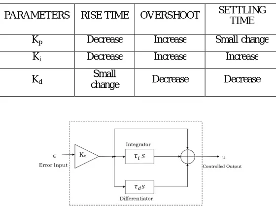
A typical structure of a PID control system is shown in Fig.1. Fig.2 shows a structure of a PID control system. The error signal e(t) is used to generate the proportional, integral, and derivative actions, with the resulting signals weighted and summed to form the control signal u(t) applied to the plant model.
Table 1. A PID controller in a closed-loop system
PARAMETERS RISE TIME OVERSHOOT SETTLING
TIME
Kp Decrease Increase Small change
Ki Decrease Increase Increase
Kd change Small Decrease Decrease
Fig.2 : A structure of a PID control system
where u(t) is the input signal to the multivariable processes, the error signal e(t) shown in equation (1) is defined as:
e(t) =r(t) − y(t) (1)
and r(t) is the reference input signal. [2]
Fig.3: Functional Block Diagram of PID Controller
The functional block diagram of a PID Controller is shown in Fig.3.The PID controller contains three parameters named proportional, integral, and derivative. So this is named after its three correcting terms, whose sum constitutes the manipulated variable (MV) or Control Signal. The proportional, integral, and derivative terms are summed to calculate the total output of the PID controller. And after summing all these terms when we get the manipulated variable, we will input it to the plant. The output of the plant is taken as feedback signal. As we gives a desired input at first, that is why every time this feedback signal compares with that desired set point and maintains the error to minimum and after some iterations it almost reaches that state. Defining u(t) as the controller output, the final form of the PID algorithm is shown in equation (2):
( ) = ( ) = ( ) + ∫ ( ) + ( ) (2)
Where,
Kp: Proportional gain, a tuning parameter
ki: Integral gain, a tuning parameter
kd: Derivative gain, a tuning parameter
e: Error = Set Point – Present Value t: Time or instantaneous time (the present)
III. PROPOSEDTEMPERATURECONTROLLER
A. Problem Statement:
If one needs a smooth change of parameter quickly and without any oscillation then PID (Proportional-Integral-Derivative) controller is a good option. A PID controller can get the desired value of the parameter quickly and can hold the position with great accuracy. In this section, we will briefly discuss about the PID controller. Now, we consider a temperature controller of a heat bath. The main disadvantage of an on-off type controller is the unstable and oscillatory control of the temperature due to the inertia of the heater. Again, if we use a proportional controller, that will lead to a temperature lower than the desired value and will reach to an equilibrium due to the heat loss of the bath. But in this case if there is an accurate calibration, one can get higher accuracy, but the `speed' of system will be slower. Now, if we add a Differential and Integrating circuit with the Proportionalcircuit, the integrator will keep integrating the input until the system reaches to the desired value. And the differential amplifier will add the slopeof the curve to increase the slope and will keep the process fast. [4]
B. Implemented Solution:
For implementing the PID Controller we can use both digital and analog circuits. Digital PID is implemented using integrated circuits while in analog circuit design we can use various circuits using operational amplifiers.
For implement a PID Controller in analog circuit, there are some basic circuits are needed. Like Proportional Controller, Integral Controller (Integrator), Derivative Controller (Differentiator), Adder, Signal Buffer.
Now we prepare the individual circuit and analyse the output:
Purpose of Derivative Controller: The derivative of the process error is calculated by determining the slope of the error over time and multiplying this rate of change by the derivative gain Kd. The derivative term shows the rate of
change of the error over time period t of derivative control (Kd), will have the effect of increasing the stability of the
system, reducing the overshoot, and improving the transient response [1]. The output of derivative term is given in equation (3):
= ( ) (3)
Circuit diagram of ideal differentiator is shown in Fig.4:
Fig.4: Ideal differentiator circuit
So the output will be like as equation (4),
Fig.5: Practical differentiator circuit diagram
Fig.5 shows the practical differentiator circuit. Here the 1K resistance (R1) series with the 10n capacitor (C1) and the 10p capacitor (C2) parallel with the 100M resistance (R2) are used for filtering the output signal. Otherwise we will get a distorted signal output, which will be not our desired.
The input of this circuit is Triangular Wave, Amplitude: 5V, Frequency: 50Hz and the output of this circuit is Square Wave, Amplitude: 5V, Frequency: 50Hz
The output of the differentiator is shown in Fig.6:
Fig.6: Output of differentiator
It produces a voltage output which is directly proportional to the input voltage’s rate-of-change with respect to time. In other words the faster or larger the change to the input voltage signal, the greater the input current, the greater will be the output voltage change in response, becoming more of a “spike” in shape. [2]
Purpose of Integral Controller: An Integral controller is proportional to both the magnitude of the error and the duration of the error. The integral in a PID controller is the sum of the instantaneous error over time (t) and gives the accumulated offset that should have been corrected previously. Consequently, an integral control (Ki) will have the effect of eliminating the steady-state error, but it may make the transient response worse [1]. The integral term is given in equation (5):
= ∫ ( ) (5)
Fig.7: Ideal integrator circuit
So the output will be like as equation (6),
=− ∫ + (6)
Fig.8: Practical integrator circuit diagram
Fig.8 shows the practical integrator circuit. Here the 100K resistance (R2) parallel with the 10uF capacitor (C1) is for filtering the output signal. Otherwise we will get a distorted signal output, which will be not our desired.
The input of this circuit is Square Wave, Amplitude: 5V, Frequency: 50Hz and the output of this circuit is Triangular Wave, Amplitude: 5V, Frequency: 50Hz
The output of the integrator is shown in Fig.9:
From the diagram, it can be seen that while the input remains at zero, so does the output. However when a step input voltage is applied to the input, the output rises. When the step input returns to zero, the output remains at the voltage it last attained.[3]
Purpose of the Proportional Controller: The role of a proportional depends on the present error, I on the accumulation of past error and D on prediction of future error. The weighted sum of these three actions is used to adjust Proportional control is a simple and widely used method of control for many kinds of systems. In a proportional controller, steady state error tends to depend inversely upon the proportional gain (if the gain is made larger the error goes down). The proportional response can be adjusted by multiplying the error by a constant Kp, called the proportional gain [1]. The
proportional term is given in equation (7):
= ∗ ( ) (7)
Circuit diagram of ideal proportional controller is shown in Fig.10,
Fig.10: Ideal proportional controller circuit (Inverting mode)
So the output of the proportional controller will be as equation (8),
=− (8)
Fig.11: Practical proportional controller circuit (inverting mode)
Fig.11 shows the practical proportional controller circuit.The input of this circuit is Square Wave, Amplitude: 5V, Frequency: 50Hz and the output of the circuit is also Square Wave, Amplitude: 5V, Frequency: 50Hz
Fig.12: Output of proportional controller
A high proportional gain results in a large change in the output for a given change in the error. If the proportional gain is very high, the system can become unstable. In contrast, a small gain results in a small output response to a large input error. If the proportional gain is very low, the control action may be too small when responding to system disturbances.
Now finally the PID Controller circuit is shown in Fig.13:
Fig.13: Complete circuit diagram of PID Controller.
IV. ANALYSIS
The output that we have got:
Fig.14 Fig.15
Fig.16 Fig.17: Output of the complete PID controller circuit
We can see here the output reaches to the set point, which is our main objective of this experiment. To control any plant using PID Controller. At first we give a set point to the system and start the system. Then it will start with some process value and compare this value with the set point and generate a manipulated variable signal or control signal by using the three basic controllers, i.e.: Proportional Controller, Integral Controller, Derivative Controller. Then this will flow through the plant and will generate an error signal, which will be further feedback to the input side with the comparator. And this process goes on until the output reaches the desired set point.
V. APPLICATION
A high- accuracy temperature control amplifier can be realized with a proportional- integral- Derivative amplifier response. The integrator function drives the steady- state error to zero. An auto zero instrumentation amplifier INA326 achieves very low offset and drift as well as virtually eliminating the loop error due to 1/f noise. R6 is used simply to provide a feedback path during a DC analysis. This circuit requires an overall feedback path (TEC, etc.) to achieve a steady-state operating point. This amplifier allows temperature control loop stability within in a few tens of mili-degrees.
Bypass capacitors are not shown. This circuit can be used with a DRV593 or an OPA569 TEC driver circuit.
Here we just show the PID portion of a PID based Temperature Controller. If we connect the output of this circuit to a TEC driver and provide a feedback path including a thermistor sensor then it will iterates and will act as a perfect PID based Temperature Controller.
Fig.18: Temperature Controller using PID Fig.19: Temperature Controller Output
VI. CONCLUSION
We simulate the whole project in TINA-TI (Version: 9) software. As TINA-TI is a predefined software, so there is no scope for personal customization. We have to work with those pre-defined functions, pre-programmed, pre-defined components. And also the major problem is that TINA-TI does not allow any close loop system. As PID Controller basically is a close loop controller or we can say that it basically works on close-loop, so that is why this is the major problem faced by us. For this reason we provide a fixed setvalue and a fixed process value at starting with the input and the output will come at once, not in iterative way.
REFERENCES
[1] PID Control Theory by Kambiz Arab Tehrani1 and Augustin MpandaUniversity of Nancy, Teaching and Research at the University of Picardie, INSSET,Saint-Quentin, Director of Power Electronic Society IPDRP,
Tshwane University of Technology/FSATIESIEE-AmiensFrance [2] http://www.electronics-tutorials.ws/opamp/opamp_7.html
[3] http://www.radio-electronics.com/info/circuits/opamp-circuits/operational-amplifier-integrator.php [4] http://www.physics.iitm.ac.in/~sercehep2013/Temperature_Controller.p
[6] Gaing, Zwe-Lee. "A particle swarm optimization approach for optimum design of PID controller in AVR system." Energy Conversion, IEEE Transactions on 19.2 (2004): 384-391.
[7] Qiao, Wu Zhi, and Masaharu Mizumoto. "PID type fuzzy controller and parameters adaptive method." Fuzzy sets and systems 78.1 (1996): 23-35.
[8] Årzén, Karl-Erik. "A simple event-based PID controller." Proc. 14th IFAC World Congress. Vol. 18. 1999.
[9] Shu, Huailin, and Youguo Pi. "Decoupled temperature control system based on PID neural network." networks 1 (2005): 8.
[10] Grassi, Elena, et al. "Integrated system identification and PID controller tuning by frequency loop-shaping." Control Systems Technology, IEEE Transactions on 9.2 (2001): 285-294.