Vol. 4, Special Issue 13, December 2015
FPGA Implementation of Low Power and
High SpeedRadix 2
5
FFT Parallel Procssing
Architecture
A.Suresh Kumar
1,S.Govindaraj
2Assistant Professor, Dept. of Electronics and Communication Engineering, Sasurie College of Engineering, Tiruppur,
Tamilnadu, India1&2
ABSTRACT:Discrete Fourier Transform (DFT) is one of the most employed blocks in many communication and signal processing systems. FFT (Fast Fourier Transform) is a highly efficient procedure to reduce computation time and also improves the performance in DFT. The radix 22, radix 23 and radix 24 FFT architectures are not efficient because of its low utilization of components. In Our aim to design a high data throughput and low complexity VLSI structure for 25-Point FFT architecture. The decimation in time equations are reviewed and implemented in FPGA module according to algorithm architecture. Most of previous architectures were designed using the fixed width multipliers, but our proposed architecture uses canonical signed digit (CSD) multiplier circuit which is used to improve performance and also increase the accuracy of the output. In this complete architecture simulated in Xilinx ISE 14.5 system edition software and implemented in Xilinx SPARTAN-6 FPGA kit. To optimize the power, area and speed of the signal process, pipelining and parallel processing techniques have to be used in this proposal.
KEYWORDS:Fast Fourier Transform(FFT), Discrete Fourier Transform (DFT), Canonical signed digit(CSD) Multiplier, Xilinx, Field Programmable Gate Array(FPGA)
I. INTRODUCTION
According to the latest statistical data technology based on hardware and power efficiency for high performance. Application such as digital signal processing, communications etc. are based on digital function which requires complex functionalities. For this fast fourier transform is one of the efficient method to implement discrete fourier transform due to its reduced computations. Our proposed design “RADIX 25’’ will provide high data throughput and
low complexity VLSI structure .Power , area and speed of the signal processing can be optimized using pipelining techniques.
As the usage of communication equipment increases, the demand for high data rate also increases. The increase in data rate causes distortion in the multipath channel. This leads to emerging multicarrier modulation techniques. This technique divides the high stream data into several low stream data to reduce the effects of distortion. But this technique has low bandwidth efficiency and interchannel interference (ISI) due to the interval between the adjacent channels. OFDM uses the concept of orthogonality of subcarriers that provides high bandwidth efficiency and ISI which are the problems of multicarrier modulation technique. So OFDM is the solution for high data rate communication problems. OFDM is an encoding process that codes digital data on multi carrier frequencies. OFDM is used for digital communication whether it is wired or wireless. The application areas include digital television, audio broadcasting, DSL internet access, wireless networks, power line networks, mobile communications, and asymmetric digital subscriber line (ADSL), wireless local area network (WLAN), and multimedia communication services.
Vol. 4, Special Issue 13, December 2015
architecture twiddle factor is calculated at that instance but in our proposed architecture twiddle factor value is already calculated and stored in memory. This twiddle factor value used for the future calculation which leads to improve the speed of the architecture.
Harini Sharma. D and AddankiPurna Ramesh [1] explained that the performance of Floating point multiplier using Canonical Signed Digit. This canonical signed digit multiplication improve the accuracy of the result which also optimize the performance. In this multiplier is very efficient than the fixed width multiplier because it handle the floating point data in efficient manner.Oh. J.Y, cha. J.S, Kim. S.K, and Lim. M.S [5] described that Implementation of orthogonal frequency division Multiplexing using Radix-N Pipeline Fast Fourier Transform architecture which is improve the speed of the FFT by using the pipeline processing technique.Zhong. G [10] described that an Energy-efficient Reconfigurable Angle-Rotator Architecture which explained the design of low power gate level design and reduce the power consumption. To implement this concept to reduce the power consumption fopipeling and parallel processing techinique.Taesangcho&Hanho Lee [7] described that a high speed and low complexity structure for modified radix 25 FFT processor which used to implemented in gigabit WPAN applications. In this structure complexity is reduced by using specific VLSI structure for radix 25 FFT.
.
II. FAST FOURIER TRANSFORM
Fast Fourier Transform (FFT) is one of the most efficient ways to implement Discrete Fourier Transform (DFT) due to its reduced usage of arithmetic units. DFT is one of those primary tools that are used for the frequency analysis of discrete time signals and to represent a discrete time sequence in frequency domain using its spectrum samples. The Fourier Transform decomposes a wave form basically any real world wave form into sinusoids. It is possible to generalize the Fourier transform on discrete structures such as Finite Groups. The Efficient Computation of such structures, by fast Fourier transform, is essential for high speed computing. FFT algorithms are commonly employed to compute DFTs, but there is a clear distinction is that “DFT” refers to a Mathematical transformation, regardless of how it is computed, whereas “FFT” refers to a specific families of a algorithms for computing DFTs.
Fast Fourier Transform (FFT) is developed by Cooley and Tukeyin 1965. FFT is highly efficient procedure for computingthe DFT of a finite series and requires less numberof computations than that of direct evaluation of DFT. Fast Fourier transform (FFT) is based on decomposition and breaking the sequence into smaller sequences and combining them to get total sequence. The FFT time domain decomposition is usually carried out by a bit reversal sorting algorithm .There are various pipeline structures using radix-2, radix-4 and split radix algorithm.
Fast Fourier Transform (FFT) is one of the most efficient ways to implement Discrete Fourier Transform (DFT) due to its reduced usage of arithmetic units. DFT is one of those primary tools that are used for the frequency analysis of discrete time signals and to represent a discrete time sequence in frequency domain using its spectrum samples. The analysis (forward) and synthesis (inverse) equations of an N point FFT are given below.
𝑋 𝐾 = 𝑁−1𝑥 𝑛 𝑊𝑁𝑘𝑛
𝑛=0 --- (1)
Where,
WNkn = e-j2лkn/N (Twiddle Factor)----(2)
As evident from above equations the basis of both synthesis and analysisequations remains same thus increasing the scope of the architecture to both analyse and synthesize. Dueto increased employability of FFT in modern electronic systems, higher radix FFTs such as radix 4, radix– 8, radix – 2k, split radix, etc. are designed for improved timing and reduced hardware. The basicdifference of the mentioned methods lies in the structure of their butterfly units.
III. RADIX 2 ALGORITHM
TheRadixindicates thesizeofFFT decomposition. InthispaperRadixis2whichis single-RadixFFT. For singleRadix FFTs,
Vol. 4, Special Issue 13, December 2015
` Tofindthenumberofbutterfly stagesrequiredto computeNlength,sequencecanbeM=log2N, and N/2
butterflyoperations are computed in each stage.Inthispaperthereare5butterflystagesand
16butterflyoperationsarecomputedtoproduce32 PointFFT [2].
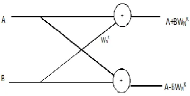
InDIT-FFTthegiven inputsequence isinshuffled orderandtheoutputsequenceisinnaturalorder. Byusing Bit-Reversalinputsequence getsshuffled. TheRadix-2decimation intimeFFTisthebasic formofCooley-Tukeyimplementationalgorithms [1].Radix-2firstcomputes theDFToftheeven indexinputsand theodd indexinputsand then combinesthetworesultstoproduce theentire DFT sequence.ThebasiccomputationblockintheFFT is butterflyinwhichthetwoinputsarecombinedto produce the result.
Figure 1. 2 Point Radix 2 Algorithm
IV. RADIX 2 ALGORITHM
ThispaperProposesandconcentrateon thedesign of32pointFFTanditsperformance
analysis.ByusingVHDLasadesignentity the synthesisandstimulationis doneonXilinxISE
DesignSuite14.5.ADFTDecomposesasequence ofvaluesintocomponents ofdifferentfrequencies. Thisoperation isusefulinmanyfieldsbut computingitdirectlyfromthedefinitionisoften tooslow tobepractical.AnFFTisawayto
computethesameresultmorequickly:Computing aDFTofNpoints, takes O(N2)Arithmetical
operations,whileanFFTcancompute thesame DFT in only O(N log N) operations.FFTs can
decomposedusingDFTsofevenandoddpoints. whichiscalledadecimationin-time(DIT)FFT, or they can decomposed using another approach which iscalledaDecimation-infrequency(DIF) FFT.
Figure 2 represented the block diagram of our proposed architecture. In Which the twiddle factor of various stages are explained in clear manner. Based of the block the sequence of operations are performed in pipelined manner.
V. CANONICAL SIGNED DIGIT MULTIPLIER
In this paper we are using canonic signed digit multiplier instead of fixed width m ultiplier commonly used in various systems. Result of the fixed width multiplier introduce significant error in the output. To reduce the error of the fixed width multiplier a constant bais is added to the retained cell however its products is still large[ 5]. To avoided this CSD multiplier is used in our proposedt architecture.
Vol. 4, Special Issue 13, December 2015
r i=0.1.2…..M-1 takes one of the values 0 &+1 and which the constant values are in the form b0,b1,b2,…bN -1 for each bi for i=0,1,2,…N-1 takes one of the value 0,+1,-1 and where no consecutive bi are nonzero . The CSD multiplier result was obtained addition and shift operation[8].
Figure 2. BLOCK DIGRAM OF 32 POINT RADIX 2 ALGORITHM
The CSD multiplier in normal way the multiplication operation involves two major steps, partial product generation and accumulation. The speed of multiplication can be improved by reducing number of partial product. Number of partial products depends on the number of nonzero digits. Number of nonzero digits is proportional to number of partial products.
The method of CSD is used for multiply the floating point .The representation of floating point contains a sign, mantissa and exponent. The floating point multiplication involves three steps:[8]
1. Multiplication of mantissa part:
In multiplication involves two mantissa part. Mantissa have p-number of bits, the product will be 2p number of bits and finally result will make rounded to p- number of bits. Floating point stores in signed form but multiplier need with unsigned form. So the sign is computed separately by using specific digit.
2. Multiplication of exponent:
The exponent is represented as bias. It differs from various number (i.e) for single the bias is 127 and for double precision the bias is 1023. Based on this bias value this part is multiplied.
3. Computation of sign:
To compute sign bit by using Ex-or operation for 2 sign bits.
Vol. 4, Special Issue 13, December 2015
VI. SIMULATION RESULT AND DISCUSSION
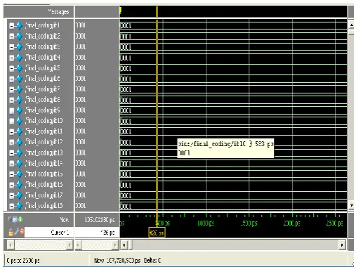
To evaluate performance of the designed architecture the sequence of 32-point input data is giver to the input port of the designed system. The input in form of binary value is given in the MODELSIM by force as the input by selecting the input objects in the design. Figure 3 describes the input sequence of our design.
Figure 3.Input for our proposed system structure
The resultant output of proposed architecture in shown in figure 4. This result produced by this proposed architecture is efficient compared to the previous designed architecture.
The two main significance of the obtained result is,
Delay of this processor is reduced because of using the pipelining architecture.
By using Canonical signed multiplier with common expression sharing technique, to reduce delay Which leads to improve the speed of the process. So, the resultant architecture is very efficient
VII.CONCLUSION
In this paper we have proposed a novel architecture of 32 point FFT design using radix 2 algorithm . It was done using xilinx 14.5 synthesis tool and implemented in spartan 6 FPGA kit. Here CSD multiplier is used to improve the accuracy of the result by handling the floating point value in efficiency manner which leads to improve the performance of radix 25 FFT architecture and also reduces the power consumption up to 33% compared to previous architecture. This concept can be extended to various type of computation extensive applications and might result in area, power consumption and delay reduction.
REFERENCES
1. Harini Sharma, D. andAddankiPurna Ramesh, (2013) “Floating point multiplier using Canonical Signed Digit”, InternationalJournal of Advanced Research in Electronics andCommunication Engineering (IJARECE) Vol. 2, Issue 11.
2. He, S. and Torkelson, (1998) “Designing pipeline FFT processor for OFDM (de)modulation”,proc.IEEE URSI Int. Symp. sig. syst, Electron, PP.257-262.
3. Jung- yeol OH and Myoung-seob LIM, (2005) “New Radix 2 to the 4th power pipeline FFT processor”,IEEETrans,Electron,vol E88-C,No.8. 4. Kim,S.M. Chung, J.G. and Parthi, K.K. (2003) “Low error fixed-width CSD multiplier with efficient sign extension”, IEEE Trans,Circuits
Syst.I,Vol.50,no.12,PP.984-993.
Vol. 4, Special Issue 13, December 2015
6. Parthi, K.K (1999) “VLSI Digital Signal Processing Systems”, John Wiley &sons,USA.
7. Taesangcho&Hanho Lee, (2011) “A High –speed low complexity modified radix 25 FFT processor for gigabit WPAN applications”, IEEE Journal vol.11.
8. Selvakumar, S. Stephy, L. jasmine rani, Vijayalakshmi, G. Vishnudevi, N. and Janakiraman, N. (2014) “Radix 25 FFT architecture implementation in xillinx FPGA” Volume 3, Special Issue 3.
9. Sowjanya, K. LeeleKumari, B. (2013) “Design & Performance Analysis of 32 & 64 point FFT using Radix 2 Algorithm”, AECE-IRAJ international conference.