Methods to Improve the Detection of Failures and
Troubleshooting for Technical Diagnostics in Instrument
Kyaw Zaw Ye, Alexander M. Bain
Department of Computer Science and Software Computer Systems, National Research University of Electronic Technology (MIET), Bld. 5, Pas. 4806, 124498, Zelenograd, Moscow, Russian Federation,
*Corresponding Author:[email protected]
Copyright © 2013 Horizon Research Publishing All rights reserved.
Abstract
This paper focuses on the development of techniques, which is based concept thinning of the flows together with the theory of regression analysis, proposed method of determining the expected number of failures to assess the efficiency of the technical diagnostics in instruments.Keywords
Technical Diagnostics, Failures,Troubleshooting, Identify, Instrument, Reliability
1. Introduction
At the present time, a number of high-tech industries, research and educational processes use many kinds of instrumentations which are greatly improve the efficiency of information processing. Despite the undoubtedly positive effect of the use of instruments, complex ongoing devices, we have to state their lack of effectiveness, due to a number of technical and economic circumstances. In particular, rather acute problem of improving the resiliency and reliability of elements of instrumentations, the life of which often exceeds the standard. In connection with the above, one of the most important requirements for instrument complexes is their high availability and the ability to effectively identify failures[1,2].
Theoretical and practical aspects of technical diagnostics, fault tolerance issues involved in instrument making such famous scientists as P.P Parkhomenko, Caribbean V.V, Sogomonyan E.S, Loaf M.F, A.V Lobanov, Schlichting R. , Rennels D.A, Dolev D. and many others etc.
The analysis showed that the modern industrial technologies used in various fields, require new approaches to ensure their reliability and effective methods of technical diagnostics. In this regard, there is a steady increase in the number of faults and failures, worsening the number of products increase the probability of accidents and crashes. Such a negative situation, which is related to the unreliability of the devices can be neutralized by increased personal skills, able to justify decisions, which is taken in the event of a
negative situation.
2. Methods of Determining the Expected
Number of Failures in the Technical
Diagnostics of Complex
Instrumentation
As noted in the introduction, one of the most important requirements for instrument complexes is their fault tolerance and the ability to effectively identify failures[3]. This paper proposes a mathematical description of the physical model of thinning of the flows in the annex to fault situations, and then the process of technical diagnostics (TD)
can be formalized as follows.
There is an instrumental complex in which the design phase, "laid" fault situations (FS) of the total number of Tfs.
During the TD, they are identified, captured and eliminated. The recovery time during the TD is not taken into account. But TD continues at the end of the process of recovery.
The process of identifying the FS core flow of events - failures. Each detected (shown itself) rejection reduces the intensity of the flow on the value of TFS with probability 1, i.e., feed thins.
To develop a methodology for determining the expected number of failures apply the theory thinning flows, together with the regression analysis [4,5,6] under the following assumptions: the probability of detecting the FS is equal to 1, the probability of making a new FS in the recovery process is equal to 0, a Poisson stream of refusals.
It is known that the thinning flows have functional characteristics which are successfully bind to parameters of statistics TD of devices and equipment of instrumentation.
Among such characteristics are the following:
Mathematical expectation (ME), number of failures will define to (ME):
fs fs
-t p
fs fs
fs
T (p )=n [1-e
]
; (1)(
)
t pfs fs;
fs fs fs fs
t p
=
n t e
−(2) the ME time of total exhaustion failure flow
1
1
1
( )
fs nfs;
fs
P n
t
ϑ
=ϑ
=
∑
(3)As well as the probability of not less than Tfs, but it is
equal to Tfs and nfs exactly failures during number of
p
fsi .They are respectively denoted
D
fs(p )
fs ,D
fs(p )
fs , Last chance essence of the like lihood of complete exhaustion failure flow over time Pfs.In formulas (1) - (3) the following designations: nfs - total
(initial) number of FS, embedded in the devices and equipment of instrumentation; tfs - the instantaneous failure
rate of thinning flow; ϑ - the current variable. Based on the experimental data one can determine the number tfs and nfs
and other characteristics thinning flow are generated by the technical appliance diagnosis unit (apparatus) or the multi-computer system as a whole.
Below is the technique of determining, the expected number of failures on the basis of simple probabilistic methods using empirical data for practical purposes instrumentation. On the observed time interval [0, Pfs ]is Tfs
failures. The expectation value, by definition:
( )
fs(
fs)
M
ξ
∞X dF X
−∞
= ∫
(4)where F - distribution function of the random variable .
1
(
)
,
1
fs fs fs fs t Xfs
e
t p fs fsF X
X
p
e
−
−
−
=
≤
−
(5)The function F(Xfs) takes the value 1 for Хfs=
p
fs, ie All events take place later in point of the time Pfs. We rewrite theintegral (4) with the normalizing
1
1
−
e
−t pfs fs factor thatrightfully regarded as the events that occurred before.
0 1
( ) ( ) (1 ).
1 fs fs fs fs fs p t X
fs fs t p fs
M X dF X X d e
e
ξ ∞ − −
−∞
= ∫ = ∫ −
−
;(6)
Expression
0
(1
)
fs
fs fs
p
t X fs
X d
−
e
−∫
integrate byparts:
0
0
(1
)
0fs fs fs
fs fs fs fs fs fs
p p p
t X t X t X
fs fs fs
X d e
−
−= −
X de
−= −
X e
−+
∫
∫
0
1
fs
fs fs fs fs fs fs
p
t X t X t p
fs fs
fs
e
dX
t e
e
t
− − −
= −
−
∫
1
(
1
t pfs fs(1
))
fs fs fs fs fs
e
t p
t
t
t
−
+
=
−
+
; (7) Then the equation (7) has the form:
(1 )
0
1
1
(1
)
.
1
1
fs fs fs fs
fs
fs fs
fs fs fs fs
t p t p
p
t X fs fs
fs
t p t p
e
t
t
X d
e
e
e
− + − − −−
−
=
∫
−
−
; (8)Rearranging equation (8),
1
(1
)
.
(1
)
fs fs fs fs t p fs fsfs t p
fs
e
t p
m
t
e
− −−
+
=
−
; (9)Transcendental equation, provided that a sufficiently large work tfs pfs can be neglected by (
1
+
t p
fs fs ) in the numerator (9) and the denominator is in the expressionfs fs
t p
e
− . In the case of infinitesimal abovet p
fs fs expressions can be also ignored. Then we have:1
fs fs
m
t
≈
; (10)
The value mfs is biased estimate for the entire set of
events, but in the interval [0,
p
fs], it is not biased and is the sum of Tfs events (failures) at timesp
fs . Theexpected number of failures is defined as follows:
1 1
;
1
.
fs fs T fs fs i fs fs fs T fs ip
m
T
T
t
p
= ==
∑
=
∑
;The expected number of failures is defined as follows. Then:
ξ
=
n
fs
(
)
( )(
)
fs1
t pfs fs Tfs t p n Tfs fs fs fst fs fs
fs
n
P
T
n
e
e
T
(1
fs fs)
fs fs fs fs fs fs fsfs fs
fs t p T
t p T t p n
n T fs
n
e
e
e
T
∞
− −
=
−
∑
=
(1
e
−
t p
fs fs)
T
fse
t p T
fs fs fs=
−
(
1) ... (
1)
fs fs fsfs fs
t p n
fs fs fs fs
n T fs
n
n
n
T
e
T
∞ −
=
−
−
+
∑
To simplify the calculations, we introduce the following notation.
.
fs fs
t p
nw
e
−
=
X
Then,1
! [
Tfs(1
)
Tfs]
fs nw nw
T
×
X
−
X
− −=
1 1
![T
Tfs(1
)
Tfsfs fs nw nw
T
X
−−
X
− −−
2
(T
!)
Tfs(1
)
Tfs]
fsX
nwX
nw − −−
+
−
=
1 2
!{
Tfs(1
)
Tfs[T (1
) (T 1)
]}
fs nw nw fs nw fs nw
T X
−−
X
− −−
X
−
+
X
=
2
1
!
(1
)
(1
)
!
(T
2
)
fs fs
fs fs
T T
fs nw nw
T T
nw fs nw fs fs nw nw
T X
X
X
T X
T X
X
+
+
−
−
−
−
1
2
nw.
fs fs nw
X
T
T X
−
=
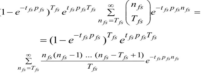
[image:3.595.142.473.79.198.2]−
; (12)Figure 1. The empirical dependence of the failure distribution 1
1
(
(
1)...(
1)
1
!
(1
)
fs
fsС fs
fs fs fs
fs
K
n T
fs fs fs fs nw nw
nw T
n T nw fs
T nw
n n
n
T
X
X
X
X
T
X
∞=
+
−
−
+
=
−
∑
=
=
Figure 1 shows the empirical dependence of the distribution function of the number of failures over time. The value of the failure rate tfs find from equation (10) by defining the value of an empirically constructed by the tabular method of curve and normalized distribution function: a time
p
fs= t1 failures occurred n1 , throughp
fs= t1failures occurred n2, etc.
The results lead to the following conclusions. First, we can estimate the efficiency of TD by analyzing the dependence of
T
(
n
fs) =
f
(
n
fs,
t
fs).
If the time TD ~ t(nfs), the quality (effectiveness)
diagnosis can be regarded as acceptable. If
T n
(
fs
)
>>
fs
p
, on the program of sufficient "hard", the intensity of the flow of failure is low. In this case, you should review and revise the program of the AP. If a large number ofn
fs, it isnecessary to review and revise the production technology products. The function
T n
(
fs
)
=
f n b
(
fs fs
,
)
does not have an unconditional extreme inside the interval of existence. Constrained optimization can be found, if there are known limitations.Second, the model adopted and the results of statistical data processing TD can solve two "side", but is essential to the practice of the problem
3. Methods of Detection of Single
Failures in the Automated System of
Technical Diagnosis
Automation system of technical diagnostics (ASTD) belongs to a class of large technical systems, consisting of a large number of components and elements with a complex structure. Tasks diagnostics (detection and retrieval failures) of such systems is very difficult, so ASTD should be viewed as an object of technological diagnostics (OTD). Then the system can be represented as a set of n of its constituent elements (set), connected by a functional linkages [4].
The probability of working condition of the item is indicated
p
ioti,, and the probability of failureq
ioti, (q
ioti=1-
p
ioti). It is assumed that the failures of the system components mutually independent.Health monitoring systems is the use of special tests, and each of which checks are well-defined to subset of elements. The check is made for the following purposes:
check the system (detecting anyfailureof existing);
refusal to find (search all failed elements).
In the first case, it suffices to apply a test that checks the whole system (the so-called general test). However, sometimes conduct such a test is fundamentally impossible, or inexpedient, since it requires considerable time and (or) it means the advantageous to use an aggregate of a few simple tests.
To the monitor performance and looking for places bounce OTD has a possibility of testing,
h
i
oti
, i = 1, ...,moti , allowing check motiparameters, the nominal value of each of which is provided by a subset of functional elements
Ω
i. The test may consist of supplying the necessary input to measure the response in one or more control points, etc. The results of the application of each test are classified on a "successful" if all the elements of workableΩ
and "not successful" if refused by at least one member ofΩ
i. The application of each test involves some costsc
ioti, which may indicate the time or cost required to verify the parameter value required for this equipment, etc. The set of tests is more convenient to define a matrix,H
oti
=
h
ij
oti
, i = 1, ..., moti, j = 1, ..., noti, lines which swarm match the available tests, and columns - elements of the set. Thus,1,
.
0,
1,..,
, 1...,
i oti
ij oti oti
i
при j
h
при j
i
m
n
∈Ω
=
∈Ω
=
Column vector of coti = {ci oti, ...,
c
m otioti
} determines the cost associated with the use of each test. We assume that for the task of control ASTD existing tests enough , we now define the procedure on the basis of their current classification .
Control processes are classified by a number of attributes: A. In depth, fault localization distinguishes control
processes of the working capacity of the system as a whole and to determine the diagnosis of the state of each element.
B. According to the method of the control procedures can be divided into a sequence and combination. In the first case the choice of the next test is performed with a conventional program which is based on analysis of previous audits. In the second case, the true state of OTI is determined after the application of the entire set of tests.
C. Serial control procedures are usually evaluated in two optimality criteria: minimum average cost of the program and the minimum of the maximum value of this quantity.
D. With an a priori definition of the set of admissible states OTD are usually in to applied two hypotheses : OTD is likely to fail in not more than one member; Various combinations of failed components at the same time.
to identify the state of OTD.
F. From the combination of elements that remain untested after control, distinguishes to control with complete and incomplete coverage of elements of OTD.
G. By the degree of reliability of an inspection - instrumentation distinguish reliable and unreliable control.
H. According to the degree of detail of the information is about the state of OTI, which is received as a result of monitoring distinguish decision-making problem about the true state of OTI in complete and incomplete information [ 2].
We formalize the task to identify the defective item. It is known for a exact failure of a OTD, given a matrix of tests
Hoti and the probability of failure of each element,
q
ioti,i =
1, ..., noti. Need a certain group of selected test sufficient for finding the failed element and define the order of sequential application of a conditional test of this group (program) so that the average value of the total cost of the search procedure to a minimum.
The use of any test
h
ioti can be regarded as a partition of the elements Ω into two subsets: ΩiandΩ
i . At the end of "not successful" failed element is in the subset Ω, at the end of "successful" in a subsetΩ
i.For further localization of failure tests can be used hi∈ Hoti
(here in after referred to as essential), allowing to carry out further divide the subsets Ωi or
Ω
i, containing the failed element. Test hi is essential for a subset Ωi, if:i i i
u
u
Ω
Ω ≠ ∅
Ω Ω ≠ Ω
.The list of essential tests for Ωi, denote Ηi, and if the two tests and hi and hvΩi
Ωi = Ωv
Ωi,, then the list Ηιotileave one, which correspond to lower costs.
List Ηιoti can be a matrix whose columns correspond to
the elements Ωi. Each k-th row of the matrix corresponds to a test of
h
u ik( ),
k = 1, ..., mioti , monitors the health of subsetsΩ
u ik( ) = Ωu
Ωi and at a costZ
u ik( ) = Zu. Subscript without parentheses is used to identify each test in the original matrixΗ oti. Sometimes, for simplicity it will be omitted. Similarly, it can be formed in a matrix of tests that are essential forΩ
i , if further search failed element is carried out in this subset.If OTD is only one possible failure, the sign of the adequacy of the matrix Hoti is containment of any failure for the level of the element which is that all on the columns of the matrix. They must be pair wisely different [6].
4. Conclusion
1. Confirm the reliability of the product individual parameter. Indeed, if the statistics are processed TI single (one) product,
p
fs=
T n
(
fs)
then the flow of failures can assume virtually stationary and therefore,( )
fs fs fs fs
t t ≥T n =
λ
.
2. The plan is reasonably for plan warranty products. Knowing the expected number of fault situation, "embedded" in the product, the number of detected faults, and the probability of failures at certain intervals of time, can determine the amount of the stock of tools and accessories (spare parts), the number and size of repair crews, timelines (stochastic) of their operations, financing activities, etc.
3. The methods of detection of single failures during the technical diagnostics aimed at a variety of tests, sufficient for finding the failed component, and the definition of a conditional order of the consistent application of tests on the criterion of minimizing the average total cost of the search.
REFERENCES
[1] Kyaw Zaw YE, Kukushkin E.S, Lisov O.I. Fault Finding in the multi-computer computer systems based on the "AND-OR" graph / / journal of "The defense complex - the scientific and technical progress of Russia." -M.: Federal State Unitary Enterprise "VIMI," 2012. - № 1. - C.71-75 [2] Kyaw Zaw Ye. Method for determining a single fault with the
technical diagnosis of multiple computer systems / / Scientific and practical journal "Industry aspects of Engineering." - M.: Publishing INGN, 2012. - № 1. - C.18-19.
[3] Kyaw Zaw Ye. Evaluation model of CPU performance of distributed fault-tolerant automation systems / / Modern information technology. International Scientific and Technical Conference: Collected statey., Penza, 2013. - C.124-127.
[4] Kazak D.S. The model for the evaluation of fault tolerance of automated control devices and diagnostics / / Proceedings of the universities. Electronic.-M.: MIET, 2009. - № 1.-C.89-92. [5] Kazak D.S. A mathematical model of CPU performance evaluation of distributed automation systems for process testing / / Scientific and technical journal "Engineering and Technology", Moscow: Publishing House of the "Company Sputnik." - 2008, № 5.-C.37-38.