3312
A NOVEL UNDERWATER IMAGE MOSAICKING USING
IMAGE REGISTRATION BASED ON FLICKER REMOVAL
1,2
ANJIK SUKMAAJI, 1EKO MULYANTO YUNIARNO, 1I KETUT EDDY PURNAMA,
1MOCHAMAD HARIADI
1
Department of Electrical Engineering, Institut Teknologi Sepuluh Nopember, Surabaya, Indonesia 2
Department of Information System, Institut Bisnis dan Informatika Stikom Surabaya, Surabaya, Indonesia
E-mail: 1,[email protected], [email protected], [email protected], [email protected]
ABSTRACT
Video data size could become a problem when it is accessed or stored on mobile devices. Currently, converting video into image mosaicing is the best solution for video data storage on mobile devices. However, underwater video images have more complicated problems. They have common concerns, such as low quality image. The deeper the underwater object is, the more unclear its image become. Although lighting is relatively better in shallow waters, images obtained here often contains flicker, which happens when sunlight is reflected on the water’s surface. Therefore, in the mosaicing process, feature detection must be done first before it is registered. This study attempts to make improvements to underwater image registration process by eliminating flicker so that the feature of the image can be registered. The proposed solution is to use a method to perform flicker detection and removal based on the value (v) in the HSV color model. The method will remove the flicker by automatic selection best value. From the exsperiment result shows 0.65 as the best value (v) for reference flicker. On these values (v), the amount of features that can be detected and registered using SIFT are always higher than using other value (v). Thus, this proposed method can contribute to the image mosaicing registration process
Keywords: Flicker, mosaicking, HSV, sunlight, SIFT
1. INTRODUCTION
The easier and the more effective way to access the internet anywhere and anytime is known as Ubiquitous technology. A device that can be brought anywhere, making it easier for users to access the gadgets and the internet anywhere. Large-scale data management needs to be considered so that it does not burden the gadgets used. Video data is one type of data that has a fairly large size and is becoming concerns to ubiquitous technology. Proper data-processing methods are required so that large-scale video data can be brought using the gadget. One method that can be done is to convert the video into the pictures. Then the images are combined into a single unit that are big enough. The method is called image mosaicking.
Merging multiple images on mosaicking process can be done if the first image features can be matched with the second image features and so on. The diversity of images that will be registered becomes an obstacle. It is almost impossible to design a method that can be applied to all image
registration tasks. The thing that can be done is that each method must consider not only from the type of geometric deformation between images, but also the radiometric deformation and noise, the accuracy of the registration that is done, and the application that is in accordance with the characteristics of the data should be a concern as well.
3313 Flicker is one element that could influence the mosaicking process[2][4][11]. Flicker can be a disturbance in the registration process, so it must be removed before mosaicking is done. Especially underwater image that is very influenced by sunlight. Underwater image containing flicker must be processed first to be eliminated prior to mosaicking. Flicker becomes the focus of the problem of underwater image processing [1..5]. The approach to Eliminate flicker was to use a low pass filter which has good performance in removing flicker on the video image [2]. The previous study [1]. about the new techniques in the flicker removal has not provided significant quality yet. The method if applied, flicker pattern can still be identified. Weakness in the study lies in the reference value of improvements flicker and kernel used.
This study aims to improve the underwater image registration process on underwater mosaicking by improving the image of the registration process. Enhancing the image of registration process is the key to the success of image mosaicking. Image enhancement is done by eliminating the flicker on the basis of the color Value (v) on HSV Color models. This improvement is a development technique for image enhancement carried out previously [1]. The development is done by replacing the kernel 3x3 becomes 9x9. The development of subsequent flicker removal is done by changing the automatic parameter of flicker value from 0.55, 0.6, 0.65, 0.70, 0.75, 0.8, 0.85, 0.9, 0.95 to 1.
2. RELATED WORKS
Results underwater recording process is then performed image processing for a variety of needs. Several studies on image processing in particular the scope of the submarine (underwater) successfully conducted. Underwater image processing for example, Bagheri, Vardy, & Bachmayer succesfully to calculate the amount of benthic[12]. Morino, Fusiello, & Iuretigh, reconstruction of the environment in water[13]. Gracias & Victor determine the trajectory of the camera[14]. Guo, Cheng, & Yin smoothing and estimation of image shift[15]. Image processing techniques mosaicking images are made to objects above the water surface eg for tele-education by Szeliski[16]. Medical applications by Loewke, Camarillo, Jobs, & Salysbury[17]
The study, applying the method Squential Bundle ajustment[18], managed to improve the image before the transformation process in mosaicking. While related to the issue of
underwater noise level and illumination is not homogeneous influencing the mosaicking process can be successfully completed[19].
Iqbal, K., Salam, R.A., Osman, A., and Talib, A.Z., [20] uses Contrast Stretching-based approach to improve the scattering and absorption of underwater color. Contrast Stretching RGB-based algorithm is used to equate the color contrast in the underwater image while HSV-based Contrast Stretching is used to improve the color and illumination of underwater image.
According to Andono, P. N., Purnama, I.K.E. and Hariadi, M. [14], register of underwater image by using scale-invariant feature transform (SIFT) is highly dependent on the image quality. Registration of SIFT Contrast Limited Adaptive Histogram Equalization (CLAHE) approach with Rayleigh distribution in improving the underwater image quality produced 41% of better result than Contrast Stretching.
According to Hitam, M.S., Yussof, W.N.J.H.W., Awaludin, E.A., Bachok, Z., [24], the underwater image enhancement in the last decade has a lot of attention since the visibility level of underwater image is very low. The approach of CLAHE with RGB and HSV color-based in which their results are combined by using Euclidean Norm which effectively increase the visibility of underwater image and result lower value for MSE and higher for PSNR.
.
3. MATERIALS AND METHOD
3.1 Data Acquisition and Location
Data collection image underwater using camera multi view with different height. The image that will be taken to the detection of multi-altitude technique using the camera Panasonic DMC-FT3 models with f/3.3 f-stop, exposure time 1/60 sec, ISO Speed 125, focal length of 5 mm. Data taken at marine karimun Java. Data retrieval results produced in the form of a video with the acquisition duration of 20 minutes. From these data, the analysis is taken 1 minute video and then performed the initial data encoder to process the image with a size of 1280 x 720 with 30fps frame rate, file type conversion result is a windows bitmap (bmp). The entire video data converted to 1800 images.
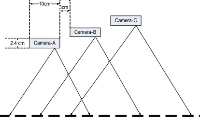
3314 cm with a camera length of 10 cm. Cameras in the paste on the aluminum cross section as shown in figure 2 are equipped with life jackets and the resulting cross-section of PVC pipe camera can float in the water.
Camera-A
Camera-B
Camera-C
2.4 cm 10cm
[image:3.612.93.300.164.287.2]3cm
Figure 1. Multi Altitude Acquisition
With the construction of the design technique, the resulting image has a different point of view and taking image height difference of the fact that the higher order can be used to guide the motion estimation is lower, thus increasing durability and efficiency mosaicing process. Image acquisition process using marker to identification beginning of the underwater images.
3.2 Image Registration based on Flicker Removal
Image registration can be done if both images have been identified the position of each feature[9]. The quality of underwater images that are less obvious or in low qualities, results in problems in the registration process. To be able to process the underwater image as expected, image quality enhancement have to be done. One of methods to improve image quality is by image enhancement[7..9]. Another method to improve image quality, in addition to using image enhancement method, can be done by adjusting the lighting based on underwater image flicker[1]. Underwater image can be determined its flicker pattern by using the formula 1.
∑ ∑ ,
(1) Where
, 1,0, ,,
In another process, image is converted to HSV color model[21..23]. The reason for using HSV color space because HSV color space is a color model that corresponds to the human eye, which has similarities in terms of representing the colors, for example what colors is that color, how bright, or how pure the color is. Flicker in underwater image is a representation of bright illumination pattern that is uneven in an object. The pattern of uneven object lighting can be modeled in advance, then the pattern is used as a reference in the flicker removal at HSV color space, especially the color type V (value). Process to eliminate flicker of color type Value (v) in the HSV color space is done by flattening neighboring flicker using formula 2
.
, ! ! " , " # $ , #
% &
Where
f’(u,v) is the flicker at coordinate (u,v).
w(i,j) is the kernel with the size of 9x9
Underwater Image1
Flicker Map
Value (v) of HSV color
Model
Flicker Removal
Underwater Image2
Flicker Map Value (v) of
HSV color Model
Flicker Removal
[image:3.612.328.514.370.539.2]Reprojection Matching Image Registration
Figure 2. Block diagram of registration process based on flicker removal.
3315 the highest feature number of 10 flicker values that are determined. While on the previous methods [1] a 3x3 kernel is used to eliminate flicker, in this method, 9x9 kernel is used. From the test, 9x9 kernel is the appropriate kernel to support the flicker removal process in this method.
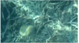
Figure 3. underwaterimage containing flicker
[image:4.612.325.496.90.185.2]Image value (v) in the HSV color space after flicker is eliminated, is converted to RGB color[7][8] and is enhanced using CLAHE method[23..26]. The image that has already been enhanced using CLAHE, then is identified its feature point value. To detect image feature point, SIFT method is used[22][28]. This process is repeated 10 times for each individual image based on the proposed flicker value in this study. The ten times processes are based on the flicker value that are predetermined starting from 0.55, 0.6, 0.65, 0.70, 0.75, 0.8, 0.85, 0.9, 0.95 to 1. Flicker pattern from image figure 3 that using flicker number 0.55, 0.70 and 0.85 show in figure 4,5 and 6.
Figure 4. flicker number 0.55
[image:4.612.117.273.180.266.2]Figure 5. flicker number 0.70
Figure 6. flicker number 0.85
The method is tested on underwater video data that has been converted into underwater image frames[22][23][29]. Image frames that are generated contain a variety of issues, and one of them is the existence of flicker as in Figure 3. Underwater image frames resulted from conversion then are eliminated their flicker using the method with formula 1 as the detection process. For example, when using numbers flicker 12:55, 0.70 and 0.85 is generated patterns flicker as in figure 4, 5 and 6. The pattern is used as a reference to eliminate flicker using formula 2. 12 underwater images are used as a test to determine the development of flicker removal on the proposed method and is expected to further enhance the detection of image feature. The size of the image data in the the experiment is 356 X 640 pixels.
The difference of flicker value parameter between one image with another is very different. With the problem of differences in patterns flicker, the research provides 10 parameters. The system will select one of ten parameters of flicker value. The selection of flicker value is based on detection features that have been compared with the results of the image feature detection with one another. An image that has been done flicker removal by 10 flicker value produces a diverse number of flicker.
(a)
(b)
Figure 7. (a) The underwater image containing flicker. (b) Results flicker removal using the flicker value
[image:4.612.104.269.464.556.2] [image:4.612.356.476.526.698.2]3316 The trial results using image registration flicker value 0.65 as in Figure 10. The image with high luminance in the image can be removed in figure 9a and 9b results on the image. Image containing flicker after flicker removal process using the new method can be seen in Figure 7.
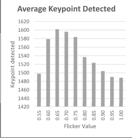
On the average, of 12 image tests using the 10 parameter flicker values, it is resulted in the image feature data that can be detected as in figure 8. The image with a size of 227 840 pixels, the average value of flicker which can be detected as a whole uses 10 flicker removal value is 1540 image feature. The highest value is 1602 and the smallest value is 1489 image feature. The data in Figure 8 show that the base flicker value with the highest number is 0.65, 0.7, and 0.75. Of all the three value bases, the base flicker value of 0.65 has a record with the highest number of detected feature. Thus the registration at the mosaicking process will choose the base value of 0.65 as a reference value of flicker removal. Comparison with the previous method of flicker removal [1], the proposed method can detect 2x more. On the previous method, the average can only detect 883 features, while the proposed method can detect 1540 features.
Figure 8. Average results of image feature detection after flicker removal using a 10 basis flicker value.
Based on the block diagram in Figure 2, flicker removal is done automatically using the flicker value 0.65. After the second image in the correct quality, at registered. For example, in Figure 7, in the image of the second image have been through the process of determining automatically flicker
value is used that is 0.65. 0.65 flicker value determination is done through training in some underwater imagery, and have the highest suitability value. It was shown in the graph drawing 0.65. In the position has detected flicker amount at most.
3.3 Image Mosaicking Based on Flicker Removal
(a)
[image:5.612.313.483.175.361.2](b)
Figure 9. The image that will be registered: (a) The first underwater image, (b) the second underwater image.
Two images in Figure 9 are registered based on homography of image feature point. Based on the homography, the similarity of feature point of Figure 10a and figure 10b. Then, the final stage in image mosaicking is reprojection based on image matching. The result of image reprojection is Figure 11. To test the method, 12 underwater images selected from the underwater video image conversion are used. Flicker removal is done on each image by using the 10 parameter flicker value. The test results in conformance of average feature point with the highest value is 0.65 flicker value. The overall results from testing the method proposed is displayed in Figure 12.
The proposed method is done before the image mosacking, ie at the stage of registration between the two images. Registration is done after flicker eliminated. Flicker removal process is done automatically selects 0:55 flicker value to 1. Each object does not necessarily have to use the flicker value of 0.65, but is selected automatically on most image data. In the data presented, 0.65 is the best value flicker. While the level of compatibility between image keypoint 10a and 10b after flicker removal methods applied are shown in the picture 11. While the results of image mosacking images 9a and 9b shown in Figure 11.
[image:5.612.89.301.395.616.2]3317
[image:6.612.92.295.312.463.2]Figure 10. Conformity of feature point of image 10a and image 10b.
[image:6.612.316.518.405.491.2]Figure 11. The result of Image mosaicking from image 10a and image 10b, based on both homography matrix
Figure 12. Average keypoint match from 12 images that are registered based on 10 flicker values
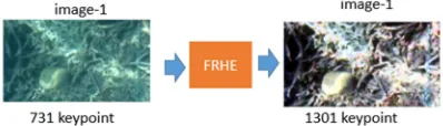
Figure 13 is the result of keypoint detection of an image that successfully repaired using Flicker Removal with Histogram Equition (FRHE). The image of one previously detected keypoint 731, after fixed by FRHE produced in 1301 keypoint detected. as well as to Figure 14, of the 751 into 1508 and the figure 15 of the 751 into 1449 keypoint. In figure 16 is generated matches the image feature of the image 1 and 2. In figure 17 is generated matches the image feature of the image 1 and 3.
Figure 13. Keypoint detection results from FRHE method for image 1
Figure 14. Keypoint detection results from FRHE method for image 2
Figure 15. Keypoint detection results from FRHE method for image 3
Figure 16. The results of the registration image 1 and image 2
Figure 17. The results of the registration image 1 and image 2
4. CONCLUSION
[image:6.612.94.293.645.702.2]3318 provide the right solution for the selection of the flicker value that has the highest effect on the image registration process. The system automatically selects the appropriate flicker point. The number of feature point by eliminating noise in the flicker model will be doubled. This means that the quality of the image by using the proposed method can be increased to 2 times better than the previous image.
From the test results shown in the graph drawing 9 against the graph in Figure 12 shows that the improvement of the quality of the image by the proposed method affect the level of matching feature points. In the graph figure 8, by using a flicker value of 0.65 which is the highest value, testing maching features have proven to 0.65 the highest level according to the 900 match. Development of the proposed method can be used for various applications, especially image quality improvement related to flicker.
REFERENCES
[1] W. N. J. H. W. Yussof, . M. S. Hitam and E. Awalludin, "Performing Contrast Limited Adaptive Histogram Equalization Technique on Combined Color Models for Underwater Image Enhancement," pp. 1-6, 2013.
[2] A. Sukmaaji, E. M. Yuniarno, M. Hariadi and I. K. E. Purnama, "New Approach to Flicker Removal in Underwater Images,"
International Review on Computers and Software (I.RE.CO.S.), 2015.
[3] N. Gracias, S. Negahdaripour, L. Neumann, R. Prados and R. Garcia, "A motion compensated filtering approach to remove sunlight flicker in shallow water images," in OCEANS 2008., 2008.
[4] S. Bazeille, Q. Isabelle and J. Luc , "Color-based underwater object recognition using water light attenuation," Intelligent Service Robotics 5.2 (2012), pp. 109-118, 2012. [5] Y. Swirski, Y. Y. Schechner, B. Herzberg and
S. Negahdaripour, "Underwater Stereo Using Natural Flickering Illumination," in MTS/IEEE OCEANS‘10, Seattle, WA, 2010.
[6] H. Bagheri, A. Vardy and R. Bachmayer, "Strategi for filtering incorect Matches in Seabed Mosaicing," OCEANS, pp. 1-5, 2011. [7] R. C. Gonzalez and . E. Woods, Digital Image
Processing, USA: Prentice Hall, 2008. [8] R. C. Gonzalez, R. E. Woods and L. Steven,
Digital Image Processing Using MATLAB, McGraw Hill, 2010.
[9] J. Guo, S. Cheng and Y. Yin, "Underwater Image Mosaicing Using Maximum Posteriori Image Registration.," in International Symposium, Tokyo, 2000.
[10] N. Gracias and J. Victor, "Underwater
Mosaicing and Trjectory Reconstruction Using Global Alignment," in OCEANS. MTS/IEEE Conference and Exhibition (Vol:4), 2001. [11] H. Bagheri, . A. Vardy and B. R., "Seabed
Image Mosaicing for Benthic Species Counting," in Proceedings of the
Newfoundland Conference on Electrical and Computer Engineering, 2010.
[12] Bagheri, H., Vardy, A., & Bachmayer, R. (2010). Seabed Image Mosaicing for Benthic Species Counting. Newfoundland Conference on electrical and Computer Engineering. [13] Morino, V., Fusiello, & Iuretigh, N. (2000).
3D Mosaicing for Environment
Reconstruction. Pattern Recognation 2000. Proceedings 15th International Conference (volume 3), 358-362.
[14] Gracias, N., & Victor, J. S. (2001). Underwater Mosaicing and Trjectory Reconstruction Using Global Alignment. OCEANS. MTS/IEEE Conference and Exhibition (Volume:4), 4, 2557 - 2563. [15] Guo, J., Cheng, S. W., & Yin, Y. (2000).
Underwater Image Mosaicing Using Maximum Posteriori Image Registration. International Symposium, Tokyo, 393-398. [16] Szeliski, R. (1994). Image mosaicing for
tele-reality applications . Applications of Computer Vision (pp. 44-53). Sarasota, FL: the Second IEEE Workshop.
[17] Loewke, K., Camarillo, D., Jobs, C., & Salysbury, C. (2007). Real-time image mosaicing for medical applications. MEDLINE (pp. 304-9). CA, USA: NCBI. [18] MCLauchlan, P. F., & Jaenicke, A. (2002).
Image Mosaicing using Sequential Bundle Adjustment. Image and Vision Computing, Volume 20, Issues 9–10, , 751–759. [19] Kim, K., Intrator, N., & Nereti, N. (2005).
Image Registration and Mosaicing of Acoustic Camera Image. Radar, Sonar and Navigation, IEEE Proceedings (Volume:152, Issue:4), 263-270.
[20] Iqbal K, Salam RA. Osman A, and Talib AZ, "Underwater Image Enhancement Using an Integrated Colour Model", IAENG
3319 Vol. 34, No. 2, 2007
[21] V. Morino, F. and N. Iuretigh, "3D Mosaicing for Environment Reconstruction," in
Proceedings 15th International Conference (vol. 3), 2000.
[22] A. Sukmaaji, M. Hariadi and I. Purnama, "Keypoint Analysis of Underwater Images with Different Altitude Using SIFT and SURF Descriptor," in SITIA 2013 14th Seminar on Intelegent Technology and Its Application, Surabaya, 2013.
[23] P. N. Andono, E. M. Yuniarno, M. Hariadi and V. Venus, "3D reconstruction of under water coral reef images using low cost multi-view cameras," in Multimedia Computing and Systems (ICMCS), 2012 International Conference on , 2012.
[24] W. N. . J. H. W. Yussof, M. S. Hitam, E. A. Awalludin and Z. Bachok, "Performing Contrast Limited Adaptive Histogram Equalization Technique on Combined Color Models for Underwater Image Enhancement,"
International Journal of Interactive Digital Media, vol. I, pp. 1-6, 2013.
[25] M. Hitam, H. W. Yussof, E. Awalludin and Z. Bachok., "Mixture Contrast Limited Adaptive Histogram Equalization for Underwater Image Enhancement," in Proceeding of The
International Conference on Computer Applications Technology (ICCAT) 1-5, 2013. [26] R. Beohar and P. Sahu, "Performance Analysis
of Underwater Image Enhancement with CLAHE 2D Median Fitering Technique on The Basis of SNR, RMS Error, Mean Brightness," International Journal of Engineering and Innovative Technology (IJEIT), vol. 3, no. 2, pp. 525 -528, 2013. [27] S. Chapra, Applied Numerical Methods with
MATLAB for Engineers and Scientists, 3rd edition, McGraw-Hill, 2012.
[28] N. Shamsuddin, W. Wan Ahmad, B.
Baharudin, M. Mohd Rajuddin and F. Mohd, "Significance Level of Image Enhancement Techniques for Underwater Images," in
International Conference on Computer & Information Science (ICCIS), 2012.