International Journal of Emerging Technology and Advanced Engineering
Website: www.ijetae.com (ISSN 2250-2459,ISO 9001:2008 Certified Journal, Volume 5, Issue 6, June 2015)
418
MIMO Antenna Array Configuration for Minimum Mutual
Coupling
Adham Mohamed Gamal
1, A.M. M. Allam
2 1Teaching Assistant, Faculty of Information Engineering and Technology, German University in Cairo, Cairo, Egypt. 2Professor, Faculty of Information Engineering and Technology, German University in Cairo, Cairo, Egypt.
Abstract- A design of trapezoidal MIMO antenna with a decreased mutual coupling is proposed. The system is designed to operate in the Wi-Fi band (5 GHz) with a bandwidth of 110 MHz. Two different spatial configurations for the same antenna as a basic unit are demonstrated to show the effect of the new configuration. The first configuration has
dimensions of 18.6*64.4*1.554 mm3 while the 2nd
configuration has 33.6*64*1.554 mm3. The 2nd configuration succeeded to decrease the mutual coupling from 6dB to 14dB as a minimum and from 14dB to 27dB as a maximum. There is a perfect match between the measured and the simulated results for the new configuration.
Keywords-- Wi-Fi, MIMO, mutual coupling, DGS. I. INTRODUCTION
Every day, there is a demand for faster bit rate communication techniques. As it’s noticed, starting from 1985, wireless communication systems evolved from 1G to 2G and from 2G to 3G and 4G [1]. All of these systems were invented to cope up with the need of people’s demand. Multiple-input Multiple-output (MIMO) antennas are the solution to the gigabit wireless communication systems [2]. MIMO antennas can increase the capacity of the system by increasing the number of the antennas without any need for an extra frequency spectrum or power [3]. The high potential of MIMO antennas is confirmed by their usage in many different wireless standards such as WLAN [4], WiMax [5], Long Term Evolution (LTE) [6] and Wifi [7].
One main constrain in using MIMO antennas is mutual coupling. One can define mutual coupling as the effect of one of the antennas on the rest of the antennas in the same system. While the antenna is transmitting its power, the other antennas’ receiver is working and will absorb some of this power.
This means that not all the power will be radiated towards the needed receiver. This effect is mutual coupling [8]. Mutual coupling therefore decreases the system’s efficiency and performance in both transmitting and receiving activities.
Many techniques have been studied to prevent mutual coupling between antennas. Parasitic elements [9], DGS designs [10], or electromagnetic gap between the antennas [11] are all examples on these techniques. In this paper, two different configurations for a four antenna MIMO system are proposed to reduce the mutual coupling between the two designs from 6dB to 14dB as a minimum and from 14dB to 27dB as a maximum.
II.ANTENNA DESIGN
The two configurations are implemented on a Rogers RO4350 substrate with a relative permittivity of 3.66, tangential loss of 0.004, and thickness of 1.524, and the two configurations share the same antenna element as a unit cell for the MIMO system. The thickness of copper to make the ground and the antenna is 0.015mm. The antenna
takes the shape of a trapezoidal as demonstrated in Figure
1. All the dimensions of the antenna are listed in Table 1.
For configuration 1, it is made of four symmetrical trapezoidal antennas with a gap of 0.4 mm between each antenna. A gap of 2 mm is left from the four corners. The configuration has total dimensions of 18.6*64.4*1.554
mm3. Each antenna is fed by a 50 Ω matched coaxial cable.
The coaxial cable is positioned to be centered in each antenna with respect to the x-axis and with a separation of
10.2 mm between the feeding point and the base of the
trapezoidal antenna. The 1st configuration is demonstrated
International Journal of Emerging Technology and Advanced Engineering
Website: www.ijetae.com (ISSN 2250-2459,ISO 9001:2008 Certified Journal, Volume 5, Issue 6, June 2015)
419
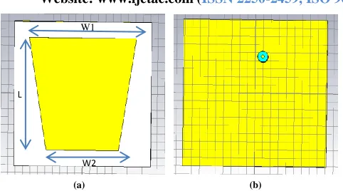
[image:2.612.49.290.126.260.2]
(a) (b)
Figure 1 Antenna element in the proposed structures (a) Front view (b) Back view
Table 1
Dimensions of trapezoidal antenna
L (mm)
W1(mm)
W2(mm)
14.6
14.8
10.2
Figure 2 (a) MIMO configuration 1 (in simulation)
Figure 2 (b) MIMO configuration 1 (after fabrication)
For configuration 2, it is consisted of four antennas. The
1st and the 4th antenna are symmetrical and facing each
other. The 2nd and the 3rd antenna are a 90o rotated version
of the 1st and the 4th antenna. There is a small gap of 0.4 mm is left between the most two far points in each antenna.
This gap is left to make the design as compact as possible and to make sure that the separation between the center of any two antenna to be not more than λ/2 to negate
any grating loops. The design is demonstrated in Figure 3.
All the dimensions regarding the 2nd configuration are
illustrated in Table 2.
Figure 3 (a) MIMO configuration 2 (in simulation)
Figure 3 (b) MIMO configuration 2 (after fabrication)
Table 2
Dimensions of configuration 2
L1(mm)
L2(mm)
W1(mm)
W2(mm)
6
4.6
7.4
7.4
III. RESULTS AND MEASUREMENTS
The 1st configuration is simulated using CST simulation
tool. As it is a symmetric configuration, one can find that antennas, number 1 and number 4, and, number 2 and number 3, will have the exact same s-parameters.
W1
L
W2
L2
L1
W1 W2
1
2
3
4
[image:2.612.323.584.204.343.2] [image:2.612.43.305.320.542.2] [image:2.612.328.581.367.515.2]International Journal of Emerging Technology and Advanced Engineering
Website: www.ijetae.com (ISSN 2250-2459,ISO 9001:2008 Certified Journal, Volume 5, Issue 6, June 2015)
420
Antenna 1 and antenna 2 have a resonance frequency of approximately 5.1 GHz with a bandwidth of 150 MHz. Antenna 3 and antenna 4 have the same response as antenna 2 and antenna 1 simultaneously. This 100 MHz shift in the frequency was from the effect of each antenna
on the resonance frequency of the other. Figure 4 discusses
the simulated and the measured results.
As mentioned before, there is a mutual coupling between the 4 antennas, which allows part of the power to be transferred from any antenna to the rest of the antennas
affecting the total efficiency of the MIMO system. Figure
5 and Figure 6 illustrate the effect of antenna 1 and
antenna 2 simultaneously on the rest of the system
(Measured and Simulated). Table 2 has the value of the 1st
configuration s-parameters at frequency 5 GHz.
Figure 4 Reflection coefficient for antenna 1 and antenna 2 in configuration 1 (Measured and Simulated)
From table 2, one can find that there is a mutual coupling of 6 dB as a min and 13.9 dB as a max.
The 2nd configuration is simulated using CST simulation
tool. It is also a symmetric configuration, so antenna number 1 and 4 share the same s-parameters and antenna number 2 and 3 share the same s-parameters. The four antennas have a resonance frequency of 5 GHz with a
bandwidth of approximately 110 MHz. Figure 7
demonstrates the s-parameters of antenna number 1 and antenna number 2 (Simulated and Measured).
Figure 5 Scattering parameters at 5 GHz frequency of the 1st antenna
in the 1st configuration (Measured and Simulated)
Figure 6 Scattering parameters at 5 GHz frequency of the 2nd antenna
in the 1st configuration (Measured and Simulated)
Table 2
S-parameters of antennas 1 and 2 in configuration 1
S21
-6dB
S12
-6.1dB
S31
-13dB
S32
-9.8dB
S41
-13.9dB
S42
-12.9dB
Figure 8 and Figure 9 illustrate the effect of antenna 1 and antenna 2 simultaneously on the rest of the system
(Simulated and Measured). Table 3 has the value of the 2nd
configuration s-parameters at frequency 5 GHz.
Figure 7 Reflection coefficient for antenna 1 and antenna 2 in configuration 2 (Measured and Simulated)
As noticed from Table 3, the mutual coupling between the 4 antennas has greatly decreased from 6 dB as a minimum to 14.2 dB and from 13.9 dB as a maximum to 26.7 dB.
Figure 8 Scattering parameters at 5 GHz frequency of the 1st antenna
International Journal of Emerging Technology and Advanced Engineering
Website: www.ijetae.com (ISSN 2250-2459,ISO 9001:2008 Certified Journal, Volume 5, Issue 6, June 2015)
421
Figure 9 Scattering parameters at 5 GHz frequency of the 2nd antennain the 2nd configuration (Measured and Simulated)
Table 3
S-parameters of antennas 1 and 2 in configuration 2
S21
-20.4dB
S12
-20.5dB
S31
-26.5dB
S32
-13.9dB
S41
-18dB
S42
-26.7dB
In Figure 10 and Figure 11, the electric field of the 1st antenna in configurations 1 and 2 respectively in demonstrated.
Figure 10 The electric field of the 1st antenna in the 1st configuration
Figure 11 The electric field of the 1st antenna in the 2nd configuration
As one can notice from figure 10 and 11, the effect of antenna number one on the rest of the system has decreased
from the 1st configuration to the 2nd configuration.
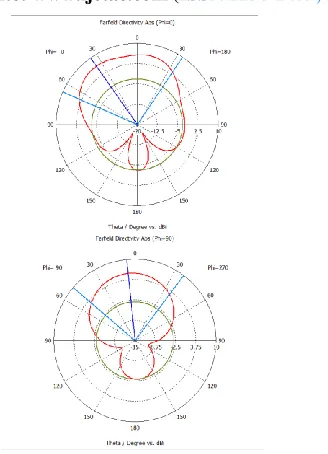
Figure 12 (a, b, c) illustrates the 1st configuration 1st antenna’s far field response in 3D, and polar form.
In the XZ plan, the antenna has a main lobe magnitude
of 5.2 dBi with a direction of 28o. The angular width is
88.7o. In the YZ plan, the antenna has a main lobe
magnitude of 4.08 dBi with a direction of 6o. The angular
width is 109.6o.
Figure 12 (a) Far field response for antenna number 1 in the 1st
configuration in 3D
Figure 12 (b-c) Far field response for antenna number 1 in the 1st configuration in XZ plan and YZ plan respectively
Figure 13 (a, b, c) illustrates the 2nd configuration 1st antenna’s far field response in 3D, and polar form.
In the XZ plan, the antenna has a main lobe magnitude
of 6.38 dBi with a direction of 34o. The angular width is
98.5o. In the YZ plan, the antenna has a main lobe
magnitude of 5.74 dBi with a direction of 6o. The angular
width is 85.8o.
Figure 13 (a) Far field response for antenna number 1 in the 2nd
International Journal of Emerging Technology and Advanced Engineering
Website: www.ijetae.com (ISSN 2250-2459,ISO 9001:2008 Certified Journal, Volume 5, Issue 6, June 2015)
422
Figure 12 (b-c) Far field response for antenna number 1 in the 2ndconfiguration in XZ plan and YZ plan respectively
From figure 11 and figure 12, an enhancement to the radiation efficiency is observed. A slight change in the main lobe magnitude has occurred.
IV. CONCLUSION
Two configurations have been implemented for a four MIMO antenna system to work in the WiFi band. Mutual coupling has been greatly decreased from 6 dB to 14 dB with a difference of 8dB as a minimum and from 14 dB to 27 dB with a difference of 13 dB as a maximum. The far field response of the two systems is approximately the
same in the shape with an enhancement in the 2nd
configuration in the radiation efficiency.
REFERENCES
[1] Amit Kumar, Dr. Yunfei Liu, and Dr. Jyotsna Sengupta, Divya, “Evolution of Mobile Wireless Communication Networks: 1G to 4G”, International Journal of Electronics & Communication Technology, VOL. 1, December 2010.
[2] AROGYASWAMI J. PAULRAJ, DHANANJAY A. GORE, ROHIT U. NABAR, Aswathy K. Sarma, Chinnambeti Raviteja, and HELMUT BÖLCSKEI, “An Overview of MIMO Communications—A Key to Gigabit Wireless”, PROCEEDINGS OF THE IEEE, VOL. 92, February, 2004.
[3] D. Tse and P. Viswanath, Fundamentals of Wireless Communication, Cambridge University Press, New York, 2005. [4] Pawel Kulakowski, and Wieslaw Ludwin, “THE CAPACITY
EVALUATION OF WLAN MIMO SYSTEM WITH MULTI-ELEMENT ANTENNAS AND MAXIMAL RATIO COMBINING”, the 17th Annual IEEE International Symposium on Personal, Indoor and Mobile Radio Communications, 2006. [5] E.T. Tchao, K. Diawuo, W.K. Ofosu ,and E. Affum, “Analysis of
MIMO Systems used in planning a 4G-WiMAX Network in Ghana”, International Journal of Advanced Computer Science and Applications, VOL. 4, 2013.
[6] I.F. Akyildiz, D.M. Gutierrez-Estevez, and E.C. Reyes, “The evolution to 4G cellular systems: LTE-Advanced”, Physical Communication 3, 2010.
[7] Andrea Goldsmith, “Designing Reliable Wi-Fi for HD Delivery throughout the Home”, Quantenna Communications, March, 2009. [8] J. Daniel, “Mutual coupling between antennas for emission or
reception application to passive and active dipole,” IEEE Trans. Antennas Propagat. , VOL. 22, pp. 347-349, March, 1974.
[9] O.F. Ahmed, R.S. Ghoname, and A. A. Zekry “Mutual Coupling Reduction of MIMO Antennas using Parasitic Elements for Wireless Communications”, International Journal of Computer Applications, VOL 62, January, 2013.
[10] Ahmed, M.I. , Sebak, A. , Abdallah, E.A. , and Elhennawy, H., “Mutual coupling reduction using defected ground structure (DGS) for array applications”, Antenna Technology and Applied Electromagnetics (ANTEM), 2012.
[image:5.612.101.265.128.355.2]