Modern Method for Protection of Induction
Motor Using Microcontroller and Wi-Fi
Technology
Harsha Jain, Surbhi Shrivastava
M. Tech* Student, (PEPS), Wainganga College of Engineering, Nagpur, India
Assistant Professor (HOD Electrical), Wainganga College of Engineering, Nagpur, India
ABSTRACT: This project gives a real time implementation of a wireless protection technology of Induction Motor. A low cost and reliable protection scheme has been designed which monitors the parameters of Induction Motor such as voltage, current, temperature, speed of motor and power factor. System measures these parameters by CT, PT, temperature sensor, IR sensor and Zero Crossing Detector and fed to microcontroller Atmega16 which is to be further given to personal computer. For any fault considered in this project the motor is turned off by relay tripping and also a massage is sent on mobile phone of person in charge for protection of motor through Wi-Fi technology. The protection achieved in this project can be faster than classical methods of protection.
KEYWORDS: Microcontroller, Induction Motor, Wi-Fi Introduction
I. INTRODUCTION
The induction motors are the most widely used ac motor due to its low cost, simple and extremely rugged construction, high reliability, high efficiency, reasonably good power factor, low maintenance cost and simple starting arrangement. The mechanical system in industries like paper mill, sugar industry and cement industries are driven by induction motors. Thus the values of current, voltage, temperature of winding and speed of motor becomes very important factor for driving the system. These factors directly affects the performance of motor.
There are various types of faults that are encountered during operation of induction motor. Like electrical faults such as over/under voltage, over load, phase reversing, unbalanced voltage, single phasing and earth fault. The rotor winding failure, stator winding failure and bearing faults are most occurring mechanical faults. The vibration of machine, external moisture, contamination and ambient temperature also affect the induction motor performance. So, in order to improve efficiency of induction motor all these faults has to be taken care of by reliable protection scheme. However, the control of machines is very risky and difficult when machine is on continuous duty. In such cases, wireless control is a considerable solution to eliminate these hazards. Hence, wireless data communication is used in various industries. The wireless monitoring and control scheme proposed in this system ensures the improvement in performance of the motor. The monitoring and controlling operations are done by Wi-Fi technology so as to avoid human hazards.
III. RELATED WORK
Traditionally protection schemes of induction motors suffered from the defect of inflexibility which causes difficulties when dealing with the introduction of special control features which differ from the standard systems, the implementation of unforeseen operational changes after installation of an equipment, the recent trend to depart from standard substation configurations. In such cases relatively high engineering charges and development costs may be incurred. These factors have encouraged the movement towards more flexible approaches; an obvious one is to use programmable sequence controllers. While for many applications it provides economic equipment, for applications above a certain order of complexity the equipment may become bulky with many components.
An alternative approach is the use of microcontrollers systems which offer a number of attractions over other approaches. The approach lends itself to software design and testing aids running either on the microcontroller system itself or on a more powerful large computer. The reliability of such equipment is, of course, of great importance and here again the microprocessor scores well.
Firstly, the principle of the system is such that wide use is made of large-scale integrated circuits which means that the number of components is minimized, resulting in good reliability and small size. Secondly, it is possible to perform a certain amount of self checking in normal operation. The working module mostly consist of analog-to-digital conversion, fault detection, automatic variable time delay achievement, tripping signal generation. The limited dc voltage output of the measuring unit is proportional to the operating current , The voltage is fed to a microcomputer , whose function is to perform the following jobs sequentially through an appropriate programming .
The microcomputer first converts the dc analog input voltage into a digital equivalent in terms of the hexadecimal system. This digital value is tested. If there is a fault, this means that tested value exceeds a stored digital pick-up value, then it will be processed through a software function generator, which consequently determines the action to be performed i.e., relay tripping. The operation time of the relay is determined by a specified time delay subroutine depending upon the value of fault signal. Hence, pulses are generated through an output port of the microcontroller fed to the triggering isolating circuit which triggers the tripping circuit is complete and the fault current will be cleared. If there is no fault, i.e., the digital value of the ADC output is less than the pick-up value, the relay will not operate.
The use of microprocessors in protection relays started a new era in which three main problems are overcome i.e. speed, accuracy and cost, all of which hinder the extensive application of computer relaying devices. With the advent of more and more powerful microprocessors and the development of analytical algorithms, the microprocessor based protective relays may provide considerable correspondences in protection relaying speed, accuracy, reliability, and cost effective schemes to the modern sophisticated power systems.
III. PROPOSED SYSTEM
It is essential that the motor should be monitored continuously so as to improve its performance. The monitoring systems are particularly useful because the systems are able to capture the information from the motor, both real-time and historical over the motor’s life. These real time data is continuously monitored by microcontroller and it is also displayed on Liquid Cr ystal Display i.e., LCD. The protection of induction motor by monitoring and controlling with Wi-Fi technology has proposed in this System. Continuous monitoring of various factors is done by different devices as follows:
Voltage monitoring by potential transformer
Current monitoring by current transformer
Temperature monitoring by LM35
Speed monitoring by IR sensors
The systems also have the ability to keep power factor maintained, which leads to better performance of the motor.
IV. HARDWARE DESCRIPTION
Figure 1. Block Diagram of Proposed System
A. VOLTAGE AND CURRENT MEASUREMENT UNIT
The voltage transformer is used to measure the voltage of the induction motor. The voltage given to the induction motor
is measured using the voltage transformer with the transformation ratio of 230/5V. The current transformer acts like as current sensor as it receives the current signal. The current signal thus received from CT is converted into proportional voltage signal, as microcontroller accepts signals in voltage form only.
B. PIC MICROCONTROLLER
The microcontroller IC which we used is ATMEGA16. It is a 40 pin IC. The Microcontroller receives signal from various monitoring units of the induction motor. protection can be done more effectively and with this microcontroller. Analog inputs are converted into digital signals by ADC within the microcontroller. The data collected from the motor are displayed in Liquid Crystal Display (LCD).
C. LM35 TEMPERATURE SENSOR
The temperature of the motor windings is measured using the LM35 temperature Sensor. The LM35 series are type of precision integrated-circuit temperature sensors. The output of this sensor is linearly proportional the Celsius. For every 10mv, the temperature value will be increase in 1 degree.It can measure the temperature from -55° to +150°C range. The measured temperature from the sensor unit was displayed in LCD and stored in PC through the controller circuit.
D. IR SENSOR
This sensor is used for measurement of speed of motor. It is pair of two LED’s, one which radiates infrared waves and the other one absorbs them. The radiated infrared wave is reflected because of obstacle in its path which is nothing but the white spot set on the cross sectional area of shaft. These reflected waves are absorbed by other LED. The time measured between radiation and absorption generates pulses for microcontroller which are directly proportional to speed of motor.
It senses the zero crossing of voltage and current waves. The difference between the time of zero crossing of two waves gives the phase angle between them and thus the power factor on induction motor.
V. RESULT AND DISCUSSION
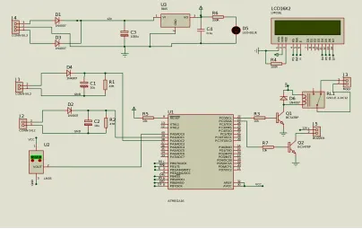
The Fig.2 represents the complete view of the Proteus Software implementation of the induction motor monitoring and control system.
Figure 2. Simulation Representation of Proposed System
The temperature of the motor windings is measured using LM35 temperature sensor. The current and voltage rating of the induction motor, speed of the induction motor are measured using appropriate measuring unit and it can be displayed on LCD display. This paper is based on ongoing project whose testing is yet to be done. Thus actual results have not been presented. The system is expected to monitor the parameters of induction motor and send message on mobile phone when the values of those parameters crosses the limitations prescribed in programming of microcontroller. Hence, preventative action can be taken for protection of motor before actual fault occurs in the system.
VI. CONCLUSION
The induction motors have now become very popular as compared to other motors for many of the industries because its low cost, simple and extremely rugged construction, high reliability, high efficiency, reasonably good power factor, low maintenance cost. Induction motors are used in various industries such as, paper mill, Sugar industry, for driving the mechanical systems. The maintenance of an induction motor is very essential. The monitoring of induction motor through wired communication is not only expensive b u t a l s o t h e data communication may affect due to physical conditions like human hazards. Hence wireless communication becomes a praiseworthy substitute for not only monitoring but also the control of induction motor. It enhances the performance of the motor. The proposed system can measure, monitor and control the most important parameters like voltage, current, temperature, speed and Power factor of the induction motor. These real values are
VCC G N D VCC 12V R S R
W E D4 D5 D6 D7
RS RW E D4 D5 D6 D7 GND GND 1 2 V 12V PB0/T0/XCK 1 PB1/T1 2 PB2/AIN0/INT2 3 PB3/AIN1/OC0 4 PB4/SS 5 PB5/MOSI 6 PB6/MISO 7 PB7/SCK 8 RESET 9 XTAL2 12 XTAL1 13 PD0/RXD 14 PD1/TXD 15 PD2/INT0 16 PD3/INT1 17 PD4/OC1B 18 PD5/OC1A 19 PD6/ICP1 20 PD7/OC2 21 PC0/SCL 22 PC1/SDA 23 PC2/TCK 24 PC3/TMS 25 PC4/TDO 26 PC5/TDI 27 PC6/TOSC1 28 PC7/TOSC2 29 PA7/ADC7 33 PA6/ADC6 34 PA5/ADC5 35 PA4/ADC4 36 PA3/ADC3 37 PA2/ADC2 38 PA1/ADC1 39 PA0/ADC0 40 AREF 32 AVCC 30 U1 ATMEGA16 D 7 1 4 D 6 1 3 D 5 1 2 D 4 1 1 D 3 1 0 D 2 9 D 1 8 D 0 7 E 6 R W 5 R S 4 V S S 1 V D D 2 V E E 3 LCD16X2 LM016L 1 2 J1 CONN-SIL2 1 2 J2 CONN-SIL2 D4 1N4007 D2 1N4007 27.0 3 1 VOUT 2 U2 LM35 VI
1 VO 3
G N D 2 U3 7805 D1 1N4007 D3 1N4007 1 2 3 J4
CONN-SIL3 C31000u
transferred through the Wi-Fi technology to the mobile phone and also to PC. Thus the system facilitates guidance for preventive maintenance and predictive failure analysis.
VII. FUTURE SCOPE
The monitoring and controlling system of the induction motor can be implemented in the industries and the monitoring values are updated in industrial website for providing the easy maintenance. The automatic torque and efficiency of the induction motor can be calculated to improve the performance of the Induction motor.
REFERENCES
[1] Mehmet Cunkas, Ramazan Akkaya, Ali Ozturk, “Protection of AC Motor by means of Microcontroller”, IEEE 10th Mediterranean
Electrotechnical Conference, MEleCon, Vol III. 2000.
[2] Colak, R. Bayinder, A. Bektas, G. Bal, “Protection of Induction Motor using PLC”, Powereng 2007, April 12-14, 2007, Setubal, Portugal.
[3] Ramzan bayinder, Ibrahim Sefa, Ilhmi Colak, Askin Bektas, “Fault Detection nad Protection of Induction Motors Using Sensors ,” IEEE Transactions On Energy Conversion, Vol. 23, No. 3, September 2008.
[4] Agbo D. O., Kureve D. T, Shittu D. H, “Implementation Of An Automatic Induction Motor Starter With Delay Using Microcontroller,” International Journal Of Scientific & Technology Research, Volume 3, Issue 5, May 2014.
[5] Baran L., “A PLC based monitoring and control of power factor of a three phase induction motors”, MSc Thesis, Gazi University, Institute of Science and Technology, Ankara (2009).
[6] K kokilavani, Dr M. Balachandran, “Implementation Of Real Time Monitoring and Control System For Induction Motors”, International Journal Of Scientific research and Engineering studies(IJSRES), Vol 2 Issue 3, March 2015.
[7] Bektaş, A., Çolak, İ., Bayındır, R., “A PLC based application for induction motor protection”, Journal of Polytechnic, 10 (2): 117 (2007).
[8] Frederick C. Trutt, Joseph Sottile, and Jeffery L. Kohler, “Online Condition Monitoring of Induction Motors,” IEEE Transactions On Industry Applications, Vol. 38, No. 6, November/December 2002.
[9] Jin-Shyan Lee, Yu-Wei Su, and Chung-Chou Shen, “A Comparative Study of Wireless Protocols: Bluetooth, UWB, ZigBee, and Wi-Fi,” IEEE Industrial Electronics Society (IECON) Nov. 5-8, 2007.
[10] Khadim Moin Siddiqui, Kuldeep Sahay, V.K.Giri, “Health Monitoring and Fault Diagnosis in Induction Motor- A Review,” International Journal of Advanced Research in Electrical, Electronics and Instrumentation Engineering, Vol. 3, Issue 1, January 2014. [11] Mohamed E, Hachemi Benbouzid, “A Review of Induction Motors Signature Analysis as a Medium for Faults Detection,”
IEEE Transactions on Industrial Electronics, Vol. 47, No. 5, October 2000.
[12] S. Takiyar and B. K. Chauhan, “Hybrid Method for Customized Control of Induction Motor,” International Journal of Computer and Electrical Engineering, Vol. 5, No. 4, August 2013.
[13] R. E. AraLijo D. S. Freitas J. J. GonGalves, “An Instrument for Measurement of Induction Motor Drives based on Phasor and Modelling Techniques,” IEEE Transactions on Energy Conversion, Vol. 14, No. 3, September 1999.
[14] R. Sujitha1, M. Dharmalingam, “Process Monitoring, Controlling and Load Management System in an Induction Motor,” IJRET: International Journal of Research in Engineering and Technology eISSN: 2319-1163 | pISSN: 2321-7308.
[15] Vongsagon Boonsawat, Jurarat Ekchamanonta, Kulwadee Bumrungkhet, and Somsak Kittipiyakul: “XBee Wireless Sensor Networks for Temperature Monitoring,” Industrial Applications Conference, 661-667, Sept 2007
BIOGRAPHY
Harsha Jain is a Mtech persuing student in the Power Electronics and Power Systems (Electrical) Department, Wainganga College of Engineering, Rashtrasant Tukdoji Maharaj Nagpur University. She received bachelor degree in Electrical Engineering in 2012 from KDKCE, Nagpur, MS, India. Her research interests are protection of power system and machines.