LEABHARLANN CHOLAISTE NA TRIONOIDE, BAILE ATHA CLIATH TRINITY COLLEGE LIBRARY DUBLIN
OUscoil Atha Cliath The University of Dublin
Terms and Conditions of Use of Digitised Theses from Trinity College Library Dublin
Copyright statement
All material supplied by Trinity College Library is protected by copyright (under the Copyright and Related Rights Act, 2000 as amended) and other relevant Intellectual Property Rights. By accessing and using a Digitised Thesis from Trinity College Library you acknowledge that all Intellectual Property Rights in any Works supplied are the sole and exclusive property of the copyright and/or other I PR holder. Specific copyright holders may not be explicitly identified. Use of materials from other sources within a thesis should not be construed as a claim over them.
A non-exclusive, non-transferable licence is hereby granted to those using or reproducing, in whole or in part, the material for valid purposes, providing the copyright owners are acknowledged using the normal conventions. Where specific permission to use material is required, this is identified and such permission must be sought from the copyright holder or agency cited.
Liability statement
By using a Digitised Thesis, I accept that Trinity College Dublin bears no legal responsibility for the accuracy, legality or comprehensiveness of materials contained within the thesis, and that Trinity College Dublin accepts no liability for indirect, consequential, or incidental, damages or losses arising from use of the thesis for whatever reason. Information located in a thesis may be subject to specific use constraints, details of which may not be explicitly described. It is the responsibility of potential and actual users to be aware of such constraints and to abide by them. By making use of material from a digitised thesis, you accept these copyright and disclaimer provisions. Where it is brought to the attention of Trinity College Library that there may be a breach of copyright or other restraint, it is the policy to withdraw or take down access to a thesis while the issue is being resolved.
Access Agreement
By using a Digitised Thesis from Trinity College Library you are bound by the following Terms & Conditions. Please read them carefully.
The Development of Novel Scaffolds for Tissue
Engineering with a Range of Structural and
Mechanical Properties
A thesis subm itted to the U niversity o f D ubhn in partial fulfilm ent o f the
requirem ents for the degree of
Doctor in Philosophy
T rinity C ollege Dublin
February, 2009
Matthew George Haugh, B.A., B.A.I.
Supervisors
Prof. Fergal J. O ’Brien
Prof. Patrick J. Prendergast
External Examiner
Dr. Ruth C am eron
Internal Examiner
r^ T R IN IT Y C O L L E G ? 1 0 Au3 2003
DECLARATION
I d e c la re th at I am the sole a u th o r o f this th esis and th a t the w o rk p re sen ted h ere has not p rev io u sly been su b m itted as an ex e rc ise fo r a d eg ree o r o th e r q u a lific a tio n at any u n iv ersity . It c o n sists e n tirely o f m y ow n w o rk , e x c e p t w h ere referen ces indicate o th erw ise.
I a u th o rise the L ibrary o f T rin ity C o lle g e D u b lin to len d an d copy this th esis upon request.
M atth ew H augh
Abstract
T issu e en g in e e rin g (o r reg e n e rativ e m ed icin e) is d efin ed as the a p p h c a tio n o f sc ie n tific p rin cip les to the sy n th e sis o f living tissu e s using b io re a c to rs, cells, scaffo ld s, grow th facto rs, o r a c o m b in atio n (R o se and O reffo, 2002). O n e o f the prin cip al m eth o d s in tissu e e n g in e e rin g in v o lv es the use o f a p o ro u s sc a ffo ld to su p p o rt an d g u id e sy n th e sis o f a 3D tissu e o r o rgan (S ach lo s and C z e rn u sz k a , 2003). C o lla g e n -G ly c o sa m in o g ly c an sc a ffo ld s have fo u n d su ccess in se v eral clin ical a p p lic a tio n s o f tissu e e n g in e e rin g (Y an n as et al., 1989, C h am b erlain et al., 1998).
H o w ev er, it has been sh o w n that the ch a ra c teristic s o f these scaffo ld s m ust be tu n ed to th e ir sp ecific ap p lic a tio n if they are to be su ccessfu l (L ee et al., 2001, Y a n n as, 2001, O 'B rie n et al., 2005, B y rn e et al., 2008). T h is study so u g h t to d e v elo p a se rie s o f novel sc a ffo ld s w ith a w ide ran g e o f stru ctu ral and m ech an ical p ro p erties, and to in v estig ate the effe c ts o f th ese p ro p e rtie s on c e llu la r b eh av io u r. N ovel free z e-d ry in g te c h n iq u e s w ere d e v e lo p e d to vary th e stru c tu re o f the scaffo ld s. U sing th ese te c h n iq u e s, I p ro d u c e d sev eral scaffo ld s w ith in d iv id u al m ean p o re sizes that co u ld be v a rie d w ithin the ran g e o f 85-325 |jm .
S tu d ie s w ere also c a rrie d out to d eterm in e the effect o f sev eral cro sslin k in g te c h n iq u e s on the m ech an ical p ro p e rtie s o f the sc affo ld s and the a c tiv ity o f cells se e d e d w ith in them . U sin g th ese cro sslin k in g treatm en ts, I p ro d u ced s c a ffo ld s w ith c o m p re ssiv e m oduli that can be c o n tro lle d b etw een 0 .4 4 and 1.8 kPa. A d d itio n a lly , th e im p ro v e d m ech an ical p ro p erties o f g lu ta ra ld e h y d e (G T A ) an d l-e th y l-3 -3 - d im e th y l am in o p ro p y l ca rb o d iim id e (E D A C ) c ro sslin k e d scaffo ld s re su lte d in im p ro v e d cell n u m b er, p ro life ra tio n an d c e llu la r in filtratio n c o m p ared to the stan d ard d e h y d ro th e rm a l c ro sslin k e d scaffolds. T h e en h a n c e d c e llu la r activ ity u p o n G T A and E D A C tre a te d scaffo ld s, c o u p le d w ith im p ro v ed m ech an ical p ro p erties, in c re a se s th e ir su ita b ility fo r use both in vitro a n d in vivo.
Table of Contents
List of T a b les... V
List of Figures... VI
Acknow ledgem ents... IX
Nom enclature...XI
Publications and Presentations... XIV
I. In tro d u ctio n an d L ite ra tu re Review
1.1 Overview... 2
1.2 Scaffolds for Tissue E ngineering... 5
1.2.1 Ceramic Scaffolds... 8
1.2.2 Synthetic Polymer Scaffolds... 8
1.2.3 Natural Polymer Scaffolds...9
1.3 Collagen-GAG Scaffolds...9
1.3.1 Collagen and Glycosaminoglycans... 9
1.3.2 Collagen-GAG S caffolds... 13
1.3.3 Fabrication of Collagen-GAG Scaffolds... 14
1.4 Freeze-drying...15
1.4.1 Freezing... 16
1.4.2 D rying... 19
1.4.3 Freeze-drying of Collagen-GAG S lu rry ...22
1.4.6 A nnealing... 24
1.5 Collagen C rosslinking... 27
1.5.1 Glutaraldehyde... 29
1.5.2 Carbodiimides... 30
1.5.3 Microbial Transglutaminase... 32
1.5.5 D eh y d ro th erm al C r o s s lin k in g ... 32
1.6 T h esis O b je c tiv e s ...36
2. D e v e lo p m e n t o f N ovel F r e e z e - d r y in g te c h n iq u e s in o r d e r to p r o d u c e sc a ffo ld s w ith a r a n g e o f p o r e sizes 2.1 In tro d u c tio n ... 38
2 .2 M aterials an d M e th o d s ... 40
2.2.1 S lurry F a b r ic a tio n ...40
2 .2 .2 F re e z e -d ry in g ...40
2.2 .3 C ro s s iin k in g ... 42
2 .2 .4 Pore S ize A n a ly s is ... 42
2.2.5 D ifferen tial T h erm al A n a ly s is ...44
2 .2 .6 S tatistical A n a ly s is ... 45
2.3 R e s u l t s ... 46
2.3.1 F re ezin g T e m p e ra tu re ... 46
2 .3 .2 A n n e a lin g ... 48
2.3 .3 D ifferen tial T h erm al A n a ly s is ... 50
2 .4 D is c u s s io n ... 51
2.5 C o n c lu s io n ...55
3. T h e e ffe c t o f d e h y d r o t h e r m a l t r e a t m e n t o n th e m e c h a n ic a l a n d s t r u c t u r a l p r o p e r t i e s o f c o lla g e n -G A G sc a ffo ld s 3.1 In tro d u c tio n ... 58
3 .2 M a te ria ls an d M e th o d s ...59
3.2.1 S c affo ld F a b ric a tio n ... 59
3 .2 .2 D ifferen tial S c a n n in g C a lo r im e tr y ... 59
3 .2 .3 D H T T re a tm e n t... 61
3 .2 .3 M e ch an ical T e s tin g ... 61
3 .2 .4 F o u rie r T ra n sfo rm In fra-red M icro ,sco p y ...62
3 .2 .5 S tatistical A n a ly s is ...63
3.3 R e s u lts ...63
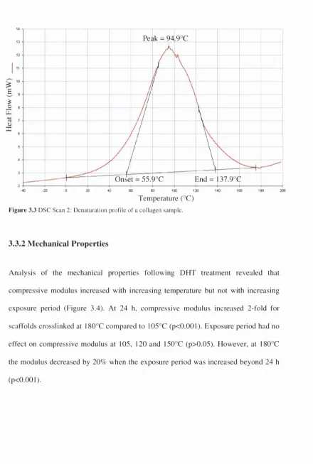
3.3.1 Differential Scanning C alorim etry... 63
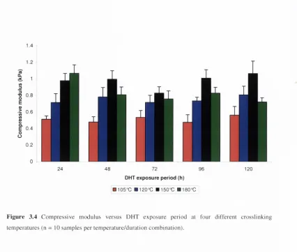
3.3.2 Mechanical Properties... 65
3.3.2 Crosslink Density... 67
3.3.3 D enaturation... 68
3.3.4 Multiple Linear Regression... 69
3.4 D iscussion... 72
3.5 C onclusion...77
4.
The effect of chemical crosslinking on the mechanical properties of collagen-
GAG scaffolds
4.1 Introduction...80
4.2 Materials and M ethod s... 82
4.2.1 Scaffold Fabrication... 82
4.2.2 Crosslinking...82
4.2.3 Mechanical Testing... 83
4.2.4 Statistical Analysis... 83
4.3 R e su lts... 84
4.3.1 ED AC C rosslinking... 84
4.3.2 GTA Crosslinking...85
4.3.3 Combined Crosslinking... 86
4.4 D iscussion... 87
4.5 C onclusion...911
5. The effect of crosslinking on the activity of osteoblasts within collagen-GAG
scaffolds
5.1 Introduction... 94
5.2.2 C ro s s lin k in g ...96
5.2.3 Cell C u ltu re & S e e d i n g ... 97
5 .2.4 A la m a r B lu e T M A n a l y s i s ... 98
5.2.5 H o e c h s t D N A A s s a y ... 98
5 .2.6 H i s t o l o g y ...99
5.2.7 Statistical A n a l y s i s ...99
5.3 R e s u l t s ... 99
5.3.1 M eta b o lic A c t i v i t y ...99
5.3.2 Cell N u m b e r ... 100
5.3.3 Cell D i s t r i b u t i o n ...103
5.4 D i s c u s s i o n ... 110
5.5 C o n c l u s i o n ... 1133
6. Discussion
6.1 C o lla g e n -G ly c o s a m in o g ly c a n Scaffolds and Tissue E n g i n e e r i n g ... 1166.2 Pore A r c h ite c tu r e ... 1 17 6.3 M e c h a n ic a l P r o p e r t i e s ... 120
6.4 C ro sslin k in g an d C e llu la r A c tiv ity ... 122
6.5 Future W o r k ... 125
6.6 C o n c l u s i o n s ... 1277
References...129
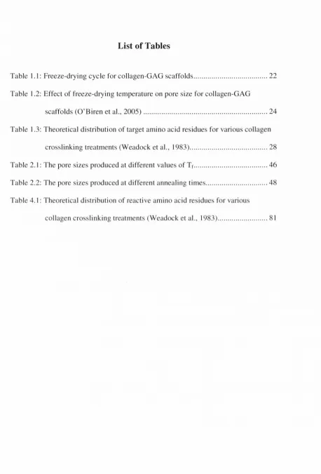
List of Tables
Table 1.1: Freeze-drying cycle for collagen-G A G scaffolds... 22 T able 1.2: Effect of freeze-drying tem perature on pore size for collagen-G A G
scaffolds (O ’Biren et al., 2 0 0 5 ) ...24 Table 1.3: Theoretical distribution of target am ino acid residues for various collagen
crosslinking treatm ents (W eadock et al., 1983)...28 Table 2.1: The pore sizes produced at different values o f Tf... 46 Table 2.2: The pore sizes produced at different annealing tim es... 48 Table 4.1: Theoretical distribution of reactive am ino acid residues for various
[image:10.534.47.505.33.708.2]List of Figures
F ig u re 1.1: C o lla g e n type I structure (G else et al., 2 0 0 3 ) ... 10
F ig u re 1.2: (A ) C o llag en ch ain (B ) C o llag en m o lecu le (C ) A m in o acid c o m p o sitio n o f type I c o llag en (B urgeson et al., 1976, A lb erts et al., 19 9 8 ) ... 1 1 F ig u re 1.3: C o lla g e n fibril structure, sh o w in g the b an d ed stru ctu re (G else e t al., 2 0 0 3 ) 12 F ig u re 1.4: S ch em atic o f ch o n d ro itin -6 -su lp h a te (H u an g and Y ang, 2 0 0 8 ) ...13
F ig u re 1.5: S caffo ld fabrication (H arley et al., 2 0 0 5 ) ...15
F ig u re 1.6: P h ase diag ram o f the freeze-d ry in g p ro cess (H arley et al., 2 0 0 5 )...16
F ig u re 1.7: P ro d u ct tem p eratu re during freezin g (S ahagian and G off, 1 9 9 6 )... 17
F ig u re 1.8: P ro d u ct tem p eratu res d u rin g fre e z in g ... 23
F ig u re 1.9: G lu tarald eh y d e crosslink form ation (L ee et al., 2 0 0 1 ) ...30
F ig u re 1.10: E D A C cro sslin k in g (L ee et al., 2 0 0 1 ) ...31
F ig u re 1.11: P h o to -cro sslin k in g o f cin n am a ted collag en (D ong et al., 2 0 0 5 ) ... 33
F ig u re 1.12: D H T cro sslin k in g (Y an n as and T o b o lsk y , 19 6 7 )...34
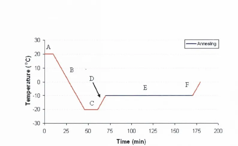
F ig u re 2.1: T im e -te m p e ratu re plot illu stratin g the stan d ard fre e ze-d ry in g c y c le and a lte ra tio n s to the final freezin g te m p e ra tu re ...41
F ig u re 2.2: T im e -te m p e ratu re plot fo r a stan d ard an n ealin g c y c l e ...4 2 F ig u re 2.3: M atlab an aly sis o f a stain ed s e c tio n ...44
F ig u re 2.4: T h e e ffe c t o f freezing te m p eratu re on pore .size... 46
F ig u re 2.5: D igital im ag es o f the stain ed scaffo ld sections ca p tu re d at 125x m a g n ific a tio n ...47
F ig u re 2.6: T h e e ffe c t o f heat an n ealin g on p o re s i z e ...48
F ig u re 2.7: D igital im ag es o f the stain ed scaffo ld sections cap tu re d at 125x m a g n ific a tio n ...49
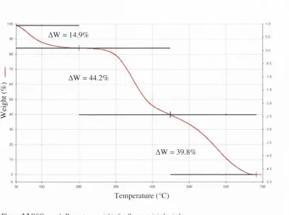
Figure 2.8: D TA analysis o f the CG suspension... 50
Figure 2.9: The effects o f m easurem ent technique and fabrication on pore s i z e ...54
Figure 3 .1: DSC scan of a collagen sam ple (A dapted from M entink et al, 2 0 0 2 )...60
Figure 3.2: DSC scan 1: Percentage weight o f collagen as it is h e a te d ...64
F igure 3.3: DSC Scan 2: D enaturation profile of a collagen s a m p le ... 65
F igure 3.4: C om pressive m odulus versus D H T exposure period at four different tem peratures... 66
F igure 3.5: Tensile m odulus versus D H T exposure period at fo u r different tem peratures... 67
Figure 3.6: C rosslink density versus D H T exposure period at fo u r different tem peratures... 68
Figure 3.7: D enaturation versus DHT exposure period at four different tem peratures... 69
Figure 3.8: Linear regressions o f moduli against crosslink density and d en a tu ra tio n ... 70
Figure 3.9: The relationship betw een tensile properties and d en a tu ratio n ... 71
Figure 3.10: Stress-strain curves show ing the effect o f denaturation on the m ode o f tensile fa ilu r e ...72
Figure 4.1: C om pressive m odulus vs. ED A C co n c en tratio n ...84
Figure 4.2: C om pressive m odulus vs. EDAC co n cen tratio n ...85
Figure 4.3: C om pressive m odulus versus G TA co n c en tratio n ...86
Figure 4.4: C om parison o f the optimal treatm ents and the com bined crosslinking tre a tm e n ts ... 87
Figure 5.2: M etabolic activity of M C 3T3 osteoblasts within the scaffolds at 1, 2 and 7 days as m easured using the A lam arBlue™ assay... 100 Figure 5.3: M C3T3 cell num ber within the scaffold at 1, 2 and 7 days m easured using H oechst DNA a s s a y ... 101 Figure 5.4: An assessm ent o f seeding efficiency on the various scaffold ty p e s 102 Figure 5.5: Proliferation o f M C 3T3 osteoblasts upon the various scaffold types .... 103 Figure 5.6: Spatial distribution o f M C 3T3 osteoblasts at the edge and centre of DFIT
crosslinked scaffolds (105°C , 24 h ) ... 104 Figure 5.7: Spatial distribution of M C3T3 osteoblasts at the edge and centre of DHT
crosslinked scaffolds (150°C, 48 h ) ... 105 Figure 5.8: Spatial distribution of M C3T3 osteoblasts at the edge and centre of EDAC crosslinked scaffolds (6 m m ol)...106 Figure 5.9: Spatial distribution of M C3T3 osteoblasts at the edge and centre of EDAC
crosslinked scaffolds (96 m m ol)... 107 Figure 5.10: Spatial distribution of M C3T3 o.steoblasts at the edge and centre o f GTA crosslinked scaffolds (0.125 m g )... 108 Figure 5.11: Spatial distribution o f M C3T3 osteoblasts at the edge and centre of
GTA +ED A C crosslinked scaffolds (96 mmol EDAC and 0.125 mg G TA) ... 109 Figure 6.1: The effect o f pore size on cell number, 2 days post .seeding...I 19
Acknowledgements
F irstly, I w o u ld like to th an k m y su p e rv iso r Prof. F erg al O ’B rien , fo r ta k in g m e on as a stu d e n t a n d g u id in g m y research o v e r the last fo u r years. I’m very g ra te fu l to hav e w o rk ed on this p ro je c t and b e lie v e I hav e b eco m e a b e tte r e n g in e e r d u e to F e rg a l’s a d v ice a n d su p p o rt. A d d itio n a lly , I ’d like to th an k P rof. P re n d e rg a st fo r a d v isin g m e w hen I w as c o n sid e rin g p o stg ra d u a te research and p o in tin g m e in F e rg a l’s d irectio n .
I hav e b een lucky to carry out th is w ork b etw een tw o in stitu tio n s, the R o y al C o lleg e o f S u rg eo n s in Irelan d and the T rin ity C en tre fo r B io en g in eerin g . I w o u ld like to th an k th e m em b ers o f sta ff at both these in stitu tio n s fo r m ak in g the last fo u r y ears en jo y ab le. In the an a to m y d e p a rtm e n t at R C S I; C live L ee, T o m , A lice, S in ead , S k an th a, C la ra g h , Jan e, P eter, V in n y , T erry , K atie, A m an d a, G arry and Ja c q u elin e. L ik e w ise , at T C D ; Jo a n G illen , S h e e n a B ro w n , P eter O ’R e illy , G e ra rd B y rn e and D anny K elly.
Kiva, Michael, Dave, Brianne, Jennifer, Stephen, Louise, Emma, Damien, Conor. Ciaran, John and Aidan.
Finally I would like to thank my fam ily. My parents, George and Maureen who have
guided me from day one. This would not be possible without their support and encouragement. M y siblings Stephen, George, Suzanne and my niece Rosella. Paul
Doyle also deserves special mention for helping me avoid library fines. I would also like to thank my close friends Tom, Dave, Johnny, Kev, W ill, Ronan, Riona & John.
I gratefully acknowledge grant support from the Science Foundation Ireland, under the President o f Ireland Young Researchers Award.
Nomenclature
3D 3-D im ensional
p TCP T ri-calcium Phosphate A N O V A A nalysis o f Variance atm A tm ospheric Pressure
CG C ollagen-G lycosam inoglycan C O2 C arbon D ioxide
C P C alcium Phosphate
AG Increase in M olar Free Energy AW Percentage C hange in W eight
DHT D ehydrotherm al
DNA D eoxyribonucleic Acid
DSC D ifferential Scanning C alorim etry DTA D ifferential Therm al Analysis ECM E xtra C ellular Matrix
EDAC I-E thyl-3-(3-D im ethyl A m inopropyl) C arbodiim ide FDA Food and Drug A dm inistration
FT-IR F ourier T ransform Infra-Red
GTA G lutaraldehyde
GAG G lycosam inoglycan
g Gram
HA H ydroxyapatite
Hyl H ydroxylysine
H& E H aem atoxylin and Eosin
hr H our
IR Infra-red
in Inch
k
R e-crystailisation RateL Liquid Phase
M C3T3 M ouse calvarial osteoblastic cell line
MGO M ethylglyoxai
m in M in u te
m T g ase M icro b ial tran sg lu tam in ase
N N ew to n
P P ressu re
P P assag e
Po S u rro u n d in g P ressure
P . V a p o u r P ressu re over a C u rv ed In terface P" N o rm al V a p o u r P ressure
PB S P h o sp h a te b u ffered saline PG A P o ly g ly c o lid e acid PL A P o ly la c tid e acid
P L G A P o ly -D L -la c tic -co -g ly c o lic acid
P P ro b ab ility
R C S I R oyal C o lle g e o f S urgeons in Ireland R U n iv ersal G as C onstant
''l, ^2 R adii o f C u rv atu re rpm R e v o lu tio n s p er M inuet S S o lid P h ase
SS S ta in le ss S teel T T e m p e ra tu re
Tc C ritic a l T em p eratu re
Teu E u tectic M eltin g T em perature Tg G lass T ra n sitio n T em perature Tf F re e z in g T em p eratu re TM T ra d e M ark
UV U ltra-V io let
V V a p o u r P hase V S p e c ific V o lu m e
V V o lu m e
W L F W illia m s-L a n d e ll-F e rry E tinn
W W eig h t
w /v W e ig h t to V o lu m e Solutioi
L L itre
m i M il l i l i t re (x 10'^) |il M i c r o l i t r e (x 10'^)
M ( o r m o l ) M o l a r
m m o l M i l i m o l a r ( x l O ’■)
m M e t r e
c m C e n t i m e t r e (x 10 ^) m m M i l l i m e t r e ( x l O ' ) | j m M i c r o m e t r e (x 10'^) n m N a n o m e t r e (x 10'^)
P a P a s c a l
k P a K il o p a s c a l ( x l O ’) M P a M e g a p a s c a l (x 10^)
m T o r r M i l l i t o r r ( x l O ’^)
W W a t t s
m W M i l l w a t t s ( x l 0 ‘^)
° D e g r e e s
° C D e g r e e s C e l s i u s
Publications and Presentations
Journal Articles:
H augh M .G ., Ja a sm a , M .J. an d O 'B rien F.J. (2008) T h e e ffe c t o f d eiiydrotiierm ai tre a tm e n t on the m ech an ical an d structural p roperties o f c o llag en -G A G scaffo ld s. J B io m e d M a te r R es A. In P ress.
B yrne E .M ., F arrell E., M cM ah o n L .A ., H augh M .G ., O 'B rien F. J., C am p b ell V .A ., P re n d e rg a st P.J. & O 'C o n n ell B.C. (2008) G ene ex p ressio n by m arro w stro m al c e lls in a p o ro u s c o lla g e n -g ly c o sam in o g ly ca n scaffold is affected by pore size and m ech an ical stim u latio n . J M a te r S ci M a te r M ed, 19, 3455-63.
T iern ey C .T ., H augh M .G ., L iedl J., M ulcahy F., H ayes B., Ja a sm a M .J. & O 'B rien F .J. (2 0 0 8 ) T h e e ffect o f c o llag en con cen tratio n and cro sslin k d en sity on b io lo g ic a l, stru ctu ral an d m ech an ical p ro p erties o f co llag en -G A G scaffo ld s fo r b o n e tissue en g in e e rin g . J o u rn a l o f the M e c h a n ic a l B eh a vio r o f B io m ed ica l M aterials. A c c e p te d fo r P u b licatio n .
The work contained in this thesis has been presented at the following
international and national conferences:
M u rp h y C .M ., H augh M .G . and O 'B rien F.J. (2008) The effect o f po re size on o ste o b la st activ ity in c o lla g e n -g ly co sam in o g ly can scaffolds. In: A b stra c ts fr o m the T issue E n g in e e rin g In te rn a tio n a l a n d R eg en era tive M edicine So ciety- E U C h a p te r M eetin g , P orto, P ortugal. A b stracts p u b lish ed in T issu e E n g in eerin g 14(5); 365.
O 'B rien F .J., H au g h M .G . and T iern ey C .M . (2(X)8) N ovel scaffo ld s fo r b o n e tissu e e n g in e e rin g . In: P ro ceed in g s o f 137th A n n u a l M eetin g a n d E xh ib itio n o f the M a teria ls, M e ta ls a n d M in e ra ls Society. N ew O rleans, LA: 177.
H augh M .G ., W alsh R .M . an d O 'B rien F.J. (2008) T he effect o f m o d ificatio n s to the fre e z e-d ry in g p ro c e ss on the arch itectu re o f co llag en -G A G scaffo ld s fo r use in tissu e - en g in e e rin g . In: P ro c e e d in g s o f the 14th A n n u a l C onference o f the S e ctio n o f B io e n g in e e rin g o f the R o ya l A c a d e m y o f M ed icin e in Ireland. - G. R eilly an d D .P. F itz P a tric k (eds) S lig o In stitu te o f T ech n o lo g y and U niversity C o lleg e D u b lin (IS B N
I 9 0 5 2 5 4 29 6): 89.
M cK iem an R., M urphy C .M ., Haugh M .G ., and O 'B rien F.J. (2008) G iutaraidehyde crossiinicing im proves the stiffness of coilagen-glycosam inoglycan scaffolds. In: P roceedings o f the 14th A nnual C onference o f the Section o f B ioengineering o f the Royal A cadem y o f M edicine in Ireland. - G. Reilly and D.P. FitzPatrick (eds) Sligo Institute of T echnology and U niversity C ollege D ublin (ISBN 1 905254 29 6): 101.
M urphy C .M ., Haugh M .G . and O'Brien F.J. (2008) The effect of pore size on osteoblast activity in coilagen-glycosam inoglycan scaffolds. In; Proceedings o f the 14th A nnual C onference o f the Section o f B ioengineering o f the Royal A cadem y o f M edicine in Ireland. - G. R eilly and D.P. FitzPatrick (eds) Sligo Institute o f Technology and U niversity C ollege Dublin (ISBN 1 905254 29 6): 87.
Haugh M .G ., W alsh R.M ., Jaasm a M.J. and O 'B rien F.J. (2007) The effect o f m odifications to the freeze-drying process on the architecture of collagen scaffolds for use in tissue engineering. 4th International C onference on Lyophilisation and Freeze Drying. Dublin 6.
Haugh M .G ., Jaasm a M.J. and O 'B rien F.J. (2007) D ehydrotherm al crosslinking o f collagen-G A G scaffolds. In: A bstracts fro m the Tissue Engineering International and Regenerative M edicine Society M eeting, London, UK. A bstracts published in Tissue Engineering 13(7): 91.
O 'B rien F.J., Haugh M .G ., Tierney C.M . and Jaasm a M.J. (2007) A designer coilagen- glycosam inoglycan scaffold for bone tissue engineering. In: P roceedings o f the 2nd International C onference on M echanics o f B iom aterials and Tissues, Lihue, Hawaii:
102.
Haugh M .G ., Jaasm a M.J. and O'Brien F.J. (2007) Dehydrotiierm ai crossiinl<ing of coiiagen-G A G scaffolds. In: Proceedings o f the I3th A nnual C onference o f the Section o f B ioengineering o f the Royal A cadem y o f M edicine in Ireland - F. B uchanan, N. D unne and J. Orr, (eds) Q ueen’s U niversity Belfast and University C ollege Dublin (ISBN 1 905254 18 0): 12.
A ltenbucher C., Haugh M .G ., and O 'Brien F.J. (2007) EDAC crosslinking of collagen-G A G scaffolds. In: Proceedings o f the 13th A nnual C onference o f the Section o f B ioengineering o f the Royal A cadem y o f M edicine in Ireland — F. B uchanan, N. D unne and J. Orr, (eds) Q ueen’s U niversity Belfast and U niversity C ollege Dublin (ISBN 1 905254 18 0): 88.
Byrne E.M ., Farrell E., M cM ahon L.A., Haugh M .G ., O 'B rien F.J., C am pbell V.A., Prendergast P.J. and O ’C onnell B.C. (2007) G ene expression by m arrow strom al cells in a porous collagen-G A G scaffold is affected by pore size and m echanical stim ulation. In: Proceedings o f the 13th A nnual C onference o f the Section o f B ioengineering o f the Royal Academ y o f M edicine in Ireland - F. B uchanan, N. D unne and J. Orr, (eds) Q u een ’s University Belfast and I ’niversity C ollege Dublin (ISB N 1 905254 18 0): 3.
Byrne E.M ., Farrell E., M cM ahon L.A., Haugh M .G ., O 'B rien F.J., C am pbell V.A., Prendergast P.J. and O ’C onnell B.C. (2006) G ene expression by m arrow strom al cells in a porous collagen-glycosam inoglycan scaffold is affected by pore size and m echanical stim ulation. In: Transactions o f 53rd M eeting o f the O rthopaedic Research Society, San Diego, CA: 296.
H augh M .G ., W alsh R.M ., Jaasm a M.J. and O'Brien F.J. (2006) The effect o f pore size, crosslinking and collagen content on the m echanical properties o f collagen-G A G scaffolds. In: A bstracts o f the 5th W orld C ongress o f Biom echanics, M unich, Germ any. A bstracts published in Journal o f B iom echanics 39(S216):6240.
W alsh R .M ., Ijaz Z „ H augh M .G ., Jaasm a M J . and O 'B rien F.J. (2 0 0 6 ) E ffect o f an n e a lin g on arc h ite c tu ra l and m ech an ical p ro p e rtie s o f fre e z e-d rie d c o lla g e n -G A G scaffo ld s. In: A b s tr a c t B o o k o f the T issu e E n g in e e rin g a n d R e g e n e ra tiv e M e d icin e In te rn a tio n a l S o ciety, R o tterd am , T h e N eth erlan d s: 147.
H augh M .G ., Ja a sm a M .J. an d O 'B rien F.J. (2 0 0 6 ) D e h y d ro th erm al cro sslin k in g o f co lla g e n -G A G scaffo ld s. In: R oyal C o lle g e o f S u rg eo n s in Irelan d R ese a rc h D ay 2006 B ook o f A b stracts.
H augh M .G ., Ja a sm a M .J. an d O 'B rien F.J. (2006) D eh y d ro th erm al cro sslin k in g o f co lla g e n -G A G sc affo ld s. In: P ro c e e d in g s o f the I2 th A n n u a l C o n feren ce o f the Sectio n o f B io e n g in e e rin g o f the R o y a l A c a d e m y o f M e d ic in e in Ire la n d — P. M cH u g h , D. O ’M a h o n e y an d D .P. F itzP atrick , (ed s) N U I G alw ay and U n iv ersity C o lleg e D ublin (IS B N 1 9 0 5 2 5 4 075): 33.
T iern ey C .M ., H augh M .G ., Ja a sm a M .J. an d O 'B rien F.J. (2 0 0 6 ) T h e in flu en ce o f co llag en a n d G A G c o n ten t on c e llu la r activ ity in sca ffo ld s fo r b o n e tissue en g in e e rin g . In: P ro c eed in g s o f the 12th A n n u a l C o n feren ce o f the Section o f B io e n g in e e rin g o f the R o ya l A c a d e m y o f M ed ic in e in Ire la n d - P. M cH u g h , D. O 'M a h o n e y an d D .P. F itzP atrick , (eds) N U I G alw ay an d U n iv ersity C o lle g e D ublin (IS B N 1 9 0 5 2 5 4 075): 54.
T iern ey C .M ., H augh M .G ., Ja a sm a M .J. an d O ’B rien F.J. (2 0 0 6 ) T h e b io lo g ical and m ech an ical c h a ra c te ristic s o f several c o lla g e n -G A G sc a ffo ld s fo r b o n e tissue en g in e e rin g . S y m p o siu m on the A n a to m y o f T issue E n g in e e rin g a t the W in ter M eetin g o f the A n a to m ic a l S o c ie ty o f G rea t B rita in a n d Irela n d , O x fo rd , U K . A b stracts p u b lish e d in J o u r n a l o f A n a to m y 209(4): 568.
T iern ey C .M ., H augh M .G ., W alsh R .M , Ja a sm a M .J. and O 'B rien , F .J. (2005) C o llag en -G A G sc a ffo ld s fo r th e d e v e lo p m e n t o f b o n e graft su b stitu tes. P ro ceed in g s o f the N o rth ern Ir e la n d B io m e d ic a l E n g in e e rin g Society, 25'^ A n n iv e r s a r y S p rin g M eeting, B elfast, N o rth e rn Ireland: 13.
W alsh R .M ., H augh M .G ., T ie rn e y C .M ., Ja a sm a M .J. and O 'B rien , F.J. (2005) C o llag en scaffo ld s fo r use as b o n e g raft su b stitu tes: D esign and fa b ric a tio n o f scaffo ld s to p ro m o te c e ll a ttach m en t, p ro liferatio n and bone fo rm atio n . In: R oyal C o lleg e o f S u rg eo n s in Irelan d R esearch D ay 2005 B o o k o f A b stracts.
Chapter 1.
Introduction and Literature Review
Contents
1.1 O verview ...2
1.2 Scaffolds for Tissue Engineering... 5
1.1 Overview
R e p a ir is the sta n d a rd m a m m a lia n response to significant organ injury. It is typically
ch aracterised by c lo su re o f the w o u n d thro u g h contraction and scar form atio n .
G en erally this m e a n s that the organ in question loses m ost o r all o f its functionality.
R eg e n e ra tio n on the o th e r h a n d is characterised by restoration o f the norm al structure
and function o f the org an (Y a n n a s, 2001). T h e p articular response o f an o rg a n to
injury is d e p e n d a n t on the lo cation and extent o f the d a m a g e as well as the organ in
question. T h e c o n s e q u e n c e s o f healing by repair range from physical d isfiguration to a
c o m p le te loss o f o rg a n functionality. D ue to these deficiencies, it is e v id en t that the
induction o f reg en eratio n is favourable to repair. T h e re are several a p p ro a c h e s to
induce regeneration in cases o f severe organ trauma.
T ra n sp la n ta tio n is the m ost widely used treatm ent to o v e rc o m e the d eficien cies
asso ciated with tissue repair. D uring transplantation, healthy tissue is re m o v e d fro m a
d o n o r site an d s u b se q u e n tly grafted to the injured site in o rd er to induce regeneration.
A u to g raftin g is tran sp lan tatio n using healthy tissue harvested from the patient,
w h e re a s allografting utilises tissue taken from a separate donor. D esp ite the
w id e sp re a d use o f transplantation, there are several sh o rtco m in g s o f this treatm ent.
W ith autografting, a longer o p e ra tio n is needed to rem ove tissue from the d o n o r site;
this harv estin g puts e x tra stress on the patient and can cau se co m p lic a tio n s such as
tissue m orbidity at the d o n o r site (G ian n o u d is et al., 2005). As m any patients
requiring grafts are elderly, the quality and quantity o f tissue available for g rafting can
also be an issue. W ith allografting, there is the risk o f im m u n e response an d the
tra n sm issio n o f viral d iseases and infections from the donor. In addition the n u m b e r o f
s uitable d o n o rs a v ailab le is a n o th e r lim iting factor (L anza et al., 1997). P ro c e ssin g o f
allo g raft tissu e re d u c e s the risk o f in fectio n but can sig n ifican tly w eak en the b io lo g ical and m e c h a n ic al p ro p e rtie s initially p resen t in the tissue.
In som e cases p e rm a n e n t p ro sth eses m ay b e u sed to re sto re partial fu n c tio n to the in ju red organ. C o m m o n ex a m p le s o f th is are artificial jo in t re p lacem en ts, h e a rt v a lv e s and p acem ak ers (N elissen , 2003, P o n te fra c t et al., 20 0 4 , C h an an d C a rd all, 2006). A s they are fa b ric a ted from m a te ria ls th a t are b io lo g ically inert, th e im m u n e re sp o n se asso ciated w ith allo g ra ftin g is a v o id ed . H o w ev er, th e u n n atu ral or artificial n a tu re o f p ro sth eses c a u se s several p ro b lem s. A rtificial hip p ro sth e se s are c o m m o n ly m ad e from m etallic a llo y s such as titan iu m , th e se m a te ria ls are several tim es stiffe r than the tissu e they rep lace. T h is c a u ses stre ss sh ie ld in g and su b se q u e n t reso rp tio n o f the su rro u n d in g b o n e lead in g to fa ilu re o f the p ro sth esis (L ew is et al., 1984). In ad d itio n , even w ith b io lo g ically inert m a te ria ls th ere m ay an in flam m ato ry re sp o n se resu ltin g in sc a r tissue en c a p su la tio n , p re v e n tin g restitu tio n o f n o rm al tissue stru ctu re (M ik o s et al., 1998). T h e se d e fic ie n c ies an d the lack o f b io lo g ical fu n ctio n c lassify p e rm a n e n t p ro sth eses as an in fe rio r tre a tm e n t c o m p a re d to re g e n e ratio n o f the in ju red organ.
stim u li to the cell-se e d ed scaffo ld are also c o m m o n ly used to e n c o u ra g e c e lls to form tissu e on the scaffo ld in vitro. T issu e e n g in e e rin g has found initial c lin ical su c c e ss in sev eral areas in clu d in g skin, nerve and b la d d e r (Y an n as et al., 1989, C h a m b e rla in et al., 1998, A tala et al., 2006).
In o u r lab o rato ry w e use a co m p o site sca ffo ld that is fab ricated fro m c o llag en and a g ly c o sa m in o g ly c a n (G A G ) as a b asis fo r tissu e en g in eerin g . T h is scaffo ld is cu rren tly b e in g used in a n u m b e r o f ti.ssue e n g in eerin g ap p licatio n s. C o llag en has receiv ed in creasin g a tten tio n o v er the p ast few y ears o w in g to its e x c e lle n t b io c o m p atib ility , d e g ra d a tio n in to p h y sio lo g ical e n d -p ro d u cts an d su itab le in teractio n w ith c e lls and o th e r m a c ro m o lecu les (G e ig e r et al., 2003). G A G s are co m m o n co n stitu e n ts o f cell su rfaces and e x tra c e llu la r m atrices. T he first g en eratio n o f c o lla g e n -G A G scaffo ld s w as d e v e lo p e d fo r skin reg en eratio n in p atien ts w ith m assiv e sk in loss by lo an n is Y an n as at M IT (Y a n n a s an d B urke, 1980, Y an n as et al., 1980, D ag alak is et al., 1980). T h e se sc a ffo ld s hav e also been in v estig ated fo r th e ir p o ten tial use in induced re g e n e ratio n o f p erip h eral nerves and a rtic u la r ca rtila g e (C h am b erlain et al., 1998, L ee et al., 2001).
P rev io u s w ork has sh o w n that internal arc h ite c tu re and the m ech an ical p ro p e rtie s o f sca ffo ld s fo r tissu e en g in e e rin g can have a sig n ific a n t in flu en ce on the activ ity o f cells w ith in th em (O 'B rien e t al., 20 0 5 , L ee et al., 20 0 1 , B y rn e et al., 2008). T he aim o f this th e sis is to d e v e lo p a series o f novel C G sc affo ld s w ith a ran g e o f stru ctu ral and m ech an ical p ro p e rtie s an d to d e te rm in e the effe c ts o f these p ro p e rtie s on c e llu la r b eh av io u r. T h is w ill allow the p ro d u ctio n o f a series o f c h a ra c terise d scaffo ld v arian ts
w h ich can be a d a p te d fo r sp ecific tissu e en g in e e rin g a p p lic a tio n s o r u sed to ex p an d
o u r u n d e rsta n d in g o f the in teractio n s b etw een scaffo ld p ro p erties an d c e llu la r activity.
1.2 Scaffolds for Tissue Engineering
O n e o f the p rin c ip a l m e th o d s in tissu e e n g in e e rin g in v o lv es the u se o f a po ro u s
sc a ffo ld to su p p o rt an d guide sy n th e sis o f a 3D tissu e or o rg an (S a c h lo s and
C z e m u sz k a , 2 0 0 3 ). T h e sca ffo ld itse lf is th e re fo re a very im p o rtan t a sp e c t o f tissue
e n g in e e rin g . It has been p ro p o sed that a sca ffo ld m ust fulfil a n u m b e r o f key criteria
(H u tm a c h e r, 2001):
• B io c o m p a tib ility
• B io d e g ra d a b ility
• M e ch an ical p ro p e rtie s
• 3 -D P o ro u s a rc h itectu re
B io c o m p a tib ility is a c o n c e p t that is sim p le in p rin c ip le but c o m p lic a te d in p ractice. It
is ty p ic a lly d e fin e d as “ the ab ility o f a m aterial to p erfo rm w ith an a p p ro p ria te host
re sp o n se in a sp ecific a p p lic a tio n ” (W illiam s, 1986). T h e b ro a d n e ss o f th is d efin itio n
red u ces its u se fu ln ess so m ew h at and in p ractice, the term is w id ely u sed to d escrib e
m aterials w h ich are n o n -to x ic w hen im p lan ted into the body. In a d d itio n , a
b io c o m p a tib le scaffo ld should also su stain cell fu n ctio n an d p h e n o ty p e if it is to be
su ccessfu l as a tissu e e n g in e e rin g .scaffold. B io d eg rad ab ility is a n o th e r im p o rtan t
asp ect o f sc a ffo ld p e rfo rm an ce. T h e scaffo ld m ust be d e sig n e d to d e g ra d e into
b io c o m p a tib le p ro d u c ts th ro u g h o u t the h e alin g p ro cess, e v e n tu a lly leav in g rep aired or
m ust also last long enough to support the activity of the cells as they carry out the
rem odelling process.
The m echanical properties of the scaffold are im portant for several reasons. The
scaffold must have suitable characteristics in order to facilitate in vitro handling and w ithstand the in vivo environm ent. It is often stated that scaffolds need to have m echanical properties resem bling that of native tissue (Luo et al., 2007). However,
standard treatm ents for load bearing tissues use supports such as fixation and sutures
to bear m echanical loading during healing and rehabilitation (K oob, 2002,
Finkem eier, 2002). A dditionally, it is worth noting that a mixture o f bone m arrow and
dem ineralised bone m atrix with the consistency o f sand has been successfully used to
treat non-union bone fractures, while even m echanically durable treatm ents such as
cortical bone grafts require the use of fixation (Tiedem an et al., 1995, Finkem eier,
2002
).In addition, the m echanical properties o f the scaffold can direct cellular activity and
further determ ine the functionality o f a tissue-engineered construct (E ngler et al.,
2004a, E ngler et al., 2006, E ngler et al., 2004b, Yeung et al., 2005). In a study by
E ngler et al. (2006), the differentiation of m esenchym al stem cells (M SC s) was show n to be dependant on the m echanical properties of the substrate they w ere seeded
upon. N eurogenic, m yogenic and osteogenic m arkers were found on substrates with
Y oung’s m oduli o f I, II and 34 kPa respectively. It has also been noted that
m echanical properties can influence the interaction betw een cells and the scaffold
(Torres et al., 2000, Lee et al., 2001). C hondrocytes and fibroblasts were shown to
contract the scaffolds they w ere seeded upon; the level o f contraction was show n to be
dependant on the m echanical properties o f the scaffolds (Torres et al., 2000, Lee et al.,
2001). C ontraction causes several problem s, the pore volum e and perm eability o f the
scaffold is reduced, limiting cellular proliferation. In addition, in vivo contraction
would cause problem s at the interface betw een the scaffold and the host tissue. It is
therefore essential that a scaffold has appropriate properties to limit cell-m ediated
contraction.
The pore architecture of .scaffolds for use in tissue engineering has been show n to
have a significant effect on physical properties, cellular activity and va.scularisation
(W ake et al., 1994, N ehrer et al., 1997b, T suruga et al., 1997, Z eltinger et al., 2001,
O 'B rien et al., 2005, O'Brien et al., 2007). It has been hypothesised that the pore
diam eter must be large enough to allow infiltration o f the cells tow ards the centre o f
the scaffold, whilst being small enough to present sufficient ligand density for cellular
attachm ent (Y annas, 2001, O 'Brien et al., 2005). The optim al pore size is dependant
on both the cell type and scaffold m aterial. Upon collagen scaffolds with a range o f
pore sizes (95-150 |jm ), O ’Brien et al. (2(X)5) found that osteoblast attachm ent
increased with decreasing pore size, with optimal attachm ent upon scaffolds with a
m ean pore size o f 95 ^m . Z eltinger et al. (2001) report that upon PLA scaffolds
endothelial cells prefer pores in a range of 30-80 jam. Furtherm ore, it is com m only
reported that large pores (>I(X) pm ) are required for bone form ation and
vascularisation (Tsuruga et al., 1997, Byrne et al., 2008, C ao et al., 2006). In addition,
the pore size also determ ines perm eability, which in turn influences the diffusion of
nutrients and waste products within the scaffolds as well as the stim ulus applied by
A s the ex act re q u ire m e n ts are d ep en d an t on the specific ap p licatio n , m any m aterials have been p ro p o se d as scaffo ld s su itab le fo r tissue en g in eerin g . T h e re are th ree m ajo r
cla ssific a tio n s o f m aterials th at hav e been used as scaffo ld s fo r tissu e en g in eerin g : c e ram ics, sy n th e tic p o ly m ers and natural polym ers. T h ese c la ssific a tio n s are
d isc u sse d in the fo llo w in g sections.
1.2.1 Ceramic Scaffolds
C e ra m ic s are in o rg an ic n o n -m etallic c o m p o u n d s; they are c ry sta llin e in n atu re and are fo rm e d from a co m b in a tio n o f m etallic an d non-m etallic elem en ts. T h ey ty p ically hav e a high stiffn e ss but are very brittle. B ecause o f th e ir high stiffn e ss, ceram ic sc affo ld s are m o st c o m m o n ly u sed in b o n e tissue en g in eerin g . T h e m ost c o m m o n ce ra m ic s used are calciu m p h o sp h ate (C P ), tri-calciu m p h o sp h ate (P -T C P ) and h y d ro x y ap atite (H A ) (B a rra le t et al., 2002, C h u et al., 2002, P o rte r et al., 2004). H A is a n atural c o n stitu e n t o f b o n e and has been sh o w n to be b io c o m p a tib le and o ste o c o n d u ctiv e. B oth (3-TCP and H A are h ighly b io co m p atib le. T h ey d iffe r h o w ev er, in the b io lo g ical re sp o n se cre a te d at the host site. P orous P-T C P is re m o v e d from the im p lan t site as b o n e g ro w s into the scaffold w hile HA is m ore p e rm an en t (G ia n n o u d is et al., 2005). In g en eral, c e ram ic scaffo ld s have been fo u n d to be b rittle and th ere is a lack o f co n tro l o f the d e g ra d a tio n rate, w hich is generally very slow .
1.2.2 Synthetic Polymer Scaffolds
u sin g sy n th e tic p o ly m e rs is the fact that they can b e m a n u fa c tu red w ith a w ide ran g e o f m e c h a n ic al p ro p e rtie s and a rc h itectu res. T h e fu n d a m e n ta l p ro b lem a sso c ia te d w ith the use o f sy n th e tic p o ly m ers is th e ir d e g ra d a tio n p ro d u cts, acid ity and alco h o l co n ten t. In p a rtic u la r, sca ffo ld acid ity has been im p lic a te d in a c c e lera tin g the d e g ra d a tio n o f the sc a ffo ld and c a u sin g a p ro n o u n c e d in fla m m a to ry re sp o n se in the su rro u n d in g tissu e le ad in g to an in h ib itio n o f tissu e fo rm atio n (F isc h e r an d R ed d i, 2003).
1.2.3 Natural Polymer Scaffolds
N atu ral p o ly m e rs in clu d e c o llag en , c h ito san , gelatin , silk fib rin , g ly c o sa m in o g ly c a n s an d elastin (P ark et al., 2002, N a z a ro v et al., 20 0 4 , D aw so n et al., 2008). T h ese m aterials are fo u n d n atu rally in the ex tra c e llu la r m atrix (E C M ) o f m any tissu es and as such c o n ta in m any su rface lig an d s an d p e p tid e s ap p ro p ria te fo r c e llu la r a tta c h m e n t and c e ll-sc a ffo ld in te ractio n s (H arley and G ib so n , 2 0 0 8 ). A s b io lo g ic a l m a te ria ls they have e x c e lle n t b io co m p a tib ility an d n o n -to x ic d e g ra d a tio n pro d u cts. T h e sh o rtc o m in g o f natural p o ly m e rs is th e ir p o o r m ech an ical p ro p erties, w hich are not su ffic ie n t fo r high stren g th a p p lic a tio n s un less th e p o ly m e r is c h e m ic a lly treated. In th is stu d y a c o m p o site o f tw o natural p o ly m ers, co lla g e n an d c h o n d ro itin su lp h ate, is used as a scaffold.
1.3 C ollagen-G A G Scaffolds
1.3.1 Collagen and Glycosaminoglycans
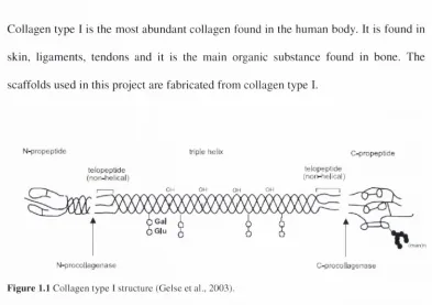
Collagen type I is the most abundant collagen found in the human body. It is found in skin, ligaments, tendons and it is the main organic substance found in bone. The scaffolds used in this project are fabricated from collagen type I.
N -p ro p e p tid e tn p io liclix C -p ro p e p tra e
te lo p e p lid e le lo p e p lid e
(n o n -h e lic a l) (n o i)-fie|ica l)
Om OH OH 1
G al G lu
F ig u re 1.1 C o lla g e n ty p e 1 stru ctu re (G else et al., 2003).
Collagen type I is a heterotrimer (Figure I . I ), meaning it is a triple helix that consists o f two a I chains and an a2 chain. The a2 chain has a slightly different amino acid sequence compared to the a I chains. Collagen type I triple helices are 300nm long and contain approximately 3000 amino acid residues. Each of the three a-chains within the molecule forms an extended left-handed helix with a pitch of 18 amino acids per turn (Hofmann et al., 1978). The three chains, staggered by one residue relative to each other, are supercoiled around a central axis in a right-handed manner to form the triple helix (Fraser et al., 1979). The polypeptide chains have a repeating unit (Gly-X-Y), with a glycine residue in every third position in the polypeptide chain. The plane o f each peptide bond is positioned perpendicular to the axis o f the helix .so that the carbonyl groups are pointed in a direction where they form .strong interchain hydrogen bonds with other chains in the molecule (Devlin, 2006). The triple helix is formed such that glycine, the smallest amino acid, is positioned at the centre of the helix and the more bulky side chains of other amino acids occupy the outer positions.
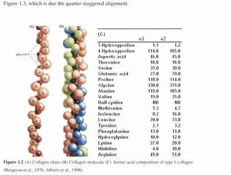
[image:33.534.91.484.70.347.2]T h is allo w s a c lo se p a c k in g alo n g th e ce n tre o f the m o lecu le as show n in F ig u re 1.2 B (G e lse et a!., 2 0 0 3 ). T h e X and Y p o sitio n s are m ost c o m m o n ly o c c u p ie d by the a m in o acids p ro lin e an d h y d ro x y p ro lin e , resp ectiv ely . A b rea k d o w n o f the a m in o a c id c o n te n t o f type I c o lla g e n is sh o w n in F ig u re 1.2 C. T he n o n -h elical reg io n s at the en d o f th e co llag en m o le c u le are called telo p e p tid e s; th ese are in v o lv ed in in te rm o le c u la r cro sslin k in g o f c o lla g e n m o lecu les. T h e p ro p e p tid e s are im p o rtan t in the fo rm a tio n o f the co llag en m o lecu les. O n ce trip le h elic e s are fo rm ed , th ey g ro u p to g e th e r to form c o llag en fibrils. T h e se fib rils have a d istin c tiv e b a n d e d a p p earan ce illu strated in F ig u re 1.3, w h ich is d u e the q u a rte r-sta g g ere d alig n m en t.
F ig u re 1.2 (A) C o lla g e n c h ain (B) C o lla g e n (B u rg e so n et al., 1976, A lb erts et al., 1998).
3 -H y d io x y |)io tin e 1.1 1.2
4 -H y d io x y |)io jliie 114.0 105.0
A s p e itic a c id 46.0 45.0
T Iu e o n in e 18.0 18.0
S e rin e 35.0 30.0
G liitoniic a c id 77.0 70.0
P to liiie 118.0 114.0
G lycine 330.0 331.0
A ldiiiiie 119.0 105.0
V .iliiie 19.0 35.0
H.ilf-cystine ND ND
M e tliioiiine 5.3 4.7
Iso leiiciiie 8.2 16.0
L e u c in e 20.0 33.0
T y io sin e 2.1 3.2
P h e n y l <ilonine 13.0 11.0
H ydro x y ly sin e 10.0 12.0
L ysine 27.0 20.0
H istidine 4.0 10.0
A ixjinine 49.0 51.0
[image:34.534.54.520.292.645.2]3 0 0 nm •1C nm
fTTrrnnTT
monorrers
3_E
3 -E
□ c
□ c
innrmnntiinnti
c o l l a g e n fibril6 5 - 6 7 n m
Figure 1.3 C ollagen fibril structure, showing the banded structure (Gelse et al., 20()3).
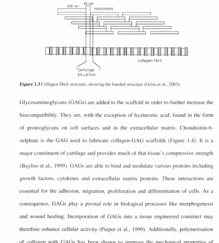
G l y c o s a m in o g ly c a n s ( G A G s ) are a d d e d to the scaffold in o rd e r to further in crease the b io co m p atib ility . T h e y are, with the e x c e p tio n o f h yaluronic acid, fo u n d in the form o f p r o te o g ly c a n s on cell surfaces and in the e x tra c e llu lar matrix. C hond ro itin -6 - s u lp h ate is the G A G used to fabricate c o lla g e n -G A G scaffolds (Figure 1.4). It is a m a jo r co n stitu en t o f cartilage and p ro v id es m u ch o f that t is s u e ’s c o m p re ssiv e strength (B ay liss et al., 1999). G A G s are able to bin d and m o d u late various proteins including g ro w th factors, cy to k in e s and ex tra c e llu lar m atrix proteins. T h ese interactions are e ssential fo r the adh esio n , m igration, p roliferation and differentiation o f cells. A s a c o n s e q u e n c e , G A G s play a pivotal role in biological p ro cesses like m o rp h o g e n e s is and w o u n d healing. In c orporation o f G A G s into a tissue e n g in e e re d construct m ay therefore e n h a n c e c ellu lar activity (P ie p e r et al., 1999). A dditionally, p o ly m erisatio n o f collagen with G A G s has been sh o w n to im p ro v e the m echanical p ro p erties o f c o llag en ( Y a n n a s et al., 1975).
[image:35.534.58.490.94.574.2]COOH
HO OH
' O
OH HN CH3
F ig u re 1.4 S ch em atic o f c h o n d ro itin -6 -s u lp h a te (H u an g and Y ang, 2008).
1.3.2 Collagen-GAG Scaffolds
1.3.3 Fabrication of Collagen-GAG Scaffolds
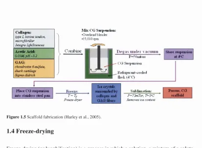
C o lla g e n -G A G sc a ffo ld s are m an u factu red using a freeze-d ry in g (o r ly o p h ilisatio n ) p ro cess (D ag alak is et al., 1980, O 'B rien et al., 2004, O 'B rien et al., 2005). P rio r to fre e z e-d ry in g , co lla g e n an d G A G are m ix ed to g eth er w ith acetic acid to p ro d u c e a co lla g e n -G A G su sp e n sio n . T h is su spension is then p laced into a fre e z e-d ry e r w hich c o o ls it in a c o n tro lle d m an n er. A s the slurry freezes the co llag en -G A G so lu te is lo c a lise d b etw e e n th e g ro w in g ice cry stals, fo rm in g a c o n tin u o u s, in terp en etratin g n etw o rk o f ice and so lu te. S u b lim atio n o f the ice cry stals leads to the fo rm atio n o f a h ig h ly p o ro u s sp o n g e. T h e po re size o f the scaffold m irro rs the size o f the ice c ry stals fo rm e d d u rin g fre e z in g an d is th erefo re affected by the d etails o f this process. O ’B rien e t al. (2004) d e v e lo p e d a m eth o d fo r co o lin g the scaffo ld s at a co n stan t rate to give a h o m o g e n e o u s sca ffo ld w ith eq u iax ed pores. T he effect o f freeze-d ry in g on the pore arc h itectu re o f C G sca ffo ld s is d iscu ssed in detail in S ectio n 1.4 and C h ap ter 2. A fter fre e z e-d ry in g , C G sca ffo ld s are cro sslin k ed in o rd e r to en h an ce th e ir m ech an ical p ro p e rtie s an d red u ce th e ir d e g rad atio n rate. T he stan d ard cro sslin k in g m eth o d is d eh y d ro th e rm a l tre a tm e n t (D H T ), although several d ifferen t treatm en ts have been u tilised in th e literatu re (L ee et al., 2001, H arley et al., 2007, P iep er et al., 2000). T h is to p ic is d isc u sse d in fu rth e r d etail in Section 1.5 and C h a p te rs 3 & 4.
C'oUsi{«i:
type /, bovine tendon, microjibnllar Integra lAfeSciencee
Acflic Acid:
a05M, p H -3.2
GAG:
chondroitin 6suljate, shark cartilage Sigma-Aldrich
P lact CG siispeiisiou iiito stainless steel pan
C G Suc|>nL<:ioii; •O verhead blen d er •1 5 ,000 rpm
t ’oinb iiie T)e«:is iiiiilfi v :in iiiiii P=50iufoii
CO Siispejisiou Refiisei niit-cooled Hask(-l’C)
Freeze;
Freeze-dryer
Ice ciyslals Sim ortuled by
collnseii and GAG fibers
Siiblimarioii;
Store sii<peusioii at -l°C
P=75mTor, T^OC Removes ico content
Porous, CG scaffold
F ig u re 1.5 S caffo ld fa b ric atio n (H arley et al., 2005).
1.4 Freeze-drying
F re e z e -d ry in g (o r ly o p h ilisa tio n ) is a p ro cess in w h ich a so lu tio n , a m ix tu re o f a so lu te and a so lv en t, is fro zen and then dried. It is p rim arily a m ean s o f in c re a sin g the stab ility o f m a te ria ls fo r long term sto rag e and is mo.st c o m m o n ly used in the p h arm aceu tical an d b io lo g ical in d u stries. T h e free z e-d ry in g p ro cess has several ad v a n ta g e s o v e r o th e r d ry in g m e th o d s, the m ain on e b ein g th at it can be ap p lied to m aterials, such as p ro te in s, w hich m ay be affe c ted by the ad d itio n o f heat. T h e m ajo r d isa d v a n ta g e is th a t it is an e n erg y in ten siv e p ro cess. In this stu d y w e use the freeze- d ry in g p ro cess to fa b ric a te p o ro u s c o llag en scaffo ld s; co n se q u e n tly an u n d e rsta n d in g o f the p ro cess is n eed ed to c o n siste n tly p ro d u ce h o m o g e n e o u s scaffo ld s.
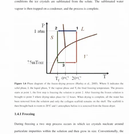
T he fre e z e-d ry in g p ro cess can be sp lit into tw o parts: freezin g and dry in g . D u rin g
[image:38.534.48.461.45.349.2]c o n d itio n s the ice crystals are su b lim ated from the solute. T h e s u b lim a te d w ater v a p o u r is then trapped on a condenser, and the process is com plete.
1 atm
"5
iii
T
oit
f
Figure 1.6 Phase diagram o f the freeze-drying priKess (H arley et al., 2005). W here S indicates the solid phase, L the liquid phase, V the vapour phase and Tf the final freezing tem perature. The process starts at point I, the first step is freezing the solution to point 2. After freezing the frozen solution is brought to point 3 w here drying takes place for 12 hours. When drying is com plete, all the w ater has been removed from the solution and only the collagen scaffold rem ains on the shelf. The scaffold is then brought back to room to 20°C and 1 atm osphere before it is removed from the freeze-dryer.
1.4.1 Freezing
D u rin g freezing a tw o step process occurs in w hich ice crystals nucleate a ro u n d particulate im purities within the solution and then grow in size. C o n v en tio n ally , the structure o f the ice crystals f o rm e d during freezing is only o f significance b e c a u se o f its effect on drying; h o w e v e r, w h en prod u cin g scaffolds for tissue en g in e e rin g it has fu rth er significance as the ice crystal structure will m irror the pore structure o f the scaffold produced. T h e im portant structural characteristics are pore size, shape, distribution and interconnectivity.
[image:39.534.47.497.91.560.2]Before describing the freezing process it is important that two words are defined: cooling and freezing. Cooling is a reduction in temperature, whereas freezing is an abrupt conversion o f a solution into a mixture o f ice and solute concentrate. Cooling below freezing temperature without freezing is called supercooling or subcooling (Biopharma, 2005). The cooling rate is an important aspect o f the freezing cycle; traditionally these rates have been described in an unscientific manner, i.e. slow or fast. A better description is the rate at which the shelf or product is cooled per unit time; shelf temperature is most commonly used to control the process. Typically cooling rates o f less than l°C /m in are considered slow and anything above (but usually in the region o f 20-50°C/min) is considered fast (Biopharma, 2005).
i
Q) Q_ E .0)□°c
WaterAB Sl B' fe te r nudeaJon
C freezing point depression to Tt C D'
freeze-concenlralion CD crystal gnowti
DE sensibie iieat of ice
Water Sugar '
solution
T im e ►
Figure 1.7 Product temperature during freezing (Sahagian and Goff, 19%).
o f ice cry sta ls th ro u g h o u t the liquid v o lu m e, takes place. T he p re se n c e o f the so lu te
p a rticles p ro m o tes n u c le a tio n ; e x p la in in g w hy the su g ar so lu tio n n u c le a te s at a h ig h e r
tem p e ra tu re than p u re w ater. S u p erco o lin g is a m etastab le state w h ich is an a lo g o u s to
an a c tiv atio n en erg y n ece ssa ry fo r the n u cleatio n p ro cess (S ah ag ian and G o ff, 1996).
N u cleatio n su b se q u e n tly ta k es place from point B to C (B ' to C ) . H o w ev er, on ly a
fractio n o f fre e z e-a b le w ater c ry sta llise s du rin g n u cleatio n , as c ry sta llisa tio n is
e x o th e rm ic (S e arles, 2 0 0 4 ). N o te th at the Tf o f the su g a r so lu tio n is lo w er than th e Tf
o f w ater, this fre ezin g p o in t d e p ressio n is due to the p resen ce o f so lu tes.
C ry stal g ro w th an d fre e z e co n c e n tra tio n tak e place from C to D. T h e cry sta ls grow as
the rem ain in g w a te r in the n u cleated so lu tio n is frozen. T h e partially fro zen m ix tu re
will not cool until all o f the fre e z ea b le w ater has cry stallised . W ith the su g a r so lu tio n ,
freeze c o n c e n tra tio n ta k es p lace from C to D'. A s w a te r freezes in the so lu tio n , the
co n c e n tra tio n o f the so lu te in the liquid phase increa.ses. This p h en o m e n o n is term ed
freeze co n c e n tra tio n . F reeze co n c e n tra tio n low ers the freezin g te m p e ra tu re and
increases the v isco sity o f the so lu tio n . T he increase in vi.scosity o f the so lu tio n , c au sed
by lo w er te m p e ra tu re s and freeze co n cen tratio n , red u ces the m o b ility o f w ater
m o lecu les an d h in d ers crystal grow th.
T he m o rp h o lo g y o f ice cry sta ls in the fro zen p ro d u ct is p rim a rily d e p e n d e n t on
n u cleatio n . In p a rtic u la r, ice cry stal size has been sh o w n to be in v ersely p ro p o rtio n al
to the ex ten t o f su p e rc o o lin g at n u cleatio n (S earles et al., 2001). N u c le a tio n is, in turn,
a ffected by the rate o f co o lin g an d the nature o f p articu late im p u rities w ith in the
so lution. A s n u c le a tio n is affe c ted by en v iro n m en tal p articu lates, it is th e re fo re not
co o lin g w ill a lso h a v e an effect on th e cry stal fo rm atio n d u rin g freezin g . F ast rates o f
co o lin g h av e a te n d e n c y to p ro d u c e m any sm all ice cry stals. T h e se c ry sta ls m ay not
be c o n tin u o u s, b u t they are g en e ra lly h o m o g e n e o u sly d istrib u te d th ro u g h o u t the
fro zen so lu tio n . A slo w rate o f fre e z in g w ill resu lt in a m ore c o n n e c te d ice cry stal
stru c tu re w ith la rg e r cry sta ls (B io p h a rm a , 2005).
1.4.2 D rying
D ry in g is th e se c o n d step in the fre e z e-d ry in g p ro c e ss and it in v o lv es the rem o v al o f
w a te r fro m th e fro z e n solution. T ra d itio n a lly , d ry in g can be split into p rim ary and
se c o n d a ry d ry in g , w h ere p rim ary re fers to the rem oval o f w a te r by su b lim a tio n , the
c o n v e rsio n o f a so lid d irectly into a v ap o u r, an d seco n d ary d ry in g is the rem o v al o f
b o u n d w a te r by d e so rp tio n . A s the stan d ard cro sslin k in g treatm en t fo r the c o llag en -
G A G s c a ffo ld s (D H T ) rem o v es b o u n d w a te r w hen it fo rm s c ro sslin k s, th ere is no
n e e d fo r se c o n d ary d ry in g in our fre e z e -d ry in g cycles.
F ig u re 1.6 sh o w s h o w the phase o f w a te r is related to its tem p eratu re and p ressu re.
F rom th is c h a rt it is c le a r th at ice can be co n v e rte d d irectly to v ap o u r by ad d in g heat
at low p ressu re s. T h is phase c h an g e req u ires a large am o u n t o f energy, a p p ro x im ately
28 0 0 J to c o n v e rt 1 g o f ice to v a p o u r (B io p h arm a, 2005). H av in g frozen the so lution
and c re a te d a so lid , th e p ressu re is re d u ced and heat is ap p lied to su b lim ate the ice to a
v apour. T h e v a p o u r is then trap p ed on the conden.ser as ice. B ecau se su b lim atio n is
e n d o th e rm ic , d ry in g is su sta in e d by a p p ly in g h eat to the so lution. H o w ev er, this heat
m ust be a p p lie d w ith care as ex c e ssiv e heat input m ay m elt o r co llap se th e scaffo ld
(d e sc rib e d later). In c o n trast, ap p ly in g in su fficien t heat w ill result in the solution
su b lim atio n to cease. T he en d p o in t o f the drying p ro c e ss is a c c ep ted to be the
c o n v e rg e n c e o f sh e lf and p ro d u ct tem p eratu re, i.e. w hen ad d in g heat in c re a se s the
te m p eratu re o f the so lution rath er than fu ellin g su b lim atio n (B io p h arm a, 2005).
In o rd e r to trap w a te r v ap o u r on the co n d en ser, a p ressu re d ifferen ce is n eed ed
betw een the ice in terface in the p ro d u ct and the co ld su rface o f the co n d en ser.
A d d itio n ally , a p ressu re g rad ien t betw een the w ater m o lecu les and the su rro u n d in g
a tm o sp h ere is also n ecessary and this is p ro v id ed by the vacu u m . It is kn o w n that all
m aterials ex ert a v a p o u r pressu re and this pressu re is related to te m p eratu re; so we
m ay d efin e the d riv in g force fo r su b lim atio n as the d ifferen ce in v a p o u r p ressu re
b etw een the sam p le and the c o n d en ser. H ow ever, th ese co n c e p ts o f su b lim atio n do
not tak e into acco u n t resistance to the v ap o u r flow as it m ig rates from the d ry in g
so lu tio n to the condenser. R esistan ces to v ap o u r flow in clu d e m ech an ical im p ed an ces
by b affles, in terco n n ectio n s and v alv es in the sy stem and im p ed an ces re.sulting from
interactio n s betw een v apour m o lecu les and the in n er vial su rface and stopper. T h ese
resistan ces have to b e taken into ac c o u n t w hen c h o o sin g the c o n d e n se r te m p eratu re o f
a cy cle. T y p ically 15° b elow the p ro d u ct te m p eratu re is su fficien t to o v e r co m e any
resistan ce to v a p o u r flow (B io p h arm a, 2005).
In dry in g a n u m b e r o f p ro c e ssin g d e fects o ccu r w hich n eed to be av o id ed . T h ese
include:
• E u tectic m elting. T h is is d e fin e d as the m e ltin g o f a eu tectic so lid (region o f a
frozen m aterial o u tsid e o f the ‘pu re ic e ’ fractio n ). W h en u n d er v acu u m , this