http://dx.doi.org/10.4236/cs.2016.78138
Finite Element Analysis (FEA) for the
Beam-Column Joint Subjected to Cyclic
Loading Was Performed Using ANSYS
B. Venkatesan1, R. Ilangovan2, P. Jayabalan3, N. Mahendran4, N. Sakthieswaran51Department of Civil Engineering, University VOC College of Engineering, Thoothukudi, India 2Department of Civil Engineering, University College of Engineering, Dindigul, India
3Deptartment of Civil Engineering, National Institute of Technology, Tiruchirappalli, India 4Deptartment of Civil Engineering, PSNA College of Engineering and Technology, Dindigul, India 5Department of Civil Engineering, Anna University Regional Campus, Tirunelveli, India
Received 13 April 2016; accepted 10 May 2016; published 15 June 2016
Copyright © 2016 by authors and Scientific Research Publishing Inc.
This work is licensed under the Creative Commons Attribution International License (CC BY).
http://creativecommons.org/licenses/by/4.0/
Abstract
This paper analyses the seismic performance of exterior beam-column joints strengthened with unconventional reinforcement detailing. The beam-column joint specimens were tested with re-verse cyclic loading applied at the beam end. The samples were divided into two groups based on the joint reinforcement detailing. The first group (Group A) of three non-ductility specimens had joint detailing in accordance with the construction code of practice in India IS456-2000, and the second group (Group B) of three ductility specimens had joint reinforcement detailed as per IS13920-1993, with similar axial load cases as the first group. The experimental studies are prov-en with the analytical studies carried out by finite elemprov-ent models using ANSYS. The results show that the hysteresis simulation is satisfactory for both un-strengthened and ferrocement streng-thened specimens. Furthermore, when ferrocement strengthening is employed, the strengstreng-thened beam-column joints exhibit better structural performance than the un-strengthened specimens of about 31.56% and 38.98 for DD-T1 and DD-T2 respectively. The analytical shear strength predic-tions were in line with the test results reported in the literature, thus adding confidence to the va-lidity of the proposed models.
Keywords
B. Venkatesan et al.
1. Introduction
Beam-column joints are an important part of reinforced concrete (RC) moment resisting frames in earthquake- prone areas. The cross sections of beams and columns that are close to the joints in RC structures are critical, and under the impacts of strong earthquake waves, they are exposed to large bending moments and shear forces. The moment resistance frame in the beam-column joint controls the transmission of force to the structure. In RC frames designed for gravity loads, the design check for joints is not normal. In recent seismic attacks, the joints collapsed due to shear failure. The moment resistance frame should be sufficient in terms of the overall sizes at the preliminary design, and the joint should be provided with necessary reinforcement. For structures in low and medium seismic zones, the seismic effect should be considered. Reinforcement of the structure as per the gen-eral code of practice may not meet the present seismic codal provision. A beam-column joint is structurally less efficient when subjected to large lateral loads, which include strong winds, earthquakes and explosions. For structures in these areas, high percentages of traverse hoops in the joint core are required to achieve high strength, stiffness and ductility under cyclic loading. [1] conducted experimental and analytical studies using ANSYS, and additional cross bracing reinforcement improved the seismic performance. [2] used continuous SIMCON jackets to increase the confinement of column lap splice in the joint region. [3] carried out nonlinear dynamic analysis by hysteretic response of the exterior beam-column joint with stiffness degradation without the punch effect and with low and high punch effects. [4] conducted two groups of different joint designs of rein-forcement details: joints reinforced with traditional steel rebar and another group of prefabricated cage system (PCS). Their study concluded that the PCS reinforced joints had slightly higher strength. [5][6] found that reha-bilitated specimens with GFRP and CFRP strengthened specimen exhibited an improved load carrying capacity and a higher rate of stiffness than the virgin specimens. [7] studied the exterior beam-column joint specimen sign per IS456-2000 and IS13920-1993 and tested the specimens under push-pull load. Then, the specimen de-signed per IS456-2000 was retrofitted using GFRP-AFRP/AFRP-GFRP hybrid fibre sheet, and the performance was compared to the reference specimen. The study concluded that the specimen designed using IS13920-1993 showed a 10% - 11% higher load carrying capacity compared to the IS456-2000 specimen. [8] investigated the effect of different strengthening methods of exterior joint ends under various axial loads. Existing reinforced concrete (RC) columns may be structurally deficient due to a variety of causes such as improper transverse re-inforcement and insufficient load carrying capacity flaws in structural design. Carbon or glass fibre reinforced polymer (FRP) confinement can be effectively used for strengthening deficient RC columns. Researchers have attempted to investigate the experimental behaviour of GFRP wrapped small scale square RC columns with varying corner radii. Three columns were unwrapped and designated as the control specimens. Three columns each with corner radii equivalent to a cover of 25 mm were wrapped with one and two layers of GFRP, respec-tively. The GFRP wrapped columns underwent higher axial displacement to gain higher compressive strength over the control column. [9]-[11] found that increasing the number of layers of the GFRP wrapping for RC columns under axial load achieved higher maximum strength and larger maximum strain. However, the strength increase is not linearly proportional to the number of GFRP layers. [12]-[14] found that FRP rehabilitation schemes exhibit remarkable enhancement in terms of the load carrying capacity of the specimen. Beam-column joints were made according to the existing practice and were tested under cyclic lateral loading to calculate the effect of using high performance steel fibre reinforced concrete instead of conventional concrete in the joint re-gion. Qualities such as the ultimate strength, the energy dissipation capacity, the ductility, and the joint stiffness of the control concrete specimens were analysed compared to those containing different amounts of brass-coated fibres or hook steel fibres. According to IS13920-1993 and IS456-2000, the performances of exterior joint as-semblages were analysed using FEA software and compared to the retrofitted specimen.
According to ACI549, ferrocement is a thin walled section less than 25 mm thick containing closely spaced small diameter wire mesh and cement mortar. In this study, ferrocement laminates with two different Vf of 1.72 and 3.44 and with welded and woven mesh with 2:1 CM for the cross section of 500 mm × 125 mm × 25 mm thick laminate were casted. The properties of the welded and woven meshes used in the ferrocement laminate were diameters of 1.42 mm and 0.82 mm and openings of 16 mm and 4.5 mm, with cross-sectional areas of 1.58 mm2 and 0.52 mm2, ultimate strengths of 482.24 N/mm2 and 692.36 N/mm2 and moduli of elasticity of 0.71 × 10⁵ N/mm2 and 1.36 × 10⁵ N/mm2, respectively.
2. RC Beam-Column Joint
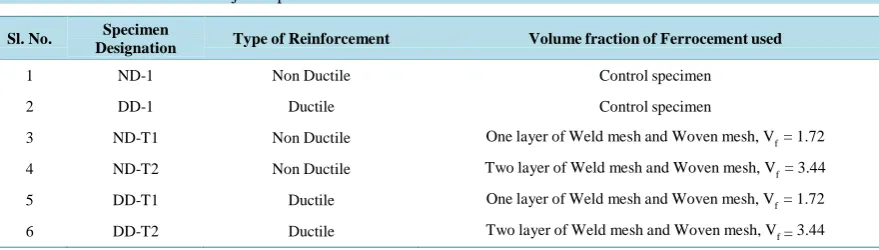
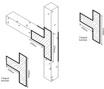
Six specimens of external beam-column joints with cross sections for both beams and columns of 230 mm × 230 mm with a beam of 1.25 m span and a column 2 m high were casted. The reinforcement detailing for three of the specimens is according to IS456-2000 (non-ductile), and the remaining three specimens are per IS13920-1993 (ductile). In the non-ductile specimens, the reinforcement provided are 4 - 12 mm ϕ bar and 8 mm ϕ stirrups at a spacing of 150 mm c/c uniformly for the beam and column. The reinforcement provided for the ductile speci-mens are 4 - 12 mm ϕ bar and 8 mm ϕ stirrups at a spacing of 100 mm and 75 mm in the non-anchorage and anchorage zones, respectively, in the beam and column. The reinforcement details are shown in Figure 1 and Figure 2. The details of ferrocement laminate strengthening for the beam-column joint is shown in Table 1.
2.1. Wrapping of Ferrocement Laminates
The surface of the beam-column joints and the ferrocement laminates are cleaned and prepared prior to bonding the laminates to the joint. COROCRETIN IHL-18 is used for the bonding of the ferrocement laminate with the beam-column joint. A 2 mm thick bonding liner has been provided constantly for all of the retrofitted specimens. The details of the ferrocement laminates wrapping pattern are shown in Figure 3.
Table 1. Details of beam column joint specimens.
Sl. No. Specimen
Designation Type of Reinforcement Volume fraction of Ferrocement used
1 ND-1 Non Ductile Control specimen
2 DD-1 Ductile Control specimen
3 ND-T1 Non Ductile One layer of Weld mesh and Woven mesh, Vf = 1.72
4 ND-T2 Non Ductile Two layer of Weld mesh and Woven mesh, Vf = 3.44
5 DD-T1 Ductile One layer of Weld mesh and Woven mesh, Vf = 1.72
[image:3.595.92.532.297.422.2]6 DD-T2 Ductile Two layer of Weld mesh and Woven mesh, Vf = 3.44
B. Venkatesan et al.
Figure 2. Reinforcement details for ductile joint.
[image:4.595.137.483.415.708.2]2.2. Test Set-Up
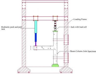
A hydraulic jack of 500 kN capacity was used for the axial positioning of the column but did not restrain the di-rection of the axial load of the column. To hold the specimen in place, 20% of the axial load, i.e., 100 kN, was applied to the column. A 500 kN capacity hydraulic push and pull jack was used to produce the reverse cyclic load in the beam portion. A point load was applied at 50 mm from the free end of the beam, and the reverse in-crement was noted by applying the load at a 5 mm displacement for push and pull throughout the testing. A li-near variable differential transducer with a range of ±75 mm was used to measure the displacement at the load-ing point. Figure 4 shows the diagrammatic representation of the test setup is shown in Figure 4.
2.3. Strength, Stiffness and Energy Dissipation for the Specimens
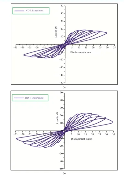
The experimental and the analytical values of strength, stiffness and energy dissipation for the specimens ND-1, DD-1, ND-T1, DD-T1, ND-T2 and DD-T2 are in graph. The hysteresis behaviours of the specimens are shown
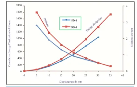
in Figure 5. The ND-1 and DD-1 specimens failed at 30 mm and 35 mm displacements and collective loads of
1031.67 kN and 1752.57 kN, respectively. Cumulative energy dissipation and stiffness vs displacement is shown
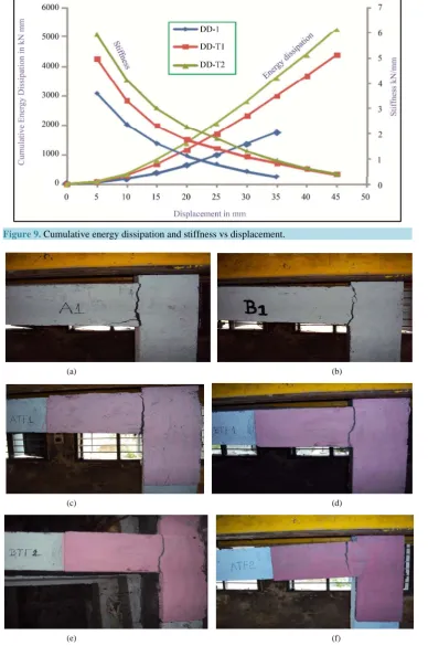
in Figure 6. The ferrocement retrofitted specimens ND-T1, DD-T1, ND-T2 and DD-T2 failed at 40 mm, 45 mm,
[image:5.595.113.505.408.709.2]45 mm and 45 mm displacements and collective loads of 2897.48 kN∙mm, 4369.96 kN∙mm, 3979.94 kN∙mm and 5241.91 kN∙mm, respectively. Hysteresis behavior of ferrocement retrofitted specimen as shown in Figure 7. The total collective energy dissipation of ND-T1 and ND-T2 increased by 64% and 75% compared to ND-1. Furthermore, the increase in the collective energy dissipation for the member retrofitted with ferrocement (DD-1) compared to the non-ductile specimen (ND-1) indicates that ferrocement can be used as a substitute for ductile detailing. Cumulative energy dissipation and stiffness vs displacement is shown in Figure 8. The increase in the total collective energy dissipation for DD-T1 compared to DD-1 is 60%, showing that ferrocement with a vo-lume fraction of 3.44 performs better than ferrocement with a vovo-lume fraction of 1.72. Again, the increase in the total collective energy dissipation shows that the ferrocement retrofitting is an efficient strategy for retrofitting existing ductile detailed structures if the seismic zone is upgraded. Cumulative energy dissipation and stiffness
B. Venkatesan et al.
(a)
[image:6.595.103.508.74.646.2](b)
Figure 5. (a) Hysteresis behavior of control specimen ND-1. (b) Hysteresis behavior of con-trol specimen DD-1.
Figure 6. Cumulative energy dissipation and stiffness vs displacement.
2.4. Crack Pattern of Control Specimen
All of the samples showed failure in the beam portion. Furthermore, yielding of the steel was observed at the point of failure. Strain gauges were bonded in the beam portion. However, the strain gauges deboned at the ul-timate load and the allowable deflection. The crack patterns of the tested specimens are shown in Figures 10(a)-(f).
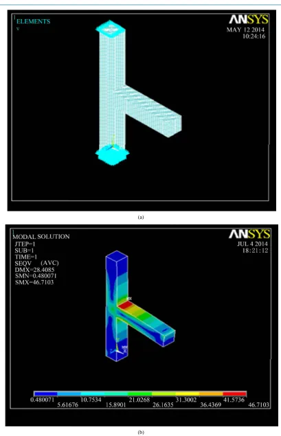
3. Numerical Analysis (ANSYS)
Finite element analysis (FEA) for the beam-column joint subjected to cyclic loading was performed using ANSYS. Further experimental results are studied in compression with analytical results for beam-column joints. The concrete has been modelled using an eight-node solid element (SOLID 65) capable of handling crushing in compression, creep, cracking in tension and plasticity. An iterative solution is essential because the characteris-tic of the adapted element is non-linear. The compressive strength of the concrete (fck) is 34.23 MPa, the tensile strength of the concrete (ft) is 3.5 MPa, and the elastic modulus (Es) is 25850 MPa. The reinforcement steel was modelled with a series of two-node link elements (LINK 8). The properties pertaining to the link included an initial yield stress of 448 MPa. The adhesive layer was structured using 3D isotropic elements (SOLID 45). The elasticity of the material property modulus is (Es) 1500 MPa.
The boundary conditions were simulated with the precision in the test set-up of the horizontal and vertical re-straints, representing a pin connection applied at the top and bottom of the column. The vertical displacements were provided to simulate the cyclic load condition at the end of the beam. The load conditions were used in the test. The top-most columns were subjected to a constant load of 100 kN. The vertical displacement at the free end of the beam was applied using a slowly increasing monotonic method. The results were recorded for every 5 mm vertical displacement up to failure. Figure 11(b) shows the deflected shape of the model
B. Venkatesan et al.
(a)
(b)
(d)
Figure 7. (a) Hysteresis behavior of ferrocement retrofitted specimen ND-T1. (b) Hysteresis behavior of ferrocement retrofitted specimen DD-T1. (c) Hysteresis be-havior of ferrocement retrofitted specimen ND-T2. (d) Hysteresis bebe-havior of
[image:9.595.156.464.82.295.2]fer-rocement retrofitted specimen DD-T2.
Figure 8. Cumulative energy dissipation and stiffness vs displacement.
kN∙mm, respectively, in the experiment and 989.34 kN∙mm, 2733.67 kN∙mm and 3947.47 kN∙mm, respectively, using ANSYS. The stiffness observed were 3.0 kN/mm to 0.5 kN/mm, 3.94 kN/mm to 0.65 kN/mm, and 4.8 kN/mm to 0.48 kN/mm, respectively, in the experiment and 2.60 kN/mm to 0.48 kN/mm, 3.4 kN/mm to 0.4 kN/mm and 4.3 kN/mm to 0.45 kN/mm, respectively, using ANSYS.
[image:9.595.162.466.348.535.2]B. Venkatesan et al.
Figure 9. Cumulative energy dissipation and stiffness vs displacement.
(a) (b)
(c) (d)
(e) (f)
Figure 10. (a) Crack pattern of tested beam column joint specimen ND1. (b) Crack pattern of tested beam column joint specimen DD1. (c) Crack pattern of tested beam column joint specimen ND-T1. (d) Crack pattern of tested beam column joint specimen DD-T1. (e) Crack pattern of tested beam column
(a)
[image:11.595.107.517.71.707.2](b)
B. Venkatesan et al.
(a)
(b)
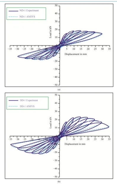
Figure 12. (a) Hysteresis behavior of specimen ND-1 (Experiment vs ANSYS Comparison). (b)
[image:12.595.113.509.73.698.2](a)
[image:13.595.138.484.72.696.2](b)
Figure 13. (a) Cumulative Energy dissipation and stiffness vs Displacement for non-ductile
B. Venkatesan et al.
(a)
[image:14.595.91.523.77.694.2](b)
experimental values in Figures 12-17.
4. Conclusions
• The strength initial stiffness and energy dissipation of ductile and non-ductile detailed beam-column joints DD-1 and ND-1 showed higher strengths of 16.67%, 8.30% respectively.
• The ferrocement for retrofitting increased the energy dissipation capacity and is more efficient for reinforced beam-column joints in seismic regions. In addition, the non-ductile reinforced beam-column joint can be vi-talized by strengthening using ferrocement laminates.
[image:15.595.136.489.232.399.2]• The non-ductile specimen ND-1, compared with the ferrocement-strengthened ND-T1 and ND-T2, showed increased strength, stiffness, and energy dissipation capacity by 33.11%, 45.40% and 23.8% and 37.5%, 64.39% and 74.07%, respectively.
Figure 15. Cumulative energy dissipation and stiffness vs displacement.
B. Venkatesan et al.
[image:16.595.103.532.81.379.2](b)
Figure 16. (a) Hysteresis behavior of specimen DD-T1 (Experiment vs ANSYS). (b) Hysteresis
behavior of specimen DD-T2 (Experiment vs ANSYS).
Figure 17. Cumulative energy dissipation and stiffness vs displacement.
• The ductile specimen DD-1, compared with the ferrocement-strengthened DD-T1 and DD-T2, showed in-creased strength, stiffness, and energy dissipation capacity of 31.56%, 46.50% and 27.27% and 38.98%, 59.89% and 66.56%, respectively.
[image:16.595.133.494.412.655.2]References
[1] Bindhu, K.R. and Jaya, K.P. (2012) Strength and Behavior of Exterior Beam Column Joints with Diagonal cross Brac-ing Bars. Asian Journal of Civil EngineerBrac-ing (BuildBrac-ing and HousBrac-ing), 11, 397-410.
[2] Dogan, E. and Neven, K. (2003) Seismic Retrofit with Continuous Slurry Infiltrated Mat Concrete Jackets. ACI Struc-tural Journal, 100, 713-722.
[3] Maria, J.F. and Chris, G.K. (2014) Influence of Pinching Effect of Exterior Joints on the Seismic Behaviour of RC Frames. Earthquake and Structure, 6, 89-110. http://dx.doi.org/10.12989/eas.2014.6.1.089
[4] Matthew, J.F. and Halil, S. (2011) Behavior of Exterior Reinforced Concrete Beam-Column Joints Including a New Reinforcement. Structural Engineering and Mechanics, 40, 867-883. http://dx.doi.org/10.12989/sem.2011.40.6.867
[5] Ramakrishna, R.V.S. and Ravindra, V. (2012) Experimental Investigation on Rehabilitation of Reinforced Cement Concrete Interior Beam-Column Joints Using CFRP and GFRP Sheets. International Journal of Engineering Science and Technology, 4, 874-881.
[6] Hamid, N.H., Hadi, N.D. and Ghani, K.D. (2013) Retrofitting of Beam-Column Joint Using CFRP and Steel Plate. In-ternational Journal of Civil, Architectural Science and Engineering, 7, 300-305.
[7] Robert, R.S. and Arulraj, P.G. (2010) Experimental Investigation on Behavior of Reinforced Concrete Beam Column Joints Retrofitted with GFRP-AFRP Hybrid Wrapping. International Journal of Civil and Structural Engineering, 1, 245-253.
[8] Umut, A. and Stefano, P. (2002) Assessment and Design Procedure for the Seismic Retrofit of Reinforced Concrete Beam-Column Joints Using FRP Composite B Structures Subjected to Seismic Forces. Journal of Composites for Con-struction, 16, 21-34.
[9] Sushil, S., Urmil, V.D. and Himat, S. (2013) FRP Wrapping for RC Columns with Varying Corner Radii. Procedia Engineering, 51, 220-229. http://dx.doi.org/10.1016/j.proeng.2013.01.031
[10] Pradip, S., Rajesh, A. and Menon, D. (2007) Design of RC Beam Column Joints under Seismic Loading. Journal of Structural Engineering, 33, 449-457.
[11] Senthilkumar, E., Murugesan, A. and Thirugnanam, G.S. (2010) Experimental Study on Behavior of Retrofitted with FRP Wrapped RC Beam-Column Exterior Joints Subjected to Cyclic Loading. International Journal of Civil and Structural Engineering, 1, 64-79.
[12] Said, A.M., Nehdi, M.L. and Kehew, A.E. (2004) Use of FRP for RC Frame in Seismic Zones, Evaluation of FRP Beam Column Joints Rehabilitation Techniques. Applied Composite Materials, 11, 205-226.
http://dx.doi.org/10.1023/B:ACMA.0000035462.41572.7a
[13] Jamal, S.M. and Nabeela, A. (2005) Lateral Load Response of High Performance Fibre Reinforced Concrete Beam Column Joints. Construction and Building Material, 19, 500-508.
http://dx.doi.org/10.1016/j.conbuildmat.2005.01.007
[14] Shannag, M.J., Barakat, S. and Abdul-kareem, M. (2000) Cyclic Behavior of HPFRC Repaired Reinforced Concrete Interior Beam-Column Joints. Materials and Structures, 35, 348-356. http://dx.doi.org/10.1007/BF02483154
[15] IS13920-1993 (2002) Indian Standard Ductile Detailing of Reinforced Concrete Structures Subjected to Seismic Forces. Bureau of Indian Standards, New Delhi.