ί||ΙΙ1|β;
« sp
¡ »g» "lá ipüC'lllaiilli'ffijjljliiJl^Ml.
RliKSw
mP
lmm 4mm
I S H M SSI
1«
ïvÊSm
Λ Β ¡ a j i . ' i - l ' e i ' i i i í' V!M*
Joint Nuclear Research Center Geel Establishment Belgium
Central Bureau for Nuclear Measurements (CBNM)
i.\ í ¡tlJ JUiiltfH .(IH I r H »ft ' ni ■ * *nSv I In'f Text presented at the
f i l l
ÌÉii '
"Colloque International sur l'Electronique Nucléaire", , Paris (France) November 2527, 1963
spira»
¡ili
This document was Atomic Energy Community
mm
ι» iji.KT ' . ¿i\.í5 ?! 4rL líSlífiijUBl? Ρ ! T< 'tf'HW3 »tf Iw'UJer'l'wiiS'i'TÎsl. 'iii' if prepared under the sponsorship of t h e Commission of the European
' < ^ R A T O M ) .
Neither the EURATOM Commission, its contractors nor any person acting on their behalf
Tifei
1° Make any warranty or representation, express or implied, with respect to the accuracy, completeness, or usefulness of the information contained in this document, or t h a t the use disclosed in this document m a y not »IH'' ' Γ Π | Μ Ι |
-of any information, apparatus, method, or process
«if
infringe privately owned rights; or frí^rFí loffia? ¡t'twHìft,!2° ·— Assume any liability with respect to the use of, or for damages resulting from t h e use of any information, apparatus, method or process disclosed in this document.
E U R 4 9 1 . e
A NANOSECOND TIME CODER W I T H GREAT ANALYSIS RANGE FOR TIME-OF-FLIGHT E X P E R I M E N T S by P. KLOPF, H. MEYER. W. STUBER, H. VERELST.
European Atomic Energy Community - EURATOM. Joint Nuclear Research Center.
Geel Establishment (Belgium).
Central Bureau for Nuclear Measurements (CBNM).
Text presented at the „Colloque International sur l'Electronique Nucléaire,,. Paris (France), November 25-27, 1963.
Brussels, December 1963 - pages 20 - figures 10.
A first version of a nanosecond time coder for „on line,, and „off-line,, time-of-flight analysis was built with the following main characteristics :
smallest channel width, /\t min of one nanosecond; maximum possible channel
number for a time accuracy of one channel, greater 213 channels ; a regulation system was developed to increase this value up to about 21S. An overall differential accuracy of i 0.15 nanosecond was reached for input pulses with a risetime up to 20 nanoseconds and a dynamic range of 10 max. The development results show the possibility of decreasing the smallest channel width down to 0.25 nanosecond for reliable function.
E U R 4 9 1 . e
A NANOSECOND TIME CODER W I T H GREAT ANALYSIS RANGE FOR TIME-OF-FLIGHT E X P E R I M E N T S bv P. KLOPF, H. MEYER, W. STUBER, H. VERELST.
European Atomic Energy Community - EURATOM. Joint Nuclear Research Center.
Geel Establishment (Belgium).
Central Bureau for Nuclear Measurements (CBNM).
Text presented at the „Colloque International sur l'Electronique Nucléaire,,. Paris (France), November 25-27, 1963.
Brussels, December 1963 - pages 20 - figures 10.
A first version of a nanosecond time coder for „on line,, and „off-line,, time-of-flight analysis was built with the following main characteristics :
smallest channel width, ¿\l min of one nanosecond ; maximum possible channel
The planned „multiple storage per analysis cycle,, and a prebuffer store under development will probably allow a storage time down to 128 nano-seconds for an event to be analysed.
The unit is a combination of a chronotron type system \vith the classical Argonne system. Active elements used are tunnel diodes and transistors. Lay-out of equipment will be described and discussed.
The planned „multiple storage per analysis cycle,, and a prebuffer store under development will probably allow a storage time down to 128 nano-seconds for an event to be analysed.
E U R
4 9 1 . e
EUROPEAN ATOMIC ENERGY COMMUNITY - EURATOM
A NANOSECOND TIME CODER WITH
GREAT ANALYSIS RANGE
FOR TIME-OF-FLIGHT EXPERIMENTS
by
P. KLOPF, H. MEYER, W. STUBER, H. VERELST
1963
Joint Nuclear Research Center Geel Establishment - Belgium
Central Bureau for Nuclear Measurements (CBNM)
Text presented at the
C O N T E N T S
INTRODUCTION 5
FUNCTION AND LAY-OUT 6
OUTPUT CONNECTIONS S
CHARACTERISTICS S
POSSIBLE IMPROVEMENTS !>
RESUMING REMARKS 10
KEY TO THE FIGURES
Fig. 1 — General block diagram of the time coder 13
Fig. 2 — More detailed block diagram of the first version of the time coder
realized 14
Fig. 3 — Time conditions at the scaler gate for the stop function 15
Fig. 4 — Characteristics of the nanosecond time coder 16
Fig. 5 — Frequency of the unregulated cable oscillator vs. temperature . . . 17
Fig. 6 — Propagation delay variation of input unit vs. input pulse shape. . . 17
Fig. 7 ■— Differential accuracy of time analysis (a) ; accuracy of ring propagation
delay (b) 18
Fig. 8 — Time coder, first version (provisional) 19
Fig. 9 — Cable oscillator with start and stop gates 19
A NANOSECOND TIME CODER WITH GREAT
ANALYSIS RANGE FOR TIME-OF-FLIGHT EXPERIMENTS
SUMMARY
A first version of a nanosecond time coder for "on line" and "off-line" time-of-flight analysis was built with the following main characteristics :
smallest channel width, Δ t min of one nanosecond; maximum possible channel number for a time
accuracy of one channel, greater 2'3 channels ; a regulation system was developed to increase this value
up to about 218. An overall differential accuracy of ± 0.15 nanosecond was reached for input pulses
with a risetime up to 20 nanoseconds and a dynamic range of 10 max. The development results show the possibility of decreasing the smallest channel width down to 0.25 nanosecond for reliable function. The planned "multiple storage per analysis cycle" and a prebuffer store under development will probably allow a storage time down to 128 nanoseconds for an event to be analvsed.
The unit is a combination of a chronotron type system with the classical Argonne system. Active elements used are tunnel diodes and transistors. Lay-out of equipment will be described and discussed.
INTRODUCTION
The aim of our work was to realize a time coder for flight time analysis with a best time resolution, i.e. smallest channel width of one nanosecond, an analysis range of more than ten thousand channels and high stability for long time running experiments, especially for the mea surement of neutron energy spectra. Such a unit can be helpful, especially, for future work in high resolution time-of-flight analysis, with pulsed sources of sufficiently small burst width and where burst rate, intensity of neutrons and suitable energy threshold values will allow flight paths long enough to have a great dynamic range, also for acceptable measuring times.
The system realized can be used for the experimental program of the BCMN of Euratom with its pulsed neutron sources. For this program several main instrumentation systems are planned or developed, as for instance 4096-channel on-line analysis systems, including time coders with 10 nanosecond smallest channel width which are realized by developmental contracts with two industrial firms. Another system, especially for complex off-line analysis of flight times in a wide range and/or multiparameter spectra is under development in our laboratories. The developed time coder shall be used together with this handling system, but also diiectly with memory com puter systems of 256 to 4,096 channels.
For a time coder with the mentioned characteristics, a direct application of chronotron or vernier chronotron systems (1) is not practical and very probably not to realize because of the great analysis range needed. Time expanding technics are not suitable because of insufficient stability and accuracy for long time running experiments and great analysis ranges. (Examples for such technics are : a) introducing a charge to a capacity for the time distance to be measured and extracting this charge afterwards with a slow pulse train or lower discharge current (2) ;
For accurate time measurements also sampling technics as used in sampling oscilloscopes were proposed (4), but the long term accuracy will be insufficient and an easy analysis of wide range spectra too complicated.
For the characteristics needed, a system with direct time to digital conversion was neces sary; the earliest type of such a system was practically the wellknown Argonne analyser deve loped by Shumann and others (5). The last version of such a system with 10 nanosecond resolu tion are the units made for us by developmental contracts as mentioned before.
FUNCTION AND LAY-OUT
To have a channel width of one nanosecond and a great analysis range, in principle a combination of the chronotron type with the classical Argonne system was chosen.
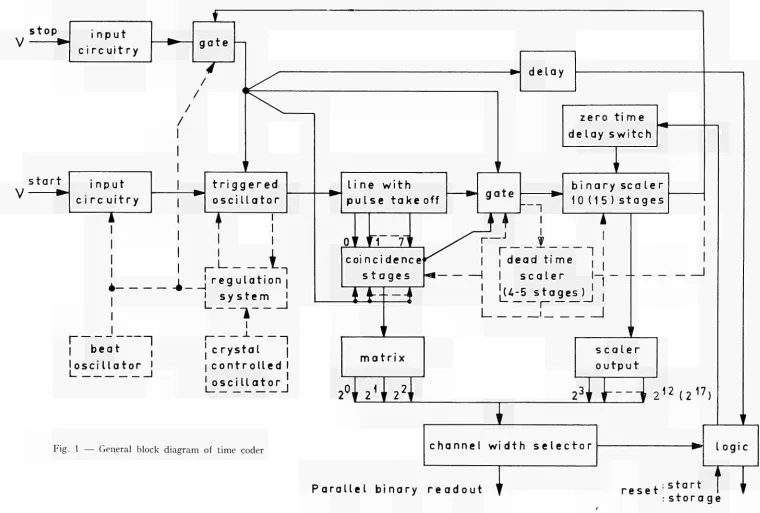
Let me first explain the general function (see Fig. 1) :
The unit will be started by a reference output of the neutron generator, as for instance a pulse from a master clock or a pulse detected from the primary particle burst or from the yflash. Such a pulse will go through an input circuitry and trigger on a cable oscillator with a frequency of 125 Mc/s, i.e. after start, this oscillator delivers pulses with a time distance of 8 m/¿ sec. The oscillator pulses run through a line to which eight coincidence stages are coupled by cable trans formers at a time distance of 1 ns, and after passing a gate, they are counted in a binary address scaler consisting of three tunnel diodes per stage. This scaler is at the start in a presetted condition and will deliver an output pulse when all stages are brought to the "zero" state. The number of pulses necessary to reach this condition is dependent on the adjustable state of the "zero time delay switches", which have delivered before "start" during the "reset" function pulses of suit able polarity to the binary stages.
The time between "start" and the first output pulse from the scaler is called "zero time trigger delay". This output pulse opens a gate at the "stop" input and allows now that particles to be analysed and converted in a suitable detector can initiate the "stop" function for analysis of their flight time. Such a stop pulse will go through an input circuitry with adjustable threshold and peak detection mode for amplitude independent time definition to the second inputs of the eight coincidence stages, to the scaler gate interrupting the flow of oscillator pulses to the scaler and also to the triggered oscillator for stopping this unit. In addition "readout" of information is started after a delay great enough to "set" the address. The coincidence width of the coinci dence stages is 1,5 τημ/sec, i.e. they are overlapped by 50 %, which assures that always one, sometimes two, but never three stages are activated. The outputs of the coincidence stages are bistable tunnel diode circuits which are connected to a diode matrix and the number of the coincidence unit activated will appear at the output of the matrix in binary coded form. If two coincidence stages are activated, the second one in time will be immediately reset by the first one. Obviously the coincidence units together with the coding matrix perform like the first 3 binaries of a 1,000 Mc/s scaler.
The state of the address scaler, determined by the number of pulses counted in this unit after opening the "stop" input, will appear through dccoupled stages at the output in binary coded form, i.e. for a ten stage binary scaler, the state of thirteen binaries determine the analysis time. By a channel width switch for the moment eight of them are selected for readout to a buffer memory or memory register.
When "readout" initiated by the "stop" function is finished, the storage device will
The channel width selector selects not only the channel width, but also the analysis time range. If no event arrives during analysis time, the last binary of interest will initiate directly the "reset" function ("address overflow") and no read-out can occur.
The blocks in Fig. 1 shown with dashed lines arc for improvement and extension of the coder. There is first the regulation system to reach a better long term frequency stability of the cable oscillator, which has at the moment a stability of IO-4 in a limited temperature range.
This will be good enough for the momentary conditions — 213 misées max. zero trigger delay
and 212 misées analysis region that means a maximum analysis range of about 12,000 channels
for the smallest channel width of one nanosecond. For the planned extension of the analysis range by a factor of 32 (i.e. 5 additional stages for the address scaler), the stability has to be improved.
The regulation system we have developed for this purpose is relatively simple. It inter-rupts the analysis function each second and compares for about four milliseconds the frequencies of the cable oscillator and a crystal stabilised unit. A regulation current proportional to the deviation from a mean value of difference frequency and held until the next regulation cycle begins, will correct and stabilize the frequency of the cable oscillator. The interruption of the analysis function will be done always when an analysis cycle is finished in order to avoid mal-function and complex circuitry. With the regulation system the accuracy can be about 10~5.
The coder described so far can. measure one event per analysis only. For a maximum analysis region of more than 100 ,usecs it becomes probable that more than one event will arrive during one analysis cycle for analysis and should be measured. This is possible by switching over the flow of oscillator pulses through the scaler gate from the address scaler to a deadtime scaler instead of closing the gate and stopping the oscillator. When the deadtime scaler delivers an output pulse, i.e. will overflow, settling of the address scaler and readout must be finished and this output pulse will correct the address scaler, reset the coincidence output stages, open again the stop gate and switch back the scaler gate. The deadtime for the analysis of one event will probably be 27 m/isecs, but surely not higher than 28 misées.
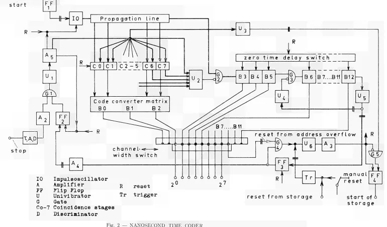
In Fig. 2 you see a more detailed block diagram of the realized coder to explain in more detail circuitry and functions responsible for the realized characteristics and the limiting factors.
The accuracy is mainly limited by the stability ot the cable oscillator (integral accuracy) and the influence of delay jitters in the circuitry (differential accuracy) (*) which were kept low by the predominant use of fast tunnel diodes. Both inputs of the coder have adjustable amplifiers and thresholds to avoid the influence of background. At the stop input, the events of whicli the arrival time is to the analysed will have a certain dynamic range of pulse amplitude; therefore a limiter and peak sensitive circuitry is foreseen to avoid the influence of excessive time jitter. As known, this jitter can be a multiple of the rise time of pulses, if their amplitudes are only by a small amount greater than a chosen threshold value.
With the realised input circuitry, the jitter from input pulse shape will be smaller ± 0.1 m/zsec for rise times smaller than 20 m/isecs and an amplitude range of ten. If the reference pulses are not fast enough or of constant amplitude, the start input will also need a peak sensitive
(*) The differential accuracy given in the text contains three main influences : first, the statistical fluctuations of channel width;
second, channel width fluctuations and shifts because of input conditions (shape and dynamic range of those pulses which determine beginning and end of a time interval to be analysed) and because of the stability of the responsible parts of the measuring equipment;
third, channel width differences because of calibration errors.
circuitry. The differential accuracy is' determined besides the input circuitry by the switching accuracy of the other elements in the start and stop path, i.e. the start flipflop (FFi) and the oscillator (IO) in the start path and the amplifiers, shapers and the stop gate (Gi) in the stop path. In addition, there is the influence of the coincidence stages. Altogether the jitter is not greater than about i 0.15 nuíscc.
For correct functioning the propagation, delay of pulses from both inputs to the first coincidence stage must normally be equal. In our case the delay in the stop input is made 64 misées longer, and this for the following reason : At the end of the zero time trigger delay, i.e. when an oscillator pulse switches all binary stages back from the "one" to the "zero" state, the binary scaler delivers an output signal for opening the "stop" gate. But because of the propa gation delay of the scaler (1.6 m«sec?/stage) and the logic circuitry on the way to the "stop" gate, some analysis pulses will be counted in the scaler before the gate can be opened. Therefore the scaler must be reset and the system has to start counting the analysis time at the moment the first possible stop pulse after opening of the stop gate can arrive at the first coincidence stage. The reset of the scaler is done by gating off the first pulse from the 3rd to the 4th binary which appears after the end of the zero time trigger delay. This means a reset of 64 misées in the scaler. As gate pulse the suitably delayed scaler output pulse is taken. Because of a possible propagation delay jitter rf the oscillator pulse on its way through the system which opens finally the "stop" gate, this gate must be opened a little later than is necessary to analyse in channel "Ì" in order to avoid a possible malfunction which could occur if the stop gate would be opened a little too early and a "stop" pulse would be there at that moment. Then the scaler would have been stopped before the 64 ιημ/sec reset was finished. The mentioned necessary precaution because of jitter influences will only introduce wrong analysis in the first one or two channels of smallest width.
Another possible malfunction — in this case an analysis error of eight channels — can occur if tinder the worst conditions a coincidence will appear in stage C7 and the scaler gate has not been closed early enough to avoid counting of the oscillator pulse belonging to this coinci dence or if a coincidence will appear in CO and the scaler gate is closed before the preceding oscil lator pulse has been counted. Such a malfunction is completely avoided by closing the scaler gate with the stop pulse only for a coincidence in CO to C3 and introducing the gate function for a coincidence in C4 to C7 by the output pulses of the coincidence stages themselves and in addition by right adjustment of delays as further explained in Fig. 3.
If during the chosen analysis time no analysis will happen, i.e. the address will "over flow", a pulse from the last address binary of interest will activate the "reset" function through gate G4, which is only possible at the end of the analysis time, because G4 has to be preset by FF3 which is activated by the pulse opening of the stop gate at the beginning of analysis. For the future system with the possibility of multiple storage per analysis cycle, the "address over flow" function will always initiate "reset".
O U T P U T CONNECTIONS
As mentioned before, storage devices are connected to the output stages of the coder through a channel width selector which selects the binary stages of interest for readout.
Storage is initiated by a "startofstorage" pulse from the coder (FF4) and its reset func tion by an "endofstorage" pulse from the storage device.
CHARACTERISTICS
In Fig. 4 you find the characteristics realised and in brackets the planned extensions mentioned earlier.
In Fig. 5 the frequency variation of the cable oscillator vs. temperature is given. It should be mentioned that because of special lay-out no duty cycle effects after the start of the oscillator will influence the accuracy of analysis.
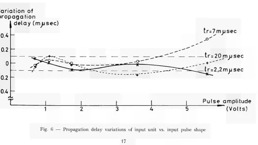
Fig. 6 shows the stability of propagation delay for the input unit with amplitude inde-pendent time definition for various input pulse conditions. An influence of ambient temperature on characteristics was not measurable between 20° C and 35° C.
More details about the cable oscillator, the address scaler, which could count pulse rates up to 300 Mc/s and the input system with amplitude independent time definition will be pu-blished in the near future.
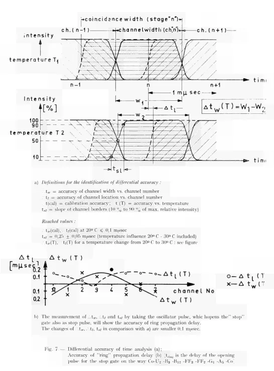
In Fig. 7 measurements are shown to demonstrate the differential accuracy and also the internal jitter influences at temperatures between 20° C and 30° C. For testing the integral accur-acy, time distances of several microseconds were measured with one nanosecond resolution using shaped pulses from a crystal controlled oscillator.
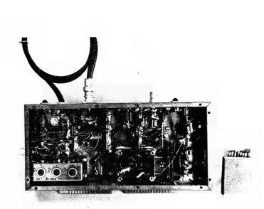
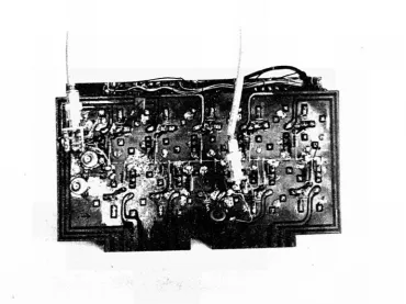
Figs. 8, 9 and 10 will give an idea of the technology used for the equipment.
POSSIBLE IMPROVEMENTS
Besides the planned extensions mentioned, i.e. increasing the maximum analysis time by a factor of 32 and the integral accuracy up to a value better than 10~5 and also the
introduc-tion of multiple storage per analysis cycle, other improvements are not planned for the moment, but remain possible.
With the results shown, there exists the possibility of reducing minimum channel width. A factor of two to four can probably be realized, if adjustments are carefully made and jitter effects are reduced, as for instance by compensating the temperature dependence of the thres-holds in the coincidence circuits. For a reduction of the minimum channel width by a factor of four, the number of coincidence stages should be increased by a factor of two and a second pulse train available from the cable oscillator occurring one half period later than the first train will be used. Then the address scaler must count a pulse rate of 250 Mc/S.
Such improved configurations are possibly practical for certain applications, as for in-stance the precise determination of an electron emission up to 2 //sees after the arrival of a // meson as mentioned by Pizer (4) (Determination, of the "Muon gyromagnetic ratio").
An improvement of integral accuracy from 10^5 for the moment in mind with the
men-tioned regulation system up to about 10~6 seems to be possible with a more elaborated
regu-lation circuitry.
R E S U M I N G R E M A R K S
In resuming the results of our developmental works and studies for fast time coders with great analysis range, one can say that in comparison with equipment realized earlier, the small-est channel width (i.e. energy resolution) for such systems was improved by a factor of ten and can be improved further by a factor of two to four.
In addition, especially advantageous for use with accelerators of high particle density per burst, the necessary time for the analysis of one event will be about 0,1 to 0,2 //sec.
In. order to fully use the advantages of the realized system for neutron time-of-flight analysis improvement of accelerators will be necessary.
L I T E R A T U R E
1 — LEFEVRE and RUSSEL — IRE Transact, on Nucl. Sc. 146, (Dec. 1958).
2 — FERGUSON, ORMAN, MONTAGNE — Conf. Belgrade, May 1961 — Nucl. Electronics,
Vol. Ill, p. 335.
3 — COTTINI, GATTI — Nuovo Cimento 4, 1550 (1956).
4 — H.I. PIZER — CERN Report 59-27, (1959).
s t o p
s t a r t i n p u t
c ¡ r e u i t r y
ι—
ι
4
t r i g g e r e d o s c i II a t o r
Τ
ι
L
. , - Λ
ι ! r e g u l a t i o n |ι s y s t e m ι
Γ
b e a t
Ί
l o s c i l l a t o r ι
I I I
c r y s t a l Ί I c o n t r o l l e d I
I
[image:17.842.39.799.32.545.2]' o s c i 11 a t o r j
Fig. 1 — General block diagram of time coder
z e r o t i me de lay s w i t c h
υ
l i n e w i t h
p u l s e t a k e off ^ g a t e
Ί
I
c o i n c i d e n c e s t a g e s
TYF1
I | d e a d t i me —I I s c a l e r
I I
bi n a r y sea 1er 1 0 ( 1 5 ) s t a g e s
ι
Ί I
! - '
ι
1ι
¿*i
5_
si.
al«Lj ι
ι
L.
I
m a t r i x
' J 2
<
J 2
2
|
s c a l e r o u t p u t
I
£Θ
21 2( 21 7}
c h a n n e l w i d t h s e l e c t o r
Pa r a l l e l b i n a r y r e a d o u t γ r e s e t : Sta r t T f
s t a r t
1 1
F F
1
R — S '
IO
Τ
P r o p a g a t i o n U n e
U
' G ì
0
\ \
L.A.U
A 2
s t o p
F F 2
i
t
w w1
C o d e c o n v e r t e r m a t r i x BO B 1 Β 2
« «c— R
c h a n n e l - ·«?—a»» w i d t h s w i t c h
* >—< ►—t >—< >—<►—<>—<»—ι > — »
Hh-IO
Impuleoecillator
A
Amplifier
R r e a e tFF
Flip Flop
U
Univibrator
Tr trigger
G
Gata
Co7 C o i n c i d e n c e e t a g e e
D
D i β c r i m i n a t o r
z e r o t i m e d e l a y s w i t c h
I
I
B 6
Τ
Β 7....Β 11 B12
B 7 Β 11
U
G ) _ ^ψ
Ó Ó Ô Ô Ô Ó Ô Ô
F F 3
U
r e s e t f r o m a d d r e s s o v e r f l o w
η
Hh»
ITL
1
T r t — * - m a n u a l r e s e t
ψ7
iL
F F 4 r e s e t f r o m s t o r a g e o s t a r t of o
s t o r a g e
Fig. 2 — NANOSECOND TIME CODER
[image:18.842.35.805.82.535.2]Last pulse to
be counted
O s c i l l a t o r p u l s e s at
t he s c a l e r g a t e :
_TL
Pulse which is in coincidence
with the stop pulse
_i_
Closure of the scatergate / Co
in relation to the arrival
time of oscillator pulses
at the gate for
coincidence in :
t 1 M 1 | t r |
-1 2 3 A 5 6 7 8
[image:19.842.125.738.122.418.2]time scale(m>irec)
Fig. 4 — CHARACTERISTICS OF NANOSECOND TIME CODER
Analysis time : 1.5 · 21 3 m//sec = 12.288 ¿¿sec max. [x32].
Zero time trigger delay : 213 m^sec = 8.192 /¿sec max. [x32] adjustable in steps of 8 m^sec;
8 m,asec. min.
Analysis range
Channel width
Accuracy
4.096/channci width channels [ x 3 2 ] .
1, 2, 4, 8, 16 m^sec.
better (10~4 χ Analysis time) + 0.5 nn/sec in the temperature range
20" C 30° C.
[ΙΟ""5 χ Analysis time + 0.5 m/zsec].
Number of events, which can be stored per analysis cycle : one,
[More than one; minimum necessary time for the storage of one event < 0.2 //sec it a prebufler storage is used].
Af(Kc/s)
125 Mc/s
[image:21.595.43.552.58.771.2]_50
Fig. 5 — Frequency of the unregulated cable oscillator vs. temperature
Variation of
propagation
delay (musec)
0.4
0.2
0
-0.2
-0.4
tr=7nnij sec
- t r r 2 0 m j j s e c
- + -"""
tr=2
;2musec
[image:21.595.31.557.455.750.2]Pulse amplitude
(Volts)
Fig. 6 — Propagation delay variations of input unit vs. input pulse shape
»coincidance w i dth ( stage'n")»
i n t e n s i t y
t e m p e r a t u r e T^
-ch. (n + 1
)-I n t e n s i t y
te s p e r a t u r e Τ 2
a) Definitions for the identification of differential accuracy :
t„. = accuracy of channel width vs. channel n u m b e r . ' t / = accuracy of channel location vs. channel n u m b e r
t(cal) = calibration accuracy; t (T) = accuracy vs. t e m p e r a t u r e ts; = slope of channel borders (10 % to 90 % of max. relative intensity)
Reached values :
/.t„,(cal), .,.t,(cal) at 20° C < 0,1 m«sec
ts i = 0,25 + 0,05 m/isec (temperature influence 20° C 30° C included) t„(T), . t/(T) for a t e m p e r a t u r e change from 20° C to 30° C : see figure
A t
["^"Siê
Δ t
w
(T )
w
0
0.2 +
- o - . A t
L( T )
c h a n n e l No
A t
w( T )
O— Δ t
L( T
Χ — Δ t
w( T
b) The measurement of .ò.tw, ¿.t/ and ts¡ by taking the oscillator pulse, whic hopens t h e " s t o p "
gate also as stop pulse, will show the accuracy of ring propagation delay. The changes of .',t,„, ,\t¡, ts/ in comparison with a) are smaller 0.1 m//sec.
Fig. 7 — Differential accuracy of time analysis (a);
[image:22.595.29.576.37.778.2]Fig. 8 — Time coder, first version (provisional)
■uilCU
Fig. 9 — Cable oscillator with start and stop gates
[image:23.595.100.461.62.344.2] [image:23.595.92.464.404.698.2]Fig. 10 — 10-bit binary address scaler with tunneldiodes
wmm
^lAwfeKttt^røwrauM «Efe
{•rm
thü(l
«■niPHNBBi f f f
«AT '
mm
EJE
o l i l i nlt"IS!«<w
*-le
ΐίΗϊΛΐΙΪΜ*
![Fig. 3 — Time conditions at the scaler gate for the stop function Gate closure by a pulse from the stop input (sto) and/or a pulse from a coincidence unit (("„)]](https://thumb-us.123doks.com/thumbv2/123dok_us/7933756.749684/19.842.125.738.122.418/time-conditions-scaler-function-gate-closure-input-coincidence.webp)