SPEED CONTROL OF SINUSOIDALLY EXCITED
SWITCHED RELUCTANCE MOTOR USING FUZZY LOGIC
CONTROL
1P.KAVITHA,, 2
B.UMAMAHESWARI 1,2
Department of Electrical and Electronics Engineering, Anna University, Chennai, India 2
Department of Electronics and Instrumentation Engineering, RMK engineering college, Chennai, India
E-mail: [email protected]
m
, 2umamahesb@annauniv
.
eduABSTRACT
This paper presents the speed control of SRM which is directly fed from an AC supply through a simple R dump converter. The controller uses fuzzy logic control (FLC) for switched reluctance motor (SRM) speed. The FLC performs a PI-like control strategy, giving the current reference variation based on speed error and its change. The performance of the drive system was evaluated through digital simulations through the toolbox Simulink of Matlab program. Merits and demerits of the proposed control algorithm are brought out.
Keywords: Switched Reluctance Motor, R Dump Converter, Sinusoidal Excitation, Speed Control, Fuzzy Logic Control.
1. INTRODUCTION
SRM is a simple motor in construction and in operation. It produces a torque of reluctance type, which is independent on the polarity of the current through winding. It has many advantages like efficiency, cost, no maintenance, higher torque volume ratio etc. it has certain disadvantages like non linear magnetic characteristics, acoustic noise and high torque ripple. A huge research works on this machine has been reported in [1]-[2].
Analog control is the best suitable control mechanism for any industrial drive. The conventional PID controller is highly robust and can tackle any disturbance in a system but it requires proper tuning. Different non linear control techniques like sliding mode, fuzzy logic control, and artificial neural network control are common. These controls have shown a good prospect to bring robustness and adaptive nature in constant speed variable torque or constant torque variable speed drive application. Fuzzy logic (FL) based speed controller is used successfully instead of the conventional PID speed controller. FL can be applied in the form PI controller, called as PI like FLC, where the PI controller parameters are automatically tuned for a wide range of speed demand and also for a wide change in operating condition. Literature studies on switched reluctance motors and these controllers are as follows: Torque
ripple in SRM has been overcome by implementing an adaptive control of the system. The output of the controller is demand current, which is a weighted value using LMS algorithm [3]. Reference [4]-[5] discuss the sliding mode control (SMC) based on fuzzy logic is incorporated which explores the performance as a simulation work.
In reference [14] simulation and analysis, have derived and demonstrated that a minimal neural network configuration is attainable to implement rotor position estimation in SRM drives. Reference [15] explains about the use of a hybrid controller consisting of PI and FLPI controllers and they have compared the performance of this controller with those of PI, FLPI and FLPD controller, in respect of steady state error.
In this work the objective is achieving SRM speed control in MATLAB/Simulink by self tuning fuzzy PI controller. For this purpose, the dynamic model of 8/6 1.5 hp SRM is obtained using Fourier method. Using this model performance of the controller is compared with the performances PI controller.
2. SRM DYNAMIC MODELLING
In this section we focus on the electro mechanics of switched reluctance machines (SRM). The intent is to provide an understanding of energy conversion process. Switched reluctance machines can work as motor or as generator just by changing their switching angles and control the path of energy generated. Regarding the operation of the machine, when rotor pole is in line with the energized stator pole, the position is said to be a stable equilibrium. When the rotor pole is not aligned with an energized stator pole is said to be an unstable equilibrium. Rotor will tend to turn to the position of balance featuring a motoring operation. Thus in SRM there is a natural tendency to align the rotor and the stator active poles in order to maximize the inductance of that phase.
A per phase equivalent circuit of SRM can be derived as below. The mutual inductance between the phases is neglected. The voltage applied to each phase is equal to the sum of resistive voltage drop and the rate of change of flux linkages in the corresponding phase and is given by eqn (1)
Vk=Rkik+ dλk/dt (1) where k is the number of SRM phases, Vk is the applied voltage, ik is the phase current, Rk is the resistance of the phase winding. Lk is the inductance of phase winding which depends on position and current.
λk is the flux linkage which is given by,
λk=Lk(θ,ik)ik (2)
Substituting equation (2) in equation (1) and derivate it we get,
Vk=Rkik+ Lk(θ,ik)dik/dt+ikω∂Lk/∂θ (3)
where ω is the speed of the motor in rad/sec which is given by
ω=dθ/dt (4)
The instantaneous torque developed Td by the motor is the sum of the phase torques which is given by the equation,
Td =
∑
=
n
i1
0.5ik2∂Lk/∂θ (5)
The mechanical equation of the motor is given by
Td-TL=Jdω/dt+Bω (6)
[image:2.595.320.475.320.419.2]TL is the load torque, J is the moment of inertia, B is the friction coefficient of the motor. Considering equations (1) – (6) the mathematical model for the SRM is made which explains the complete dynamic behavior of the machine.
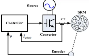
Figure 1: Block diagram of direct AC fed SRM
Figure 1 shows the block diagram of the direct AC fed SRM. The SR drive consists of a motor, position sensor, converter and controller. The current sensor and the position sensor provide the information about the phase currents and rotor position to the controller in order to excite the suitable phase of the machine. The controller also regulates the SRM performance. The hysteresis current controller is easy and simple controller for the SRM control. Due to its inherent nonlinear capabilities artificial techniques are preferred.
3. CONVERTER TOTPOLOGY
and applied to the converter. The converter is now compact and less weight.
Figure 2: Rdump converter with sinusoidal excitation
The converter has two modes of operation. During excitation mode the controlled switch T1 is turned on based on the information from the position encoder. During this period the phase winding is excited from the supply for a fixed dwell angle. After the turn off angle the switch is turned off and the diode is forward biased. The energy stored in the winding is dissipated in the resistor R. This period is called as the regeneration period of SRM
.
4. SPEED CONTROL OF SRM
In figure 3, the block diagram of the speed control of SRM is seen. The output of the speed controller is, the reference current i*. In this paper, the fuzzy logic controller tuning is used as the speed controller. The system also consists of a hysteresis band controller which does current control, a converter and a trigger circuit which drives the switches in the converter into conduction or cut off.
4.1 Conventional PI Controller
Conventionally PI controllers are widely used in industrial application, due to their simplicity, low cost and robustness. These controllers can also be implemented easily through analog components. The general operation of PI controller can be represented by following
Ms(t)=KPe(t)+KDde(t)/dt+KI∫e(t)dt (7) where
e(t)=ω*- ω
r (8)
Where, e(t) is the speed error, Ms(t) is the output of the controller ,KP is the proportional constant, and KI is the integral constant with KD = 0. Thus the controller provides an appropriate feedback. The reference speed ω* is compared with the actual speed ωr to get the speed error e(t) as shown in figure 3. Depending on the position and current
controller information the converter gets the triggering pulses.
4.2 Fuzzy Logic controller
[image:3.595.300.500.313.401.2]FLC can be employed to evaluate output variables when an exact mathematical relation with the input variables cannot be formulated. It differs from the conventional system in several aspects. The main feature of FLC is that it is governed by symbolic rules (generally if-then rules) and qualitative fuzzy variables and values. It deals with linguistic variables. Fuzzy logic approximates the relation between variables regardless of their analytical dependence. The inputs of FLC are e(t) and de(t). The block diagram for the fuzzy based PI controller is shown in figure 4.
Figure 4: Block diagram of fuzzy based PI controller
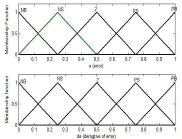
In this paper, the triangular membership function is used for the variables and its derivative, trapezoidal membership is used for the output variables, the max-min reasoning method, and the centre of gravity defuzzification method are used, as those methods are most frequently used in many literature. If-then rule is used to form the rule based fuzzy logic. Here NB is negative big, NS is negative small, Z is zero, PS is positive small and PB is positive big are the labels of fuzzy set and their corresponding membership functions are depicted in figure 5.
[image:3.595.308.490.558.697.2]Figure 6: Trapezoidal membership functions for the output variables KP and KI
The trapezoidal membership function is chosen for the output variables Kp and KI is given by variables NB is negative big, NS is negative small, Z is zero, PS is positive small and PB is positive big which is shown in figure 6. The rule base for the fuzzy set is shown on Table 1. Using on this with IF-THEN twenty five rules can be formed for the tuning of the controller.
TABLE 1:RULE BASE FOR GLOBAL FUZZY SET
e
de
NB
NS
Z
PS
NB
NB
Z
PS
PB
PB
PB
NS
NS
Z
PS
PB
PB
Z
NB
NS
Z
PS
PB
PS
NB
NB
NS
Z
PS
PB
NB
NB
NB
NS
Z
5. SIMULATION RESULTS ANALYSIS
[image:4.595.92.282.346.473.2]In order to validate the control strategies as discussed above digital simulation studies were made. The simulation is realized using the Simulink software in Matlab environment. To see the entire output surface of system the surface viewer is generated which is given in figure 7.
Figure 7: Surface viewer for output variables KP and KI
The drive responses to a speed reference step with the motor unloaded is first presented. Using a PI controller, a good compromise for Kp and KI parameters has been found in order to have
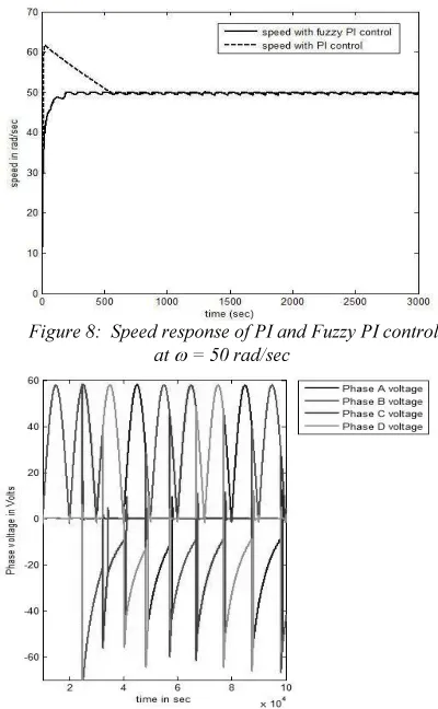
less speed oscillations. The simulation of the starting mode without load is done. A simulation test was achieved for three speed reference signals, respectively: 50, 100 and 500 rad/s. The speed response for the conventional PI and fuzzy PI are shown in figure 8. The conventional PI shows peak overshoot when compared with the fuzzy speed control. The settling time is also large and it has large ripples. The phase voltages and phase currents of the SRM are given in figure 9 and figure 10. The simulation is run with turn on angle θon= 45° and
θoff =75°. The negative voltage is the back emf feedback during the regeneration period. In the Rdump converter the regenerative power is dissipated as heat. But various methods are found in literature stating flywheel storage etc to have more efficiency of this drive.
[image:4.595.305.505.401.725.2]The developed torque of this SRM is given in figure 11. The torque at the time of starting gives a large value similar to the series motor. The torque has more ripples due to the high switching rate of the converter. Various torque ripple minimization techniques are given in literature can be used to reduce the ripples present in torque.
Figure 8: Speed response of PI and Fuzzy PI control at ω = 50 rad/sec
Figure 9: Phase voltage of SRM with Fuzzy PI control at
[image:4.595.87.291.580.679.2]Figure 10: Phase current of SRM with Fuzzy PI control at ω = 50 rad/sec
Figure 11: Developed Torque response of Fuzzy PI control at ω = 50 rad/sec
[image:5.595.88.508.74.466.2]Further to analyse the performance of the fuzzy converter the simulation is run under various speed conditions. Figure 12 shows the speed response of PI and fuzzy PI controller when ω=100rad/sec. The fuzzy controller shows a better response compared with the conventional PI controller. Figure 13 is showing the speed response for 500 rad/sec. From the graph we found sluggish response intially and more steady state error in fuzzy control.
Figure 12: Speed response of PI and Fuzzy PI control at
ω = 100 rad/sec
Figure 13: Speed response of PI and Fuzzy PI control at
ω = 500 rad/sec
Figure 14: Phase inductance profile of SRM
[image:5.595.309.505.552.719.2]Figure 14 shows the inductance profile of the proposed SRM. The minimum or unaligned inductance is 10mH and the aligned inductance is 60mH. The inductance profile is cosine in nature. Hence Fourier method of modeling is possible for the analysis.
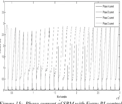
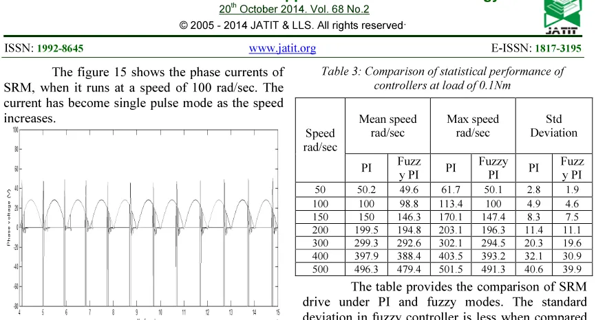
[image:5.595.94.286.580.713.2]The figure 15 shows the phase currents of SRM, when it runs at a speed of 100 rad/sec. The current has become single pulse mode as the speed increases.
Figure 16: Phase voltage of SRM with Fuzzy PI control at ω = 100 rad/sec
The phase voltage of SRM whent it runs at 100 rad/sec is shown in figure 16. The supply is sinusoidal. When the phase is in regenerative mode it returns the induced emf
The comparison of statistical performance of the speed control is listed in table 2. The mean value maximum value and standard deviation are listed. The fuzzy control shows a better performance than the conventional PI controller. At higher speed the deviation is found to be more in the proposed controller. Table 3 is listed with the statistical analysis data with load torque of 0.1Nm. In this loaded condition also the proposed controller shows a better performance. In both the conditions the fuzzy controller performs in a efficient manner and almost the peak over shoot is eliminated.
Table 2: Comparison of statistical performance of controllers at no load
Speed rad/sec Mean speed rad/sec Max speed rad/sec Std Deviation
PI Fuzz
y PI PI Fuzz
y PI PI Fuzz y PI
50 50.2 49.6 61.7 50.1 2.8 1.9
100 100 98.8 113.4 100 4.9 4.6
150 150 146.3 170.1 147.4 8.3 7.5
200 199.5 194.8 203.1 196.3 11.4 11.1
300 299 292 302 294.5 20.3 19.6
400 397.9 388.4 403.5 393.2 32.1 30.9
[image:6.595.85.518.80.313.2]500 496.8 484.7 501.3 495.9 44.5 41.8
Table 3: Comparison of statistical performance of controllers at load of 0.1Nm
Speed rad/sec Mean speed rad/sec Max speed rad/sec Std Deviation
PI Fuzz
y PI PI
Fuzzy
PI PI
Fuzz y PI
50 50.2 49.6 61.7 50.1 2.8 1.9
100 100 98.8 113.4 100 4.9 4.6
150 150 146.3 170.1 147.4 8.3 7.5
200 199.5 194.8 203.1 196.3 11.4 11.1
300 299.3 292.6 302.1 294.5 20.3 19.6
400 397.9 388.4 403.5 393.2 32.1 30.9
500 496.3 479.4 501.5 491.3 40.6 39.9
The table provides the comparison of SRM drive under PI and fuzzy modes. The standard deviation in fuzzy controller is less when compared with the conventional PI technique. But at higher speed the fuzzy controller took much time to reach the set point.
6. CONCLUSION
A fuzzy PI controller is designed for regulating the speed of the SRM drives. The effectiveness and robustness of the proposed controller are investigated by numerical simulation. The simulation results indicate that the proposed controller is most suitable for variation in parameters. The statistical performance of the fuzzy controller is compared with conventional PI controller. The robustness verification shows that the proposed controller can handle with external load torque disturbance more effectively. It performs better in tracking capability and load disturbance rejection capability. The simulation results demonstrate that the proposed controller is effective and adequate to apply in a practical SRM drive.
REFRENCES:
[1] Krishnan R Switched Reluctance Motor Drives: modelling, simulation, analysis, design and applications; CRC Press, 2001
[2] Miller T.J.E Switched Reluctance Motors and Their Control, Magna Publishers, 1993 [3] Sayeed Mir, Malik E. Elbuluk and Iqbal
Hussain; “Torque Ripple Minimization in Switched Reluctance Motors Using Adaptive Fuzzy Control”; IEEE Transactions on Industrial Applications; Vol.35, No. 2 March/April 9 pp 461-466.
Industrial Applications; Vol 32. No. 5, Sept /Oct’1996 pp1063-1067
[5] Bhim Singh, VK Sharma and SS Murthy 1998 “Performance Analysis of Adaptive Fuzzy Logic Controller for SRM Drive System”;
IEEE PEDS ’98 Conference proceedings; pp 571-579
[6] Ho W K, Panda S K, Lim K W, Huang F S Gain-scheduling control of the switched reluctance motor. Control Eng. Practice 6: 181–189, 1998
[7] Chen H, Zhang D, Cong Z-Y, Zhang Z-F 2002 Fuzzy logic control for switched reluctance motor drive. Proc. of the 1st Int. Confer. on Machine Learning and Cybernetic, Beijing, 145–149
[8] Rodrigues M G, Suemitsu W I, Branco P, Dente J A, Rolim L G B 1997 Fuzzy logic control of a switched reluctance motor. IEEE Int. Symp. on Ind. Electronics (ISIE’97), Portugal, 527–531
[9] Husain I, Hossain S A 2005 Modelling, simulation, and control of switched reluctance motor drives. IEEE Trans. on Ind. Electronics
52: 1625–1634
[10] Kjaer P C, Gribble J J, Miller T J E 1997 High-grade control of switched reluctance machines. IEEE Trans. on Industry Appl. 33: 1585–1593
[11] Cheok A D,Wang Z 2005 Fuzzy logic rotor position estimation based switched reluctance motor DSP drive with accuracy enhancement.
IEEE Trans. on Power Electronics 20: 908– 921
[12] Kioskeridis I, Mademlis C 2005 Maximum efficiency in single-pulse controlled switched reluctance motor drives. IEEE Trans. on Energy Conversion 20: 809–817
[13] Xia C, Chen Z, Xue M 2006 Adaptive PWM speed control for switched reluctance motors based on RBF neural network. IEEE Proc. of the 6th World Congress on Intelligent Control and Automation, China 8103–8107
[14] Hudson C, LoboNS, Krishnan R 2004 Sensorless control of single switched based switched reluctance motor drive using neural network. The 30th Annual Conference of the IEEE Industrial Electronics Society, Korea, 2349–2354
[15] Paramasiwam S, Arumugam R 2005 Hybrid fuzzy controller for speed control of switched reluctance motor drives. Energy Conversion and Manag. 46: 1365–1378
.