Technology (IJRASET)
+
Optimized Interaction of PODC and SSSC To
Improve the Transient Stability Performance In
Power System
G.Muthuselvi1, M.Sudhakaran2, A.Bharathi3, M.Shanmugasundaram4 #
Departement of EEE, Ganadipathy Tulsi’s Jain Engineering Collège, Kaniambadi, Tamilnadu, India
#
School of Electronics Engineering, VIT University, Vellore, Tamilnadu, India
Abstract— The enlargement of the contemporary power system has lead to an increasing difficulty in the study of power systems, also presents new challenges to power system stability and in meticulous to the aspects of transient stability. This paper presents the algorithm for interfacing Voltage Sourced Inverter with Static Synchronous Source Series Compensator (SSSC).The modelling of the controller plays a major role in the performance of the SSSC. The performance of SSSC for different mode of operation using PI controller and sliding mode controller is being studied. The Power Oscillation Damping Circuit (PODC) is used to damp out power oscillation. The simulation was performed on a 9-bus power system modelled for stability studies. The results clearly indicate that introduction of SSSC devices in an appropriate location increases the power flow of the system and improves transient stability, by controlling its mode of operation by developing sliding mode controller module. The simulations and analysis were carried out using the MATLAB Software Package.
Keywords— SSSC, PODC, MATLAB, Sliding Mode System.
I. INTRODUCTION
In recent years, a number of Flexible AC Transmission System (FACTS) controllers, based on the increased development of power electronics technology, have been proposed. .It is well known that series compensation can be used to increase the maximum transfer capabilities of power networks with the use of FACTS. Claudio A. Canizares [3], presented transient stability and power flow models of FACTS controllers for voltage and angle stability studies of power system. The SSSC is a series connected synchronous voltage source that can vary the effective impedance of a transmission line by injecting a voltage containing an appropriate phase angle in relation to the line current. [9] [10]. B.N.Singh [12], examined the dynamic performance of sliding-mode and fuzzy controllers for a static synchronous series compensator. This paper examines transient stability improvement with SSSC by tuning controller parameters using EP. PI controllers are linear controllers which are effective for the operating condition for which it is designed. It is more sensitive to parameter changes. Therefore there is a need for a robust controller which is insensitive to parameter changes. Hence in this paper, non-linear control based on variable structure technique is developed.
II. MODELLING OF POWER SYSTEM COMPONENTS
A. Synchronous Machine Model
The synchronous generators are modelled as classical machines with rotor angle and speed as state variables.
(1)
(2) 0
d
J Tm Te dt d dt
B. Transmission Line Model
Technology (IJRASET)
C. Load ModelThe loads are modeled as a constant admittance in transient stability studies.
D. SSSC
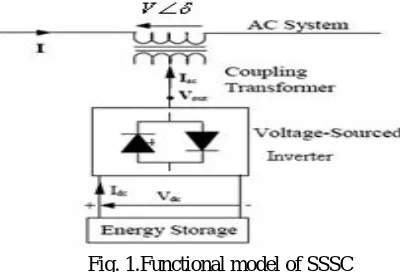
[image:3.612.205.405.194.330.2]1) Principle Of Operation: The line side transformer winding is connected in series, placing the VSI also effectively in series with a transmission line, and thus allowing series compensation of the line The SSSC is typically restricted to only reactive power exchange with the nearby ac system, neglecting the small amount of real power used to cover the circuit and switching losses, because of the relatively small SSSC capacitor. If the dc capacitor were replaced with an energy storage system, the controller would be able to exchange real power with the ac system and compensate for the transmission line resistance [4] [5].
Fig. 1.Functional model of SSSC
[image:3.612.200.410.383.522.2]2) Transient Stability Model: Assuming balanced, fundamental frequency voltages, SSSC with PWM voltage control can be accurately represented in transient stability studies using the basic model shown in Fig. 2
Fig 2. Transient stability model of SSSC
3) Transmission Line Current Controller: This controls the magnitude of series injected voltage of SSSC by controlling the modulation index mse of the PWM controller. The controller has a bias corresponding to the steady state value of the modulation
index mse0
Technology (IJRASET)
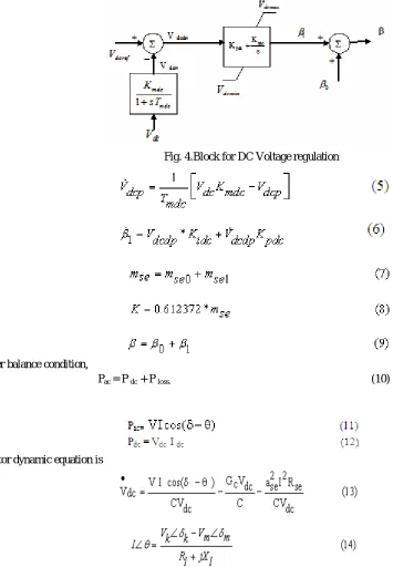
[image:4.612.86.441.191.703.2]4) DC Voltage controller: This controls the phase angle of series injected voltage by varying . It is used to directly control the DC voltage magnitude. The controller has a bias corresponding to thephase angle 0
Fig. 4.Block for DC Voltage regulation
From power balance condition,
Pac = P dc + P loss. (10)
From Fig 2
Technology (IJRASET)
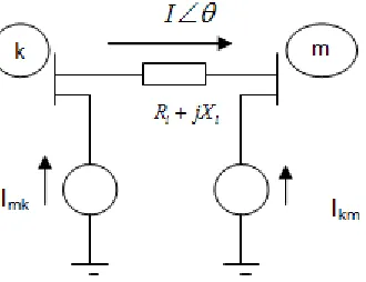
[image:5.612.237.402.133.260.2]5) Representation Of Synchronous Machine And SSSC: The generator is represented by the Norton equivalent for network solution [6]. The admittance of the generator is included in the main diagonals of Y matrix.The SSSC is interfaced with network by current injection model since it suits with transient stability algorithm.
Fig 5. SSSC current injection model
From the Fig. 5, the current injected by SSSC to the HVAC bus is
E. Modelling Of Power Oscillation Damping Controller
Fig. 6 PODC Model
The Power Oscillation Damping Circuit is used to damp out power oscillations. The main objective of this circuit is to filter out undesirable signals and provide a phase lead to the signal to compensate for phase lag. The washout circuit is to eliminate steady state bias in the output of the ac system. The input signal may be a current, speed or power [9][12].
1 1
2 1* 1 1 2 2 (17) (18)
1
(
*
*
)
1
(
)
c w s
w
x
K
T
x
x
T
x
T x
x
x
T
F. Design Of Sliding Mode Controller
The SMC includes an equivalent control term and a switching term. The design of the SMC includes the selection of sliding surface and the control law. The control law must satisfy the reaching condition and guarantees the existence of the sliding-mode. The SMC is applied to control the DC voltage of the capacitor.Define the state variable as follows:
Technology (IJRASET)
Where, Vdc ref is the capacitor DC voltage reference1) Selection Of Sliding Mode Controller: The conventional SMC employs the acceleration signal, which is sensitive to the noises. To overcome this problem an integral sliding surface is used in the investigations. The sliding surface is chosen as follows:
Where c is a positive constant and is chosen for the desired system dynamics. Since‘s’ is zero from the beginning, complete robustness is achieved in the whole transient and the system will converge asymptotically to the origin with time constant of 1/c.
2) Design of Equivalent Control Term: The control law should be selected to guarantee the states move along the sliding surface, realizing the robust control. The equivalent control term keeps the system with nominal parameters on this sliding surface.
From Eq. (20) and Eq.(21), and let
0
s
, Eq. (22) is derived:Where
3) Design Of Switching Term:A boundary layer is introduced neighboring to the sliding surface to eliminate chattering. Then the control is written as:
Where, is the thickness of the boundary layer and the saturation function is
The introduction of boundary layer results in a steady-state error. To reduce chattering and steady-state error as well as to achieve fast response, saturation term is modified to yield the switching term as,
The switching term always has same sign with , but the control effect is different. Since the switching term changes continuously, fast dynamic response is achieved and the chattering phenomenon is eliminated
Technology (IJRASET)
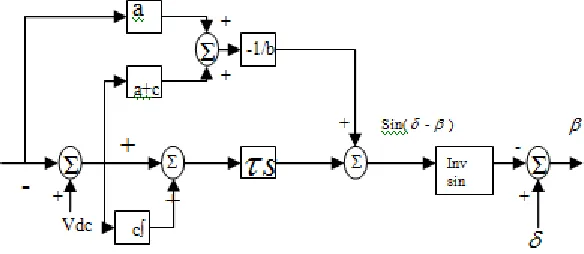
4) Structure Of Sliding Mode Controller:Fig. 7 Structure of Sliding Mode Controller
G. Tuning Of Controller Parameters Using EP
The objective function is to minimize the sum square deviation of rotor angle oscillations satisfying the constraints. The tuned values of controller parameters from EP for each time step is used in transient stability program.
Objective function:
subject to
III. TRANSIENT STABILITY ALGORITHM
The stepwise computations to be performed to advance the simulation by one step from t-
t
to t are as follows. The time step width (
t
) used in the algorithm is 0.01 sec.A. Assumptions
Classical machine model is considered (no controllers) Dampings are ignored
Loads are assumed as constant admittances
B. Preparation
The initial conditions for
,
and voltages are obtained from load flow and the past history terms for
and
are obtained from the initial conditions.The initial past history terms for SM, SSSC, PODC and SMC are calculated assuming the system in steady state initially.
1) Predict
Using Dahl’s Formula:
2 t
(t) 2 (t t) (t 2 t) Pm P(t)
pred
Technology (IJRASET)
2) Forming RHS Of Algebraic Equations:Rotate Norton sources by change in
(initially
pred(t)
(t
t)
; later
corr
(previous iteration) Find the Norton current injections at all the generator buses and STATCOM connected bus.For synchronous machine :
1 '
nor
Eq I
R jXd
For SSSC connected line :
V Ikm
Rl jXl
V Imk
Rl jXl
3) Solve The Network Equations [Y] Tranbus [V] = [I] Nor To Get The Approximate Value Of Synchronous Machine Terminal Voltage Vapprox
4) Compute Stator Currents Ii InoriYnori*Vi And Also Real Power Outputs Of All Generators. Pgeni Re{V Ii i*}
5) Correct
Using Trapezoidal Discretized Mechanical System Equation.2 t corr
(t) 0T (t)e H(t t)
8H
Where
H(t t) (t t) t 0
(t t) 1
t2 0
2Tm T (te t)
8H
6) Check For
Convergence. If Yes Move To Next Step; Else
corr=
pred And Go To Step 2.I7) Compute Generator Internal Variables And Update Past History Terms For SM , SSSC, PODC and SMC 8) Advance Time And Go To Step 1
C. Handling Network Discontinuities
Consider at t=td network discontinuity occurs; this causes jump in voltage, current and power.
After convergence at t=td- we obtain a network solution which is a normal time advance solution. This is referred to as the first solution at the discontinuity.
Change Y to reflect the effect of network switching and refactorize.
Perform another network solution with the refactorized Y. This is referred to as the second solution.
Note
The loads are converted in to the constant admittances and these are pushed in to diagonal elements of the corresponding load buses. Y TRANBUSii = Y ii+ Y Li Here i is for all load buses
The diagonal elements of Y bus corresponding to all synchronous generators are modified as:
Y TRANBUSii = Y ii+ 1/ (R 1i+ j X d’)
IV. SYSTEM STUDY AND SIMULATION RESULTS
A. SSSC
Technology (IJRASET)
Fig. 8. Single line diagram of 9-bus system with SSSC connected between buses 7 and 5
1) Without PODC:
0 5 10 15 20 25 30 35
0 2 4 6 8 10 12
time in secs
re la ti v e r o to r a n g le d e l 2 1 i n d e g
2) SMC Based SSSC:
Technology (IJRASET)
simulation results are presented belowV. CONCLUSION
In this paper, a standard three-machine nine bus system with SSSC has been established. From the results, it is inferred that the damping of the system is improved by SSSC PODC. Comparison of rotor angle oscillations between SMC and PI controller are depicted by considering the three input signals for PODC. It is observed that SMC is more effective in damping out the power system oscillations when omega is used as input to PODC compared to when current and power are utilized.
REFERENCES
[1] Foud.A.A, Anderson P.M (1977),”Power System Control and stability”, The Iowa State University Press, Ames, Iowa. [2] T.V Cutsem, C. Vournas (1998) Voltage Stability of Electric Power Systems, Kluwer Academic Publishers.
[3] Claudio A. Canizares, (2000) “Power Flow and transient Stability Models of FACT controllers for Voltage and Angle Stability Studies”, IEEE Power System Conference, pp. 1447-1454.
[4] Narain G.Hingorani, Laszlo Gyugi (2001), “Understanding FACTS concepts and technology of Flexible AC Transmission Systems”, Piscataway:IEEE Press. [5] R.Mohan Mathur, Rajiv K.Varma (2002),”Thyristor – Based FACTS Controllers for Electrical Transmission systems”,USA, IEEE Press.
Technology (IJRASET)
[9] Gyugyi, L., Schauder, C.D. and Sen, K.K., (1997) “Static Synchronous Series Compensator: a solid state approach to the series compensation of transmission lines”, IEEE Trans. on Power Delivery, No. 1.
[10] Sen, K.K. (1998) “SSSC - Static Synchronous Series Compensator: theory, modelling and applications”,IEEE Trans.on Power Delivery, No.1, pp241-246. [11] P. Kumkratug and M. H. Haque, (2003), “Improvement of Stability Region and Damping of a Power System by Using SSSC”, IEEE.
[12] B.N.Singh, A.Chandra, K.Al-Haddad and B.Singh (1999) “Performance of sliding-mode and fuzzy controllers for a static synchronous series compensator”, IEE Proc-Genr. Transin. Di.strih.. Vol. 146. No. 2, March 1999.
[13] Sreevidya T.R, Dawnee S,2012 - International Conference on Emerging Trends in Science, Engineering and Technology “Optimal Interaction of PSS and SSSC in a Power System Network”,IEEE
[14] Md. Shafiullah1, Md. Shafiul Alam, Md. Ismail Hossain, Md Nazmul Hasan (Dec-2014)“Transient Performance Improvement of Power System by Optimal Design of SVC Controller Employing Genetic Algorithm”,IEEE