5
X
October 2017
Wireless implicated H-Shaped Slotted Circular
Patch Antenna
Poonam Sharma1,Kapil Arora2
1
M.Tech Scholar, ECE Department, R.P.I.I.T (Bastara), Karnal 2
Assistant Professor, ECE Department, R.P.I.I.T (Bastara), Karnal
Abstract: In this dissertation, Micro strip antennas with their advantages and with the availability of tools to design were remains as a centre of research attraction. The main research aspect of the Micro strip Patch is to enhance its bands and bandwidth. To enhance the bands or bandwidth of the Micro strip Patch antenna several techniques were proposed. The slot on the patch, which increases the fringing fields, remains simple and effective technique. This paper provides an insight in the design of Micro strip antenna and presents a design of fifer band H shaped slot Circular Patch Antenna. The design utilizes the circular patch of radius 20mm and obtains multiband at the frequencies 2.44 GHz, 3.84GHz, 5.22 GHz, 6.35 GHz, 8.07 GHz. HFSS the Finite Element Method based analysis software is used to design the Patch Antenna and to simulate the results.
Keywords: Dual band, Multi Band. Circular Shape Antenna, Micro strip patch antenna,S-Parameters, smith chart, bandwidth, VSWR, resonant frequency,HFSS13.0.
I. INTRODUCTION
In recent years, with the increasing demand for information capacity of the communication, antenna’s research is moving towards multi-polarization and multi-band. The difficulties and hot spots of designing dual polarized microstrip patch antennas are to expand the bandwidth, improve the isolation and reduce the cross-polarization. To improve the isolation, probe-fed is used in early years. It can make the isolation better than 20dB and the cross-polarization nearly 25dB. But it reduces the bandwidth, and then L-probe coupled feed is made to expand the width. However, the vertical structure is not conducive to the realization of the antenna array. Now most of the microstrip antennas especially in some lower frequency band are conducted in the form of aperture-coupled feed. It can help the isolation arrived 45dB. But for W-band, it is difficult to use multilayer structure. Another way to realize dual polarization easily is side-fed with microstrip. But it will impact the radiation performance of antenna. Many methods are tried to achieve wide bandwidth like increasing the thickness of the dielectric plate, reducing the dielectric constant, increasing tangent of the angle of reflection and so on. Cross polarization which is based on the radiation performance of patch, has not much been studied[8].
fringing fields between the patch edge and the ground plane. The u-slot microstrip patch antenna was introduced in 1995 by Huynh and Lee. One major drawback of microstrip patch antennas is their narrow bandwidth and low gain.[10]
The field of antennas is vigorous and dynamic, and over the last 60 years antenna technology has been making a lot of improvements and has become an integral part of the communication revolution. A number of advancements have occurred and are being used today. However as the demands for the system performance are increasing day by day there are a lot of issues and challenges which are facing us today. An antenna is the most critical element of the wireless communication system. A good antenna design can improve the system performance. A particular example is of a TV for which the overall broadcast reception can be improved by using a high performance antenna. The purpose that eyes and eyeglass serve for a human body is the same as antenna does for a communication system. In order to reduce the multipath fading and enhance data transmission the use of multiple input multiple output (MIMO) technology at transmitter and receiver terminals has attracted the attention of industries recently. For short distance communication MIMO is combined with ultra-wideband (UWB) technology [7].
II. ANALYSIS OF ANTENNA
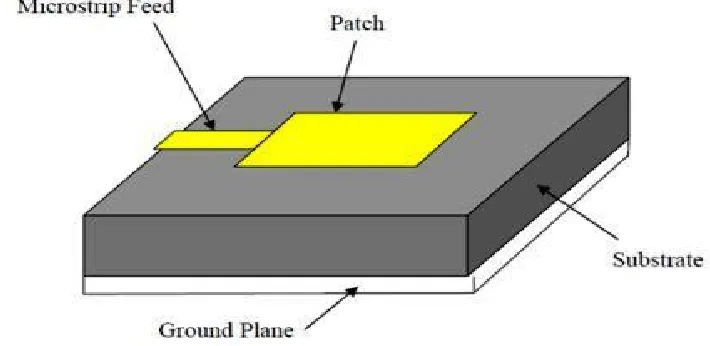
[image:3.612.153.465.285.443.2]The length of the patch is denoted by L and width of the patch is denoted by W. Because the dimensions of the patch are finite along the length and width, the fields at the edges of the patch undergo fringing. Since some of the waves travel in the substrate and some in air, an effective dielectric constant is introduced to account for fringing and the wave propagation in the line.
Figure 1 Basic Geometry of Circular Microstrip Patch Antenna
A. Microstrip Line Feed
It is the easiest of the feeding methods to fabricate as it is just a conducting strip connected to the patch and can be considered as an extension to the patch. The conducting strip is smaller as compared to the patch width and it has advantage that the feed can be etched on the same substrate to provide planer structure. The advantage of this technique is that there is no need for any additional matching element to match the impedance of the feed line to patch. However as the thickness of the dielectric substrate increases spurious radiation increases which limits the bandwidth.[25]
[image:3.612.133.488.546.719.2]III. DESIGNINGOF ANTENNA
A. Design of H-Shape Antenna using square patch using MSL feed
[image:4.612.98.515.127.258.2]In this design we introduce some rectangular slot in square patch to made H-Shape slot as according to reference paper and design a multi band antenna.
Figure 3 Square Patch antenna
[image:4.612.97.516.281.413.2]B. Observation from -10dB return loss
Figure 4 Return loss graph of square patch antenna
The Proposed antenna is resonating at Five frequencies means provide three band as described below:
1) Resonant frequency = 3.02 GHz at -16.80 dB( S-parameter)
2) Resonant frequency = 6.86 GHz at -17.25 dB( S-parameter)
3) Resonant frequency = 9.09 GHz at -25.30 dB( S-parameter)
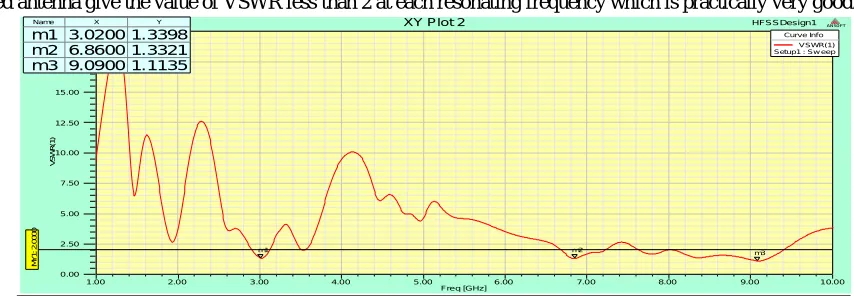
C. Observation from VSWR
[image:4.612.89.516.526.674.2]The proposed antenna give the value of VSWR less than 2 at each resonating frequency which is practically very good.
Figure 5 VSWR graph of square patch Antenna
1) VSWR at Resonant frequency 3.02 GHz is 1.33
2) VSWR at Resonant frequency 6.86 GHz is 1.33
3) VSWR at Resonant frequency 9.09 GHz is 1.11
1.00 2.00 3.00 4.00 5.00 6.00 7.00 8.00 9.00 10.00 Freq [GHz]
-30.00 -25.00 -20.00 -15.00 -10.00 -5.00 0.00
d
B
(S
(1
,1
))
HFSSDesign1
XY Plot 1 ANSOFT
M
Y
1
:
-1
0
.0
0
0
0
m1
m2
m3 Curve Info
dB(S(1,1)) Setup1 : Sw eep
Name X Y
m1 3.0270 -16.8048 m2 6.8468 -17.2526 m3 9.0991 -25.3093
1.00 2.00 3.00 4.00 5.00 6.00 7.00 8.00 9.00 10.00 Freq [GHz]
0.00 2.50 5.00 7.50 10.00 12.50 15.00 17.50 20.00
V
S
W
R
(1
)
HFSSDesign1
XY Plot 2 ANSOFT
M
Y
1
:
2
.0
0
0
0
m1 m2 m3
Curve Info VSWR(1) Setup1 : Sw eep Name X Y
D. Smith Chart
The smith chart curve of Proposed Antenna is shown in Figure.
[image:5.612.96.518.111.247.2]Impedance Matching at maximum VSWR frequency (9.09 GHz) = 0.9571 ×50= 47.85 ohm
Figure 6 Smith chart curve of square patch antenna
1) Design of rectangular patch antenna (H-Shape in Patch):
[image:5.612.63.526.286.429.2]In this design we introduce some rectangular slot in rectangular patch to made H-Shape slot as according to reference paper and design a multi band antenna.
Figure 7 Rectangular Patch antenna
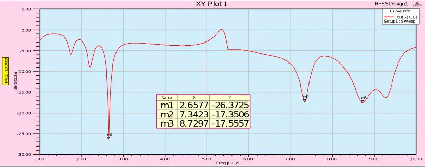
2) Observation from -10dB return loss
Figure 8 Return loss graph of rectangular patch antenna
The Proposed antenna is resonating at three frequencies means provide three band as described below:
a) Resonant frequency = 2.65 GHz at -26.37 dB (S-parameter)
b) Resonant frequency = 7.34 GHz at -17.35 dB (S-parameter)
c) Resonant frequency = 8.72 GHz at -17.55 dB (S-parameter)
E. Smith Chart
The smith chart curve of Proposed Antenna is shown in Figure.
5.00 2.00 1.00 0.50 0.20 0.00 5.00 -5.00 2.00 -2.00 1.00 -1.00 0.50 -0.50 0.20 -0.20 0.00 0 10 20 30 40 50 60 70 80 90 100 110 120 130 140 150 160 170 180 -170 -160 -150 -140 -130 -120 -110
-100 -90 -80 -70 -60 -50 -40 -30 -20 -10 HFSSDesign1
Smith Chart 1 ANSOFT
m1
Curve Info S(1,1) Setup1 : Sw eep Name Freq Ang Mag RX Q VSWR
m1 9.0901 -111.2412 0.0537 0.9571 - 0.0961i 0.1004 1.1135
1.00 2.00 3.00 4.00 5.00 6.00 7.00 8.00 9.00 10.00 Freq [GHz] -30.00 -25.00 -20.00 -15.00 -10.00 -5.00 0.00 5.00 d B (S (1 ,1 )) HFSSDesign1
XY Plot 1 ANSOFT
M Y 1 : -1 0 .0 0 0 0 m1 m2 m3 Curve Info dB(S(1,1)) Setup1 : Sw eep
Name X Y
[image:5.612.100.514.454.617.2]Impedance Matching at maximum VSWR frequency (2.65 GHz) = 0.9398 ×50= 46.99 ohm
Figure 9 Smith chart curve of rectangular patch antenna
F. Design of a H-Shape Antenna using circular patch
[image:6.612.95.519.294.481.2]In this design we introduce some rectangular slot in circular patch to made H-Shape slot as according to reference paper and design a multi band antenna.
Figure 10 Circular Patch antenna
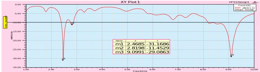
1) Observation from -10dB return loss
Figure 11 Return loss graph of circular patch antenna
The Proposed antenna is resonating at three frequencies means provide three band as described below:
a) Resonant frequency = 2.46 GHz at -31.16 dB( S-parameter)
b) Resonant frequency = 2.81 GHz at -11.45 dB( S-parameter)
c) Resonant frequency = 9.09 GHz at -29.08 dB( S-parameter)
2) Observation from VSWR
2.00 1.00 0.50 0.20
0.00 -20.00-10.00-5.00-3.00-2.00 0.00 0.00 4.00 -4.00 2.00 -2.00 1.00 -1.00 0.50 -0.50 0.20 -0.20 0.00 0 10 20 30 40 50 60 70 80 90 100 110 120 130 140 150 160 170 180 -170 -160 -150 -140 -130 -120 -110
-100 -90 -80 -70 -60 -50 -40 -30 -20 -10 HFSSDesign1
Smith Chart 1 ANSOFT
m1
Curve Info S(1,1) Setup1 : Sw eep Name Freq Ang Mag RX Q VSWR
m1 2.6577 -128.1024 0.0480 0.9398 - 0.0712i 0.0757 1.1009
1.00 2 .00 3 .0 0 4.0 0 5.00 6.00 7 .00 8 .0 0 9.0 0 1 0.0 0 Freq [GHz]
-3 5.0 0 -3 0.0 0 -2 5.0 0 -2 0.0 0 -1 5.0 0 -1 0.0 0 -5.0 0 0.0 0 d B (S (1 ,1 )) HFSSDesign1
XY Plot 1 ANSOFT
M Y 1 : -1 0 .0 0 0 0 m1 m2 m3 Curv e Inf o
dB( S( 1,1) ) Setup1 : Sw eep
Name X Y
m1 2.4685 -31.1686
m2 2.8198 -11.4529
[image:6.612.96.514.519.635.2]The proposed antenna give the value of VSWR less than 2 at each resonating frequency which is practically very good.
Figure 12 VSWR graph of circular patch Antenna
a) VSWR at Resonant frequency 2.46 GHz is 1.05
b) VSWR at Resonant frequency 2.81 GHz is 1.73
c) VSWR at Resonant frequency 9.09 GHz is 1.07
3) Smith Chart
The smith chart curve of Proposed Antenna is shown in Figure.
[image:7.612.98.519.307.422.2]Impedance Matching at maximum VSWR frequency (2.46 GHz) = 1.0473 ×50= 52.36 ohm
Figure 13 Smith chart curve of circular patch antenna
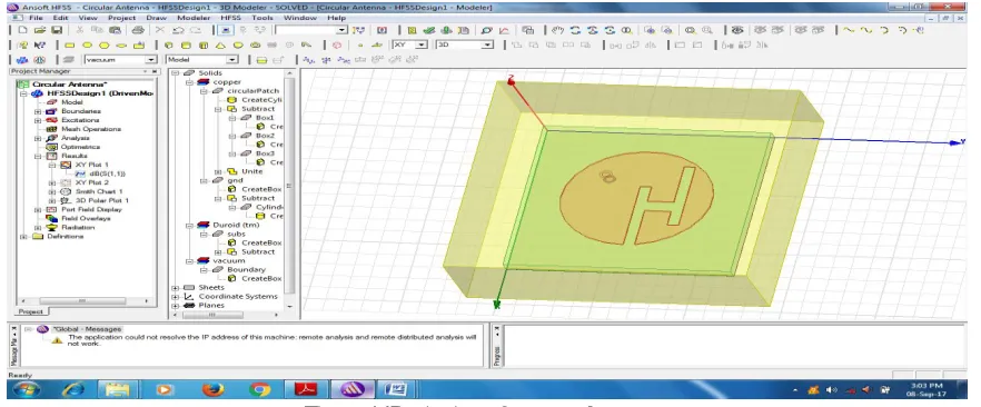
G. Design of Proposed H-Shape Circular Antenna using coaxial probe feed:
In this design we introduce some rectangular slot in patch to made H-Shape slot as according to reference paper and design a multi band antenna.
In this technique, microstrip patch antenna is designed using coaxial feed and three different dimension slot in patch detailed as shown below:
In this proposed design (H-Shape) the width of H slot is increased as compare to reference antenna and coaxial feed (in reference antenna).
Figure 14Designing of proposed antenna
1 .0 0 2.0 0 3 .00 4.0 0 5 .00 6 .00 7.0 0 8.00 9.0 0 1 0.0 0
Fre q [GHz] 0 .00 2 .50 5 .00 7 .50 10 .00 12 .50 15 .00 17 .50 20 .00 V S W R (1 ) HFSSDesign1
XY Plot 2 ANSOFT
M Y 1 : 2 .0 0 0 0 m1 m2 m3 Curv e Inf o
V SWR(1) Setup1 : Sw eep
Name X Y
m1 2.4685 1.0569
m2 2.8108 1.7302
m3 9.0900 1.0722
5.0 0 2.0 0 1 .00 0 .50 0 .2 0 0.00 5.00 -5.00 2.0 0 -2.00 1.0 0 -1.00 0.5 0 -0 .50 0 .2 0
-0.20 0.00 0 1 0 20 30 4 0 5 0 60 70 80 9 0 10 0 11 0 12 0 1 30 1 40 15 0 16 0 1 70 180 -1 70 -16 0 -15 0 -1 40 -1 30 -12 0 -11 0
-10 0 -90 -8 0 -7 0
-6 0 -50 -40 -3 0 -2 0 -10 HFSSDesign1
Smith Chart 1 ANSOFT
m1
Curv e Inf o
S( 1,1) Setup1 : Sw eep
Name Freq A ng Mag RX Q V SWR
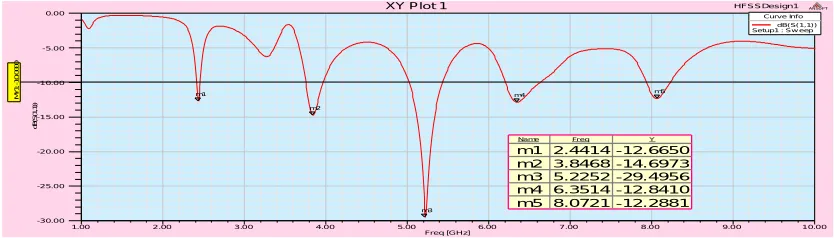
[image:7.612.88.529.541.724.2]1) ) Observation from -10dB return loss
Figure 15 Return loss graph of Proposed antenna
a) The Proposed antenna is resonating at Five frequencies means provide five band as described below:
4) Resonant frequency = 2.44 GHz at -12.66 dB( S-parameter)
5) Resonant frequency = 3.84 GHz at -14.69 dB( S-parameter)
6) Resonant frequency = 5.22 GHz at -29.49 dB( S-parameter)
7) Resonant frequency = 6.35 GHz at -12.84 dB( S-parameter)
8) Resonant frequency = 8.07 GHz at -12.28 dB( S-parameter)
2) Observation from VSWR
[image:8.612.82.520.255.458.2]The proposed antenna give the value of VSWR less than 2 at each resonating frequency which is practically very good.
Figure 16 VSWR graph of Proposed Antenna
a) VSWR at Resonant frequency 2.44 GHz is 1.60
b) VSWR at Resonant frequency 3.84 GHz is 1.45
c) VSWR at Resonant frequency 5.22 GHz is 1.06
d) VSWR at Resonant frequency 6.35 GHz is 1.59
e) VSWR at Resonant frequency 8.07 GHz at 1.64
3) Radiation Pattern:Radiation Pattern of proposed antenna shows that the antenna is highly directed in particular direction.
Figure 17 Radiation pattern curve of Proposed Antenna
1.00 2 .00 3 .0 0 4.0 0 5.00 6.00 7 .00 8 .0 0 9.0 0 1 0.0 0 Freq [GHz]
-3 0.0 0 -2 5.0 0 -2 0.0 0 -1 5.0 0 -1 0.0 0 -5.0 0 0.0 0
d
B
(S
(1
,1
))
HFSSDesign1
XY Plot 1 ANSOFT
M
Y
1
:
-1
0
.0
0
0
0
m1
m2
m3
m4 m5
Curv e Inf o dB( S( 1,1) ) Setup1 : Sw eep
Name Fr eq Y
m1 2.4414 -12.6650
m2 3.8468 -14.6973
m3 5.2252 -29.4956
m4 6.3514 -12.8410
m5 8.0721 -12.2881
1 .0 0 2.0 0 3 .00 4.0 0 5 .00 6 .00 7.0 0 8.00 9.0 0 1 0.0 0 Fre q [GHz]
0 .00 10 .00 20 .00 30 .00 40 .00 50 .00 60 .00 70 .00
V
S
W
R
(1
)
HFSSDesign1
XY Plot 2 ANSOFT
M
Y
1
:
2
.0
0
0
0
m1 m2 m3 m4 m5
Curv e Inf o
V SWR(1) Setup1 : Sw eep
Name X Y
m1 2.4414 1.6066
m2 3.8468 1.4514
m3 5.2252 1.0694
m4 6.3514 1.5907
4) Smith Chart:The smith chart curve of Proposed Antenna is shown in Figure.
[image:9.612.76.542.96.340.2]Impedance Matching at maximum VSWR frequency (5.22 GHz) = 1.007 ×50= 50.035 ohm
Figure 18 Smith chart curve of Proposed antenna
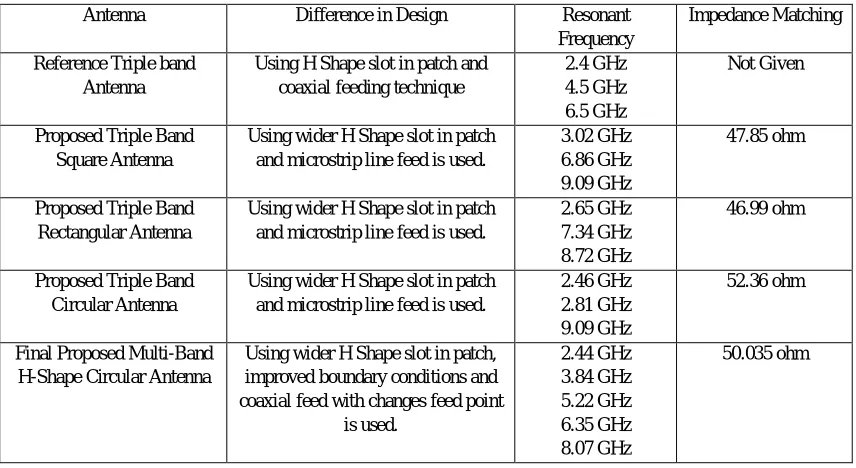
H. Conclusion between Reference Antenna and Proposed Multiband Antenna:
So the proposed antenna give the better result in terms of more multiband (5 bands as compare to reference antenna has 3 band), better S-Parameters, better VSWR and impedance matching.
Table 1 Difference Table between Reference and Proposed antenna
Antenna Difference in Design Resonant
Frequency
Impedance Matching
Reference Triple band Antenna
Using H Shape slot in patch and coaxial feeding technique
2.4 GHz 4.5 GHz 6.5 GHz
Not Given
Proposed Triple Band Square Antenna
Using wider H Shape slot in patch and microstrip line feed is used.
3.02 GHz 6.86 GHz 9.09 GHz
47.85 ohm
Proposed Triple Band Rectangular Antenna
Using wider H Shape slot in patch and microstrip line feed is used.
2.65 GHz 7.34 GHz 8.72 GHz
46.99 ohm
Proposed Triple Band Circular Antenna
Using wider H Shape slot in patch and microstrip line feed is used.
2.46 GHz 2.81 GHz 9.09 GHz
52.36 ohm
Final Proposed Multi-Band H-Shape Circular Antenna
Using wider H Shape slot in patch, improved boundary conditions and coaxial feed with changes feed point
is used. 2.44 GHz 3.84 GHz 5.22 GHz 6.35 GHz 8.07 GHz 50.035 ohm IV. CONCLUSION
A Multi-band Circular patch antenna with H shaped slot is designed using HFSS. The design exhibits five frequencies at 2.44 GHz, 3.84GHz, 5.22 GHz, 6.35 GHz, 8.07 GHz. The return loss, gain and radiation patterns were measured with the help of HFSS tool and tabulated. The design shows that the slot based bandwidth enhancement technique is simple and effective in the lower GHz frequencies. The impedance matching is very high 50.035 ohm which is very near about characteristic impedance.
5.00 2.00 1.00 0.50 0.20 0.00 5.00 -5.00 2.00 -2.00 1.00 -1.00 0.50 -0.50 0.20 -0.20 0.00 0 10 20 30 40 50 60 70 80 90 100 110 120 130 140 150 160 170 180 -170 -160 -150 -140 -130 -120 -110
-100 -90 -80 -70
-60 -50 -40 -30 -20 -10 HFSSDesign1
Smith Chart 1 ANSOFT
m1
Curve Info S(1,1) Setup1 : Sw eep
Name Freq Ang Mag RX Q VSWR
[image:9.612.93.521.420.654.2]VI. REFERENCES
[1] Rui Ma, Pei ZhengMengjiaLuo, Zhilei Wen, Houjun Sun, “Design of
[2] W band Dual Polarized Microstrip Patch Antenna” IEEE, 2014 3rd Asia-Pacific Conference on Antennas and Propagation.R.Bargavi, K.Sankar and S.Arivumani Samson , “Compact Triple band H-Shaped Slotted Circular Patch Antenna”, International Conference on Communication and Signal Processing IEEE, April 3-5,2014, India
[3] Sanjeevdwivedi and R.N.Yadav, “DESIGN OF U-SHAPE MICROSTRIP PATCH ANTENNA FOR WiMAX APPLICATIONS AT 2.5 GHz”, 978-1-4673-5999-3/13/2013 IEEE
[4] Wei-Chung Weng and Chia Liang Hung,2014. “An H-Fractal Antenna For Multiband Operations,”IEEE antenna and wireless communication letters, Vol 13. [5] SangeethaVelan, Ester Florence Sundersingh, MalathiKangasabai, Member,Aswathy K. Sarma, ChinnambetiRaviteja, RamprabhuSivasamy , and
JayaramKizhekkePakkathillam, 2015. “Dual-Band EBG Integrated Monopole Antenna Deploying Fractal Geometry For Wearable Applications,” IEEE antenna and wireless communication letters, Vol 14
[6] AmrollahAmini, homayoonOraizi, Mohammad Amin ChaychiZadeh, 2015. “Miniaturized UWB Log-Periodic Square Fractal Antenna,” IEEE antenna and wireless communication letters, Vol 14
[7] ShrivishalTripathi, Akhilesh Mohan, SandeepYadav, 2015. “ A Compact Kotch Fractal UWB MIMO Antenna With WLAN Band-Rejection,” IEEE antenna and wireless communication letters, Vol 14\
[8] Sangjun Ha and Chang Won Jung, “Single patch beam steering antenna with U-slot for wearable fabric application,” International Journal for Electronics and Communication pp. 653-659.20
[9] [9] T.Shanmuganantham, S.Raghavan, 2008. “Design Of a Compact Microstrip Patch Antenna With Probe Feeding for Wireless Applications,” International Journal for Electronics and Communication pp. 653-659.Udit Raithatha, S. SreenathKashyap& D. Shivakrishna, May 2015, “Swastika Shaped Microstrip Patch Antenna for ISM Band Applications” international journal IRJET.\
[10] Singh Bhatia, Jagtar Singh Sivian, ManpreetKaur, “Comparison of feeding techniques for the design of microstrip rectangular patch antenna for x-band applications”, International Journal of Advanced Technology in Engineering and Science, Volume No.03, Special Issue No. 02, 2015.\
[11] GurpreetKaur, Er. Sonia Goyal, “Effect of Height on Edge Tapered Rectangular Patch Antenna using Parasitic Stubs and Slots’’, International Journal of Engineering Trends and Technology (IJETT) – Volume 34 Number 8- April 2016.
[12] Alejandro Borja, “Reconfigurable Microwave Circuit Based on a Single Triangular Microstrip Patch” 978-1-4799-7815-1/15/2015 IEEE, Page No. 2253, AP-S 2015.\
[13] Chandra Bhan, Ajay Kumar Dwivedi, Brijesh Mishra, Anil Kumar, “Quad Bands U-shaped Slot Loaded Probe Fed Microstrip Patch Antenna”, IEEE, 2015 Second International Conference on Advances in Computing and Communication Engineering.
[14] R.K. Sharan, S.K. Sharma, “ A .Gupta, R.K Chaudhary, An Edge Tapered Rectangular Patch Antenna with Parasitic Stubs and Slot for Wideband Applications, Wireless PersCommunVol 86, pp 1213–1220, 2016.
[15] M. Tarikul Islam, M. Samsuzzaman, M. Z. Mahmud, M.T. Islam, “A Compact Spectacles Shaped Patch Antenna for UWB Applications”, 9th International Conference on Electrical and Computer Engineering, IEEE, 20-22 December, 2016, Dhaka, Bangladesh.\
[16] P.Surendra Kumar, B.Chandra Mohan, “Dual-Frequency Vertex-Fed Pentagonal Slot On Rectangular Patch For WLAN/WiMAX Applications”, 978-1-5090-3646/ 2016 IEEE.\