Abstract—A novel compact Ultra-Wideband Multiple Input Multiple Output (UWB-MIMO) antenna with enhanced bandwidth is proposed. The bandwidth of the designed antenna ranges from 1 to 30 GHz which covers L, S, C, X, Ku, K bands and some part of Ka-band. A square slot & inverse L-shaped strip is used to improve the isolation amid antenna elements. The suggested antenna achieves Mutual Coupling and Envelope Correlation Coefficient below−17 dB and 0.15, respectively. MIMO performance parameters like Mean Effective Gain is around 0 dB, and Total Active Reflection Coefficient is less than
−10 dB. The Channel Capacity Loss and Effective Diversity Gain are less than 0.3 bits/s/Hz and 9.2 dB, respectively. The radiation efficiency of the designed antenna is around 80% over the complete frequency range. The overall dimensions of designed antenna are 27×17×1.6 mm3.
1. INTRODUCTION
With the arrival of new wireless communication services, the demand for ultra-wideband with low cost and compact size is increasing tremendously. Wide bandwidth antennas are constantly in demand because a single wideband antenna can be used for a variety of applications. Ultra-wideband has the bandwidth from 3.1 to 10.6 GHz that can be used for various applications such as WiMAX, WLAN, and X-band Satellite Communication System. However, to access more applications like GPS, GSM, ISM, and Bluetooth, an enhanced bandwidth UWB monopole antenna is required [1]. Enhanced bandwidth UWB antenna can be designed using different techniques that are discussed in the literature. One of them is by inserting slots in the ground surface [2, 3]. The resonance of the slot combines with the resonance frequency of the antenna which enhances the bandwidth of the proposed structure [4, 5]. Different patch structures like Koch geometry [6], hexagonal shaped [7], lotus shaped [8], and crescent ring [9] are used to attain better impedance [10, 11] matching over a wider bandwidth. Electromagnetic bandgap [12–14] and parasitic element [15] are also used to achieve wider bandwidth.
Due to multipath environment, UWB antennas face the problem of signal fading [16]. To avoid the problem, ultra-wideband Multiple input multiple output (MIMO) antenna is designed. UWB-MIMO antenna also provides improved channel capacity. However, UWB-UWB-MIMO has an issue of mutual coupling amid antenna elements. Antenna performance is affected due to low isolation amid antenna elements. To improve isolation various techniques such as Defective Ground Structures (DGS) [17], 90◦ angular separation [18], split-ring resonators [19], neutralization line [20], polarization diversity [21], and decoupling strips [22] are used.
In this paper, a novel compact UWB-MIMO antenna with enhance bandwidth is presented. A square slot and an inverse L-shaped strip are used to improve the isolation amid antenna elements. Therefore, the proposed antenna design is a suitable candidate for a variety of applications like GSM/UMTS (1800/1900/2100 MHz), GPS (1227.60/1575.42 MHz), ISM (2.4/24.25 GHz), WLAN/WiFi (3.6/4.9/5/5.9 GHz), radio applications (13.4–14 GHz), UWB communication (3.1–10.6 GHz), radio astronomy (22.5 GHz, 24.05–27 GHz), and 5G (27.5–28.35 GHz).
Received 30 August 2019, Accepted 19 November 2019, Scheduled 29 November 2019 * Corresponding author: Naveen Jaglan ([email protected]).
2. PROPOSED UWB MIMO ANTENNA WITH ENHANCED BANDWIDTH 2.1. UWB-MIMO Antenna Design
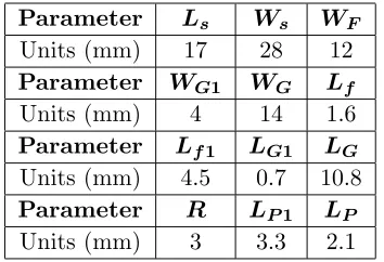
The dimensions of the suggested antenna are illustrated in Figure 1, and the design parameters are given in Table 1. The antenna is designed on a low-cost Flame Retardant (FR)-4 substrate having dielectric constant (εr), substrate height (h), and loss tangent of 4.4, 1.6 mm, and 0.02, respectively. Radiating patch is fed using 50-ohm microstrip line. A square slot is etched, and an inverse L-shaped strip is attached with a ground plane to improve the isolation. Simulated results are obtained using Ansoft HFSS v.13 software. The proposed antenna is fabricated using EP 2006 PCB prototype machine. Scattering parameters of the antenna are measured with Agilent N5230C vector network analyzer. The radiation pattern and gain of the antenna are measured in a microwave shield anechoic chamber. The layout of the fabricated UWB-MIMO antenna is illustrated in Figure 2. Figure 3 indicates the simulated and tested VSWRs of the suggested antenna. The values ofR1,LS,WS,LP, andLP1are parametrically tuned to get an impedance bandwidth of 29 GHz (1–30 GHz), which covers the entire frequency range. The difference between measured and simulated parameters is due to various losses like conduction loss, dielectric loss, mismatch loss, SMA soldering, fabrication and measurement error.
Figure 1. Suggested UWB-MIMO antenna with enhanced bandwidth.
Table 1. Dimensions of suggested antenna.
Parameter Ls Ws WF
Units (mm) 17 28 12
Parameter WG1 WG Lf
Units (mm) 4 14 1.6
Parameter Lf1 LG1 LG
Units (mm) 4.5 0.7 10.8
Parameter R LP1 LP
(a) (b)
Figure 2. (a) Upper view, (b) back view of the fabricated suggested antenna.
Figure 3. Tested and simulated VSWR of the suggested antenna.
2.2. Effect of Variations in the Ground Plane of the Suggested Antenna
The performance properties like antenna impedance and radiation properties of the proposed antenna are significantly dependent on the ground plane [16, 23, 24]. Figure 4 displays the stepwise expansion of the ground plane. Figure 5 illustrates the mutual coupling of different ground planes, and it is observed
Ground A Ground B Ground C
that the best performance can be obtained using ground C. Hence, Ground C is used with the proposed enhanced bandwidth UWB-MIMO antenna. Figure 6 illustrates the mutual coupling among radiating elements of the suggested antenna.
Figure 5. Variation of the ground plane. Figure 6. Measured and simulated mutual coupling.
(a)
(c)
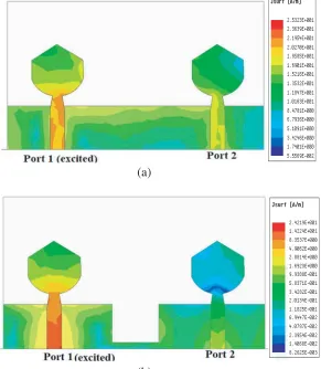
Figure 7. Distribution of the surface current on the suggested antenna.
(a) (b)
(c) (d)
Figure 7 shows the effectiveness of the decoupling structure in the ground plane. It is observed in Figure 7(a) that surface current flows from port 1 to port 2 thereby resulting in poor isolation.
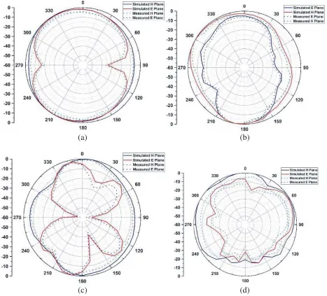
The mutual coupling among antenna elements is decreased by etching square slot on the ground surface as depicted in Figure 7(b). However, the addition of an inverse L-shaped strip greatly decreases the mutual coupling as shown in Figure 7(c). Figures 8(a), (b), and (c) depict tested and simulated radiation pattern plots at four different frequencies.
3. RESULTS AND DISCUSSION
Two Element MIMO antenna is used to provide higher data throughput [25–28]. The design of the MIMO antenna is a challenging task, as the antenna elements are placed at very close proximity. Due to this the port coupling and field coupling increase. These couplings affect the efficiency and channel capacity of the proposed antenna. Therefore, there is a requirement of high port isolation and low correlation level. MIMO performance characteristics such as Envelope Correlation Coefficient (ECC) [29], Diversity Gain (DG) [28], Total Active Reflection Coefficient (TARC) [12], Effective Diversity Gain (EDG), Radiation Efficiency (RE), and Channel Capacity Loss (CCL) of the suggested MIMO antenna are calculated. The amount of correlation [30] between the radiation patterns of MIMO elements can be evaluated using ECC. The ECC of the two-port antenna [29] systems can be given by:
ECC =
Ω
XPR·EθiEθj∗ Pθ+EφiEθj∗ Pφ
dΩ2
Ω
XPR·EθiEθi∗Pθ+EφiEφi∗ Pφ
dΩX Ω
XPR·EθjEθj∗ Pθ+EθjEθj∗Pφ
dΩ
(1)
XPR is the cross-polarization rate of the incident field.
XPR = PV
PH
where PV and PH are the average power along elevation (θ) and azimuthal angle (Φ). ECC [31] can also be expressed in terms of S parameters:
ECC = |S11∗ S12+S21∗ S22| 2
1− |S11|2− |S21|2 1− |S22|2− |S12|2
(2)
where S11 and S22 are the reflection coefficients. S12 and S21 are coupling between the two ports. It is necessary to have ECC<0.5 for acceptable performance of a MIMO antenna. Diversity gain (DG) is defined as the difference between the power level in dB of the combined signal within the diversity antenna system and that of a single antenna system in one diversity channel. Diversity Gain [32] of the suggested antenna is calculated as:
DG = 101−ECC2 (3)
Figure 9 indicates the tested and simulated ECC and DG of the suggested antenna. Another important MIMO characteristic is Effective Diversity Gain (EDG). The DG does not consider radiation losses of the antenna whereas EDG includes radiation losses. The EDG formula is given below in Equation (4). The product of DG with radiation efficiency yields EDG. As radiation losses are multiplied with the DG, the EDG will be less than the DG values. The average value of DG is around 9.98 dB whereas EDG is around 9.2 dB.
EDG = ηTotal∗DG (4)
ηTotal = η
1− |S11|2− |S21|2
(5)
Figure 9. Tested and simulated variation of ECC and DG with frequency.
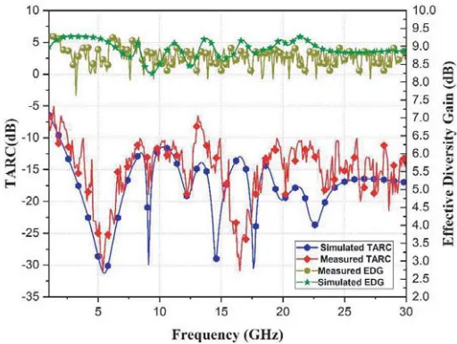
Figure 10. Tested and simulated TARC and EDG.
signal as shown in Equation (6) [34].
TARC = N i=1
|bi|2
N i=1
|ai|2
(6)
whereai andbi are the forward traveling signal and backward traveling signal, respectively. The TARC of the two-port antenna can be described usingS-parameters as given below [34].
TARC = (S11+S12) 2
+ (S21+S22)2
2 (7)
9.2 dB. With compact size and high isolation, radiation efficiency for UWB MIMO is around 80% in the operation band of the UWB system. In a fading environment, MEG is the difference between the power received by the antenna elements and that of an isotropic antenna. The mean effective gain [35–38] is evaluated using Equations (8) and (9). So, MEGi and MEGj are calculated as [35]
MEGi= 0.5 ⎡ ⎣1−
N
j=1
|Sij|2 ⎤
⎦<−3 dB (8)
Also, |MEGi−MEGj|<3 dB (9)
MEGi= 0.5
1− |S11|2− |S12|2
(10)
MEGj = 0.5
1− |S21|2− |S22|2
(11)
where i, j denote antenna elements 1 and 2, respectively. Figure 11 shows the MEG for the suggested antenna. To determine the performance of the MIMO system, one of the important parameters is
Figure 11. MEGs of two antenna elements. Figure 12. Channel capacity loss vs frequency.
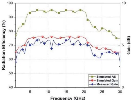
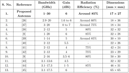
operating range. Figure 13 represents the tested gain and radiation efficiency. Table 2 indicates that the suggested antenna has compact size and enhanced bandwidth compared to other antennas mentioned in the literature.
Table 2. Comparison of the suggested antenna with the existing antenna in the literature.
S. No. Reference Bandwidth (GHz)
Gain (dBi)
Radiation Efficiency (%)
Dimensions (mm×mm) 1. Proposed
Antenna 1–30 6 Around 85% 17×27
2. [26] 2.9–20 1.6 to 6 Around 60% 18×36
3. [37] 3–20 0 to 7 Around 75% 18×34
4. [38] 2–12 5 80% 32×32
5. [8] 1–20 6 85% 32×28
6. [39] 1–14 5 Around 85% 30×10
7. [40] 2–12 5.5 - 22×26
8. [41] 2–12 4 75% 42×24
9. [42] 2–12 4 75% 23×29
10. [9] 2–16 3.5–6 80% 50×30
11. [43] 3.1–13.6 4.5 - 32×32
12. [44] 3.1–17.3 1–5 85% 46×31
13. [45] 3.1–17.5 6 - 65×65
4. CONCLUSION
A compact size and high efficiency UWB MIMO antenna is designed and fabricated. The suggested antenna has an operational impedance bandwidth from 1 to 30 GHz for various applications like GPS, GSM1800, ISM, Bluetooth, WLAN, and radio astronomy. The suggested antenna shows good diversity performance with ECC<0.2 and CCL<0.3. The DG is around 9.98, TARC<−10.5 dB, and radiation efficiency is around 80%. The measured results show good resemblance to simulated ones.
ACKNOWLEDGMENT
REFERENCES
1. Ali, T., S. B K, and R. C. Biradar, “A miniaturized decagonal Sierpinski UWB fractal antenna,”
Progress In Electromagnetics Research C, Vol. 84, 161–174, 2018.
2. Nguyen, D. T., D. H. Lee, and H. C. Park, “Very compact printed triple band-notched UWB antenna with quarter-wavelength slots,”IEEE Antennas and Wireless Propagation Letters, Vol. 11, 411–414, 2012.
3. Chattopadhyay, K., S. Das, S. Das, and S. R. Bhadra Chaudhuri, “Ultra-wideband performance of printed hexagonal wide-slot antenna with dual band-notched characteristics,” Progress In Electromagnetics Research C, Vol. 44, 83–93, 2013.
4. Alkhatib, R. and M. Drissi, “Improvement of bandwidth and efficiency for directive superstrate EBG antenna,” Electronics Letters, Vol. 43, 696–702, 2007.
5. Chamani, Z. and S. Jahanbakht, “Improved performance of double-T monopole antenna for 2.4/5.6 GHz dual-band WLAN operation using artificial magnetic conductors,” Progress In Electromagnetics Research M, Vol. 61, 205–213, 2017.
6. Tripathi, S., S. Yadav, and A. Mohan, “Hexagonal fractal ultra-wideband antenna using Koch geometry with bandwidth enhancement,”IET Microwaves, Antennas &Propagation, Vol. 8, 1445– 1450, 2014.
7. Irene, G. and A. Rajesh, “A penta-band reject inside cut koch fractal hexagonal monopole UWB MIMO antenna for portable devices,” Progress In Electromagnetics Research C, Vol. 82, 225–235, 2018.
8. Elwi, T. A., A. I. Imran, and Y. Alnaiemy, “A miniaturized lotus shaped microstrip antenna loaded with ebg structures for high gain-bandwidth product applications,” Progress In Electromagnetics Research C, Vol. 60, 157–167, 2015.
9. Kumar, A., A. Q. Ansari, B. K. Kanaujia, J. Kishor, and N. Tewari, “Design of triple-band MIMO antenna with one band-notched characteristic,” Progress In Electromagnetics Research C, Vol. 86, 41–53, 2018.
10. Thakur, E., N. Jaglan, S. D. Gupta, and B. K. Kanaujia, “A compact notched UWB MIMO antenna with enhanced performance,” Progress In Electromagnetics Research C, Vol. 91, 39–53, 2019.
11. Zhang, Y. P., “60-GHz antenna-in-package technology,”IET Microwaves, Antennas&Propagation, Vol. 5, 1743–1750, 2011.
12. Guo, Z., H. Tian, X. Wang, Q. Luo, and Y. Ji, “Bandwidth enhancement of monopole UWB antenna with new slots and ebg structures,” IEEE Antennas and Wireless Propagation Letters, Vol. 12, 1550–1553, 2013.
13. Chen, D., W. Yang, and W. Che, “High-gain patch antenna based on cylindrically projected EBG planes,” IEEE Antennas and Wireless Propagation Letters, Vol. 17, 2374–2378, 2018.
14. Huang, C., C. Ji, X. Wu, J. Song, and X. Luo, “Combining FSS and EBG surfaces for high-efficiency transmission and low-scattering properties,” IEEE Transactions on Antennas and Propagation, Vol. 66, 1628–1632, 2018.
15. Ghimire, J., K. Choi, and D. Y. Choi, “Bandwidth enhancement and mutual coupling reduction using a notch and a parasitic structure in a UWB-MIMO antenna,” International Journal of Antennas and Propagation, Vol. 15, 1–9, 2019.
16. Alrabadi, O. N., J. Perruisseau-Carrier, and A. Kalis, “MIMO transmission using a single RF source: Theory and antenna design,” IEEE Transactions on Antennas and Propagation, Vol. 60, 654–664, 2012.
17. Zhu, J., B. Feng, B. Peng, L. Deng, and S. Li, “A dual notched band MIMO slot antenna system with Y-shaped defected ground structure for UWB applications,”Microvave and Optical Technology Letters, Vol. 58, 626–630, 2016.
MIMO antenna with mutual coupling reduction,”Progress In Electromagnetics Research C, Vol. 91, 55–67, 2019.
23. Braaten, B. D., A. Iftikhar, A. D. Capobianco, B. Ijaz, S. Asif, and M. S. Khan, “Compact 4×4 UWB-MIMO antenna with WLAN band rejected operation,” Electronics Letters, Vol. 51, 1048– 1050, 2015.
24. Chiu, C.-Y., J.-B. Yan, and R. D. Murch, “Compact three-port orthogonally polarized MIMO antennas,”IEEE Antennas and Wireless Propagation Letters, Vol. 6, 619–622, 2007.
25. Park, J., J. Choi, J. Park, and Y. Kim, “Study of a T-shaped slot with a capacitor for high isolation between MIMO antennas,”IEEE Antennas and Wireless Propagation Letters, Vol. 11, 1541–1544, 2012.
26. Chandel, R., A. K. Gautam, and K. Rambabu, “Tapered fed compact UWB MIMO-diversity antenna with dual band-notched characteristics,” IEEE Transactions on Antennas and Propagation, Vol. 66, 1677–1684, 2018.
27. Fletcher, P. N., M. Dean, and A. R. Nix, “Mutual coupling in multi-element array antennas and its influence on MIMO channel capacity,” Electronics Letters, Vol. 39, 336–342, 2003.
28. Karaboikis, M. P., V. C. Papamichael, G. F. Tsachtsiris, C. F. Soras, and V. T. Makios, “Integrating compact printed antennas onto small diversity/MIMO terminals,”IEEE Transactions on Antennas and Propagation, Vol. 56, 2067–2078, 2008.
29. Kaiser, T., F. Zheng, and E. Dimitrov, “An overview of ultra-wide-band systems with MIMO,”
Proceedings of the IEEE, Vol. 97, 285–312, 2009.
30. Jaglan, N., B. K. Kanaujia, S. D. Gupta, and S. Srivastava, “Design of band-notched antenna with DG-CEBG,”International Journal of Electronics, Vol. 105, 58–72, Jan. 2018.
31. Mao, C. and Q. Chu, “Compact coradiator UWB-MIMO antenna with dual polarization,” IEEE Transactions on Antennas and Propagation, Vol. 62, 4474–4480, 2014.
32. Suwailam, M. M., B. M. S. Boybay, and O. M. Ramahi, “Electromagnetic coupling reduction in high-profile monopole antennas using single-negative magnetic metamaterials for MIMO applications,” IEEE Transactions on Antennas and Propagation, Vol. 58, 2894–2902, 2010. 33. Yu, K., Y. Li, and X. Liu, “Mutual coupling reduction of a MIMO antenna array using 3-D novel
meta-material structures,” IEEE Transactions on Antennas and Propagation, Vol. 33, 1–7, 2018. 34. Jaglan, N. and S. D. Gupta, “Design and analysis of performance enhanced microstrip patch
antenna with EBG substrate,”International Journal of Microwave and Optical Technology, Vol. 10, No. 2, 79–88, 2015.
35. Glazunov, A. A., A. F. Molisch, and F. Tufvesson, “Mean effective gain of antennas in a wireless channel,”IET Microwaves, Antennas &Propagation, Vol. 3, 101–114, 2009.
36. Blanch, S., J. Romeu, and I. Corbella, “Exact representation of antenna system diversity performance from input parameter description,” Electronics Letters, Vol. 39, 701–705, 2003. 37. Chandel, R. and A. K. Gautam, “Compact MIMO/diversity slot antenna for UWB applications
with band-notched characteristic,” Electronics Letters, Vol. 52, No. 5, 336–338, 2016.
38. Ren, J., W. Hu, Y. Yin, and R. Fan, “Compact printed MIMO antenna for UWB applications,”
39. Ferrero, F., R. Addaci, R. Staraj, T. Fortaki, D. Seetharamdoo, and N. Hamdiken, “Simple bandwidth-enhancement technique for miniaturised low-profile UWB antenna design,” Electronics Letters, Vol. 50, 1564–1566, 2014.
40. Ranga, Y., A. K. Verma, K. P. Esselle, and S. G. Hay, “An ultra-wideband quasi-planar antenna with enhanced gain,”Progress In Electromagnetics Research C, Vol. 49, 59–65, 2014.
41. Alsath, M. G. N. and M. Kanagasabai, “Compact UWB monopole antenna for automotive communications,”IEEE Transactions on Antennas and Propagation, Vol. 63, 4204–4208, 2015. 42. Khan, M. S., A.-D. Capobianco, S. M. Asif, D. E. Anagnostou, R. M. Shubair, and B. D. Braaten,
“A compact CSRR-enabled UWB diversity antenna,” IEEE Antennas and Wireless Propagation Letters, Vol. 16, 808–812, 2017.
43. Irene, G. and A. Rajesh, “A penta-band reject inside cut koch fractal hexagonal monopole UWB MIMO antenna for portable devices,” Progress In Electromagnetics Research C, Vol. 82, 225–235, 2018.
44. Kayabasi, A., A. Toktas, E. Yigit, and K. Sabanci, “Triangular quad-port multi-polarized UWB MIMO antenna with enhanced isolation using neutralization ring,”AEU — International Journal of Electronics and Communications, Vol. 85, 47–53, 2018.