2018 3rd International Conference on Computational Modeling, Simulation and Applied Mathematics (CMSAM 2018) ISBN: 978-1-60595-035-8
Research on the Control System of Indoor Cleaning Robots Based on
LED Optical Communication
Jin-peng WANG, Shu-fang ZHANG* and Yi JIANG
School of Information Science and Engineering, Dalian Maritime University, Dalian 116034, China *Corresponding author
Keywords: Led, Optical, Light communication.
Abstract. In order to realize the control of indoor cleaning robot, a design scheme of wireless
communication technology based on white LED is proposed. The system between the host computer and indoor cleaning robot is through the white LED to achieve wireless communication. Through the host computer control interface, to the indoor cleaning robot to send control instructions to achieve the clean robot wireless remote control. The system can be widely used in any place under the white LED coverage, can basically realize the local control platform through the white wireless communication to the control of the clean robot, but also to meet the public for the visible light intelligent control system of the expectations and basic needs.
Introduction
In recent years, with the rapid development of computer technology and the concept of intelligent home, family service intelligent products become an indispensable part of comfortable life, service robot has become a hot spot in the field of modern intelligent robot research [1-4]. But for the development of home service robot is still in its infancy, especially indoor cleaning robot, as the most basic home service equipment, our daily life and work to bring a lot of convenience, has become an indispensable part of life [5-6].
Indoor floor cleaning is a boring repetitive labor, and the work process is cumbersome, not only labor, and low efficiency, the traditional vacuum cleaner work requires not only people involved, and the operation of inconvenience, cleaning efficiency is low, the effect is poor, Indoor floor cleaning robot will be mobile robot technology and vacuum cleaner technology organic integration, to achieve indoor environment semi-autonomous cleaning, with good application prospects and a wide range of market demand [7].
At present, the control of indoor equipment is WiFi, Zigbee, Bluetooth, infrared, etc., mainly through the use of radio frequency technology to communicate [8], to achieve the intelligent control of equipment [9]. Emerging wireless Communication technology--the Visible Light Communication (VLC) used in intelligent control, compared with the traditional wireless Communication mode has many advantages [10]. VLC technology uses white LED not only to achieve dual-function lighting and communications will not produce any radio frequency interference, Interference by other wireless devices is also small [11-13]. In this paper, we design a kind of indoor cleaning robot control method based on visible light communication to complete the walking and vacuuming work. The control system based on visible light communication is studied by using the single chip microcomputer as the control chip. The whole system control platform can be applied to any white LED local, and not subject to electromagnetic interference, with unlimited application value and development space [14].
System Model
minimum system platform of the computer. The program receives the user instruction control The modules work. At the same time, the program also includes the modulation and demodulation of the transmitted data for data encoding transmission and reception decoding.
Host Computer MCU -control circuit LED signal transmission circuit USB Send Power Supply Power Supply
Power supply circuit modulation Emit module
Power supply circuit Signal amplifier receiving circuit MCU -Control circuit Send Cleaning Robot Send Power
Supply SupplyPower
Receive module
[image:2.595.174.422.118.267.2]Emit
Figure 1. The block diagram of system.
The transmitter includes MCU control unit, LED coded transmitter unit, power supply circuit and host computer. The host computer will control the instruction information, for example, let the cleaning robot "turn left" instruction sent through the USB interface to the MCU, MCU will be the instruction encoding, encoding using the key switch modulation (OOK), MCU will be encoded after The instruction data is transferred to the LED transmission circuit through the IO port, and the encoded data (electrical signal) is converted by the LED to the optical signal.
The receiving end comprises an MCU control unit, a photodiode decoding unit, a signal amplifying circuit, a power supply circuit and a cleaning robot module. The photodiode converts the received optical signal transmitted by the transmitting module into an electrical signal, transmits the electrical signal to the MCU through the IO port, the MCU demodulates the received electrical signal, transfers the demodulated data through the MCU to the cleaning The robot's motor drives to control the cleaning robot wheel to turn left.
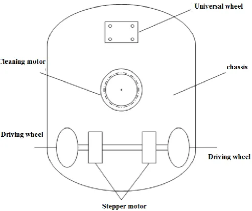
Figure 2. The structure of cleaning robot.
[image:2.595.174.421.487.693.2]cloth installed under the shell to remove the small dust remaining on the ground. Wheel motor, vacuum motor are used brushless DC motor.
[image:3.595.149.448.121.214.2]The visible light communication system transmission process is shown below.
Figure 3. Working principle diagram of visible light communication system.
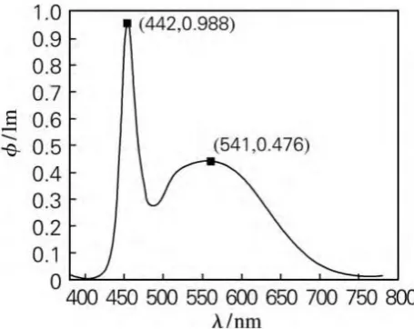
The system light source uses 3W 3beads of high power ordinary white LED as a signal source, the performance parameters are: rated voltage 9V, light angle of 600~1200, color temperature 6000~6500K. The photosensitive detector uses a photodiode area of 6*6mm2, can receive a spectral range of 300-1000nm (covering the whole visible light spectrum), the peak wavelength of 600nm photodiode. Figure 4 shows the white LED emission spectrum measured by integrating sphere. It can be seen that the spectrum emitted by the white LED light source mainly includes the blue light emitted by the LED itself at 442nm peak and the yellow light excited by the phosphor at 541nm. It can be seen from the figure that the maximum sensitivity of the photoelectric detector selected in this experiment is just near the peak wavelength of the spectral distribution of the light source.
Figure 4. The spectral distribution of white LED System.
The System Software Design
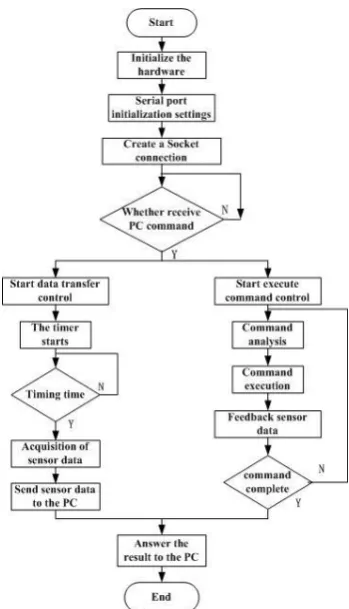
[image:3.595.184.412.376.557.2]Figure 5. System software diagram.
Summary
In order to realize the control of indoor clean robot, a design scheme of wireless communication technology based on white light LED was used to design the system. By analyzing the control method of indoor cleaning robot, the results of table 1 are shown in the comparison of all kinds of wireless communication channels. The experimental results show that VLC is applied to the control direction of indoor clean robot, and has a strong advantage in electromagnetic sensitive field. With the development of visible light communication technology, the intelligent control based on white LED wireless communication will become a new research hotspot. In particular, the application of visible light communication technology to intelligent control is of great significance and will be of great value in the field of intelligent services.
Acknowledgement
This research was financially supported by Project of the National Natural Science Foundation of China (61402069), “ the Fundamental Research Funds for the Central Universities”(3132016317), 2017 Project of the Natural Science Foundation of Liaoning province (20170540059),General project of Liaoning education department in 2016(2016J205).
References
[1] J. Tao and Y. Wu, “An Overview: Peak-to-Average Power Ratio Reduction Techniques for OFDM Signals,” IEEE Trans. Broadcast., vol. 54, no. 2, June 2008, pp. 257-268.
[3] S.H. Müller and J.B. Huber, “A Novel Peak Power Reduction Scheme for OFDM,” Proc. IEEE PIMRC, Helsinki, Finland, Sept. 1997, pp. 1090-1094.
[4] D.W. Lim et al., “A New SLM OFDM Scheme with Low Complexity for PAPR Reduction,” IEEE Signal Process. Lett., vol. 12, no. 2, Feb. 2005, pp. 93-96.
[5] C.L. Wang and Y. Ouyang, “Low-Complexity Selected Mapping Schemes for Peak-to-Average Power Ratio Reduction in OFDM Systems,” IEEE Trans. Signal Process., vol. 53, no. 12, Dec. 2005, pp. 4652-4660.
[6] C.L. Wang and S.J. Ku, “Novel Conversion Matrices for Simplifying the IFFT Computation of an SLM-Based PAPR Reduction Scheme for OFDM Systems,” IEEE Trans. Commun., vol. 57, no. 7, July 2009, pp. 1903-1907.
[7] G. Lu, P. Wu, and D. Aronsson, “Peak-to-Average Power Ratio Reduction in OFDM Using Cyclically Shifted Phase Stages,” IET Commun., vol. 1, no. 6, Dec. 2007, pp. 1146-1151.
[8] G. Hill, M. Faulkner, and J. Singh, “Cyclic Shifting and Time Inversion of Partial Transmit Stages to Reduce the Peak-to-Average Power Ratio in OFDM,” Proc. IEEE PIMRC, London, UK, Sept. 2000, pp. 1256-1259.
[9] B. Sklar, “A primer on turbo code concepts”, IEEE Communications Magazine, pp. 94-101, Dec. 1997.
[10] S. Lin and D. J. Costello, Jr., Error control coding: Fundamentals and applications, Prentice Hill, 1983.
[11] Jun Ma, Adv. Mater Research 2014:Vol.971–973 718-721
[12] T. Wang, Video Engineering 2013: 09 61
[13] D.Q. Ding, X.Z. Ke, Journal of Xi’an University of Technology 2007:01 29-33