2018 International Conference on Information, Electronic and Communication Engineering (IECE 2018) ISBN: 978-1-60595-585-8
Design and Application of a Flexible Test System for Relay
Communication Terminals
Hao RAO
1,2, Xian-feng LIANG
2,*and Jin-zhou ZHANG
31
National Space Science Center, Chinese Academy of Sciences, Beijing 100190, China
2
University of Chinese Academy of Sciences, Beijing 100190, China
3
Huawei Technologies Co., LTD, Beijing 100085, China
*Corresponding author
Keywords: Relay communication terminal, Flexible test system, General hardware platform, Special software.
Abstract. In order to test the functions and performance of the satellite relay communication terminal comprehensively before the satellite access network test and satellite relay communication test, a flexible automatic test system based on general hardware platform and special software was designed with electronic, communication, computer and network technologies. The testing system can provide equipment testing capability such as bit error rate, modulation signal quality and sensitivity analysis. The practical application results show that the flexible test system of relay communication terminal has the characteristics of complete function, simple operation, accurate result, stable and reliable, which is suitable for application in practical engineering.
Introduction
The test of satellite-relay communication terminal is to measure the function and performance of relay communication terminal comprehensively. The aim is to ensure that the parameters of relay communication terminal can meet the test outline of satellite access network and maintain long-term reliable work[1]. As the communication system involves various technical indexes about RF and low frequency, the traditional manual testing method has many disadvantages such as long test time, non-standard data processing, large influence of human factors, difficulty in analyzing test results and longtime microwave radiation[2]. Therefore, it is necessary to use automatic test system for communication terminal test[3].
The automatic testing system has experienced the evolution process from the special type to the general type. The general testing system overcomes the problem that the special testing system is not adaptable and no way to share resources. However, the general test system has some disadvantages such as large size, inconvenient maintenance, poor flexibility, and lots of resource redundancy. Therefore, it is the future development trend to design an open flexible test system[4] that can solve the problems such as complex structure, poor flexibility, huge volume and inconvenient maintenance of the current communication terminal test system, which can meet the requirements of different communication terminal tests.
This paper aims to design an open flexible test system, developing special software on the general hardware platform, and provide data link simulation and comprehensive test platform for communication terminal. The test system can provide equipment testing capability such as bit error rate, modulation signal quality, sensitivity analysis, etc.
Flexible Test System Design
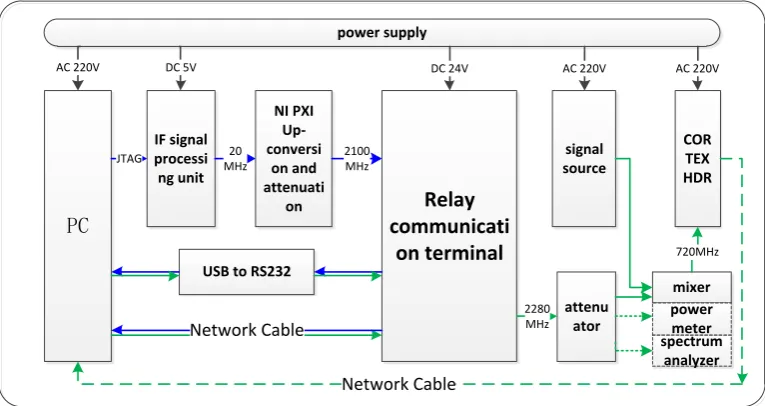
shore-based station → satellite → relay communication terminal is the forward link of satellite-relay communication. The link between relay communication terminal → satellite → shore-based station is called satellite relay backward link. The test of relay communication terminal is actually realized by testing the communication parameters of forward and backward link. The relay communication terminal test platform is shown in figure 1, where the blue signal flow is forward link and the green signal flow is backward link.
Relay communicati on terminal IF signal processi ng unit NI PXI Up-conversi on and attenuati on
USB to RS232 PC mixer signal source COR TEX HDR power supply
AC 220V AC 220V
AC 220V DC 5V DC 24V
[image:2.595.104.487.165.368.2]JTAG 20 MHz 2100 MHz Network Cable 720MHz 2280 MHz Network Cable attenu ator power meter spectrum analyzer
Figure 1. Relay communication terminal test platform.
In the forward test link, the PC updates the program of the simulated satellite forward signal to FPGA of the intermediate frequency signal processing unit through JTAG simulator, and sends the analog signals of carrier 20MHz and baseband bandwidth 3.069MHz to the upper frequency converter of NI PXI for up-conversion and attenuation, generating the 2100MHz RF modulation signal. After decoding, relay communication terminal sends parameter data and remote data to PC through serial port and network port respectively. After the PC receives the original remote control data through the network port, the BES tool is used to detect the error bits of the sent and received data. The above is the closed loop test of the forward link.
In the backward test link, PC use serial port and network port assistant to simulate sending state data and buoy data to relay communication terminal. The communication terminal packages, sets of frames, codes, interleaving, perturbation, modulation and amplification of the Data and then conducts power measurement after 30dB attenuator or generates 720MHz IF signal after mixing frequency, which is sent to the cortex HDR (High Data Rate Receiver) equipment to complete the demodulation, decoding and data storage. The data can also be transmitted to PC through the network line in real time for decode and BER test. The above is the closed loop test of the backward link.
and attenuator with LO(local oscillator), providing digital control interface. The control software is written by Labview which is the graphical programming language, the frequency of LO is adjustable, and the output attenuation is adjustable. The software interface is shown in figure 2. PXI-5670 converts the frequency of the 20MHz IF modulation signal into the RF modulation signal of 2100MHz. After attenuation, it is connected to the diplexer receiving port of relay communication terminal, which is suitable for the wired test in the laboratory.
Figure 2. Upconverter and attenuator control interface.
The forward BER test uses the BES general software to compare the forward data received from the network port, check whether there are error bits, and record the number of error bits.
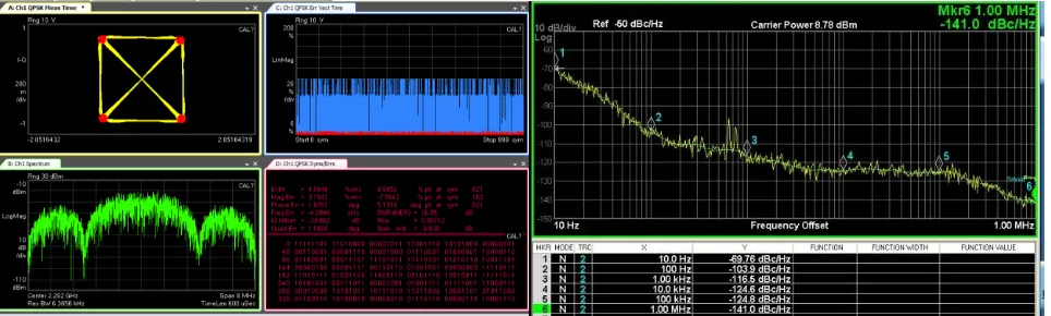
The backward-output power, EVM, phase and amplitude unbalance and carrier phase noise of relay communication terminal can be measured by the spectrum analyzer. It should be noted that attenuator is needed during the testing process to protect the equipment. The channel power values obtained by the spectrum analyzer are not accurate and are usually measured by the power meter. EVM and phase amplitude nonflatness can be directly measured by the agilent N9030A spectrum analyzer plug-in 89601. After switching backward to single carrier mode, carrier phase noise can be measured by using the phase noise testing function of the spectrum analyzer, and the test results are shown in FIG. 3.
Figure 3. Test results of EVM and carrier phase noise of RF signal.
[image:3.595.59.541.424.569.2]Figure 4. Cortex HDR demodulation unit display control interface.
The backward link BER test also uses BES for data checking. However, since the received data frame format from HDR is different from the sent data frame format, extra development of framing software is needed for data frame format conversion.
Application of Flexible Test System
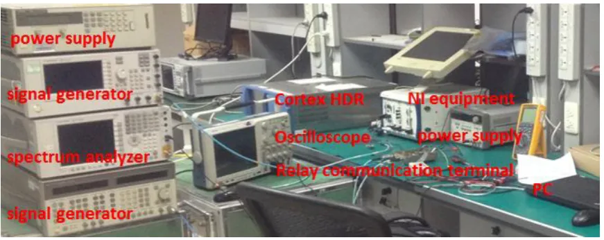
The hardware architecture of the above test system is clear, and the corresponding instrument is the common test equipment in the laboratory, which is convenient and fast to build. The functional requirements of the software part are clear, and the development time is about one week. From design to implementation, the test system has short cycle time and strong operability, which can quickly meet the system test requirements of relay communication terminals. Figure 5 is the picture of the flexible test system hardware platform of relay communication terminals.
Figure 5. The flexible test system hardware platform of relay communication terminals.
[image:4.595.81.517.439.612.2]introduces the idea of open flexible test system, and designs a set of flexible test system for communication terminal, which is used in various ground test systems. The test results show that the test system has a simple framework, high universality of hardware platform, fast software development cycle and low cost, which can meet the test requirements of a considerable number of communication terminals and has great practical value.
Acknowledgement
This research was financially supported by Science and technology innovation key deployment project of Chinese academy of sciences.
References
[1] M. Ishida, K. Ichiyama, An ATE System for Testing 2.4-GHz RF Digital Communication Devices with QAM Signal Interfaces, C. Proc. International Test Conf. (2015).
[2] M. Ishida, K. Ichiyama, An ATE System for Testing RF Digital Communication Devices with QAM Signal Interfaces, J. IEEE Design and Test. 2168(2016) 1-8.
[3] J. Burden, P. A. Curry, D. Roby and F. Love, Introduction to The Next Generation Automatic Test System(NGATS), J. IEEE, 2005.