2019 2nd International Conference on Informatics, Control and Automation (ICA 2019) ISBN: 978-1-60595-637-4
Modeling and Dynamic Behavior Analysis of the ICPT System with
Multiple Receivers
Zhong-ming YU, Yue SUN
*, Xin DAI and Zhao-hong YE
Automation College, Chongqing University, Chongqing, China
*Corresponding author
Keywords: Inductively coupled power transfer system, Modeling, Dynamic behavior, Coupling parameter.
Abstract. This paper investigates modeling and dynamic behavior of inductively coupled power transfer system with multiple receivers. Firstly, by using the idea of decomposition to set up model of the inductively coupled power transfer system with multiple receivers. Then, by simulation, analyzing dynamic behavior of the inductively coupled power transfer system with two receivers. The proposed modeling method is help to clearly illustrate the dynamic behavior of each subsystem. And results indicate variation of coupling parameters has a significant influence on the dynamic behavior of the system.
Introduction
Wireless power transfer technology has attracted more and more people attention in the past several decades due to its wide range of applications such as mobile phones [1], biomedical implants [2] and electric vehicles [3]. Therefore, inductively coupled power transfer (ICPT) system has been investigated deeply by relevant scholars at home and abroad. However, at present, the ICPT system is becoming more complex so as to meet various needs of people, which results in many problems, for example the modeling, the complicated dynamic behavior analysis and so on.
First of all, for the modeling method of the ICPT system, the circuit theory method [4,5] and generalized state space averaging (GSSA) modeling method [6,7] are adopted mainly in past research. Unfortunately, the former is not reveal the dynamic behavior of the ICPT system. For the latter, this modeling method can only be used for analyzing the simple ICPT system. But for the complex ICPT system such as the ICPT system with multiple receivers, this approach will be confronted with the intricate modeling problem. Besides, the dynamic behavior of the ICPT system will be also more complex with the increase of subsystems.
Motivated by the above discussion, in this paper, a novel modeling approach for the ICPT system with multiple receivers is proposed by utilizing the idea of decomposition. This method can not only be used for analyzing the dynamic behavior of the single subsystem, but also for studying the whole system, which can help us to put forward some targeted strategies for locally problematic subsystems to improve the dynamic performances of these subsystems and reduce cost.
The paper is organized as follows. Section 2 describes model of the ICPT system with multiple receivers. In section 3, the dynamic behavior of the ICPT system with multiple receivers is analyzed by simulation when the receive systems are moved randomly. Conclusions are drawn in section 4.
Model Description
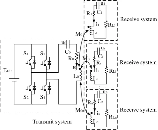
A detailed description of the ICPT system can be found in [8], here we mainly discuss modeling. The ICPT system with multiple receivers is depicted in figure 1. The whole ICPT system consists
of a transmit system and n receive systems. Generally, for the ICPT system with multiple receivers,
parameterMij). By using the circuit theory, differential equations of the ICPT system with multiple
receivers are expressed as follows.
EDC
S1
S2
S3
S4
C0
C1
R0
R1
i0
i1
M0i
RL1
u0
u1
L0
L1
Ci
Ri
ii
Li
Cn
in
Ln
ui
RLi
RLn
...
...
M01
M0n
un
Rn
Transmit system
Receive system
Receive system
[image:2.595.161.430.116.337.2]Receive system
Figure 1. ICPT system with multiple receivers.
0 1
0 0 0 0 01 0
1 0 2
1 01 1 1 1 1 1 12 1
0 1 ( 1)
0 1 ( 1)
0
0 0
1
1 1
( ) ( ) ( )
0
0
n
DC n
n
L n
n n
n n n n n Ln n n n n
n
n n
di di di
s t E u t i t R L M M
dt dt dt
di di di di
L M i R i R u M M
dt dt dt dt
di di di di
L M i R i R u M M
dt dt dt dt
du
C i
dt du
C i
dt
du
C i
dt
(1)
where
1 (2 1)
2 ( )
1 (2 1) ( 1)
2
T
kT t k
s t
T
k t k T
, k is zero or positive integer, Tdenotes a wok circle of
the inverter.
From equations (1), we can see that the model is very complex and highly difficult to analyze directly.Therefore, it is essential to further improve the model.
For 1,
n
j ij j j i
di M
dt
, since Lj
j
jdi
u L dt
, it follows that
1, 1,
( )
Lj
n n
j ij
ij
j j j i j j i
di M
M u t
dt L
, i=0, 1, 2,…, n.Besides, since the ICPT system is in resonance, according to circuit theory, we know that
( ) ( )
Lj j
u t u t . It is noted that due to reciprocity of the mutual inductance, MijMji. Then by using the
0 0
0 0 0
0 0 0 1 0
0
0 0
1 1
1 1 1 1 1
1 1 1 0, 1 1
1 1 1
1
0
1 1 1
( ) ( ) ( ) ( )
1
1 1 1
( )
1
1 1 1
( ) n j DC j j j n j L j j j j n n nj
n n n Ln n j
n n n j n j
di M
s t E u t i t R u t
dt L L L L L
du
i
dt C
di M
i R i R u u t
dt L L L L L
du i
dt C
di M
i R i R u u t
dt L L L L L
d
1 n n n u i dt C (2)Define the state variablexi( , )u ii i T, the state space model of the i-th subsystem is described as
follows.
i i i i i
x A x B v f (3) where 1 0 1 i i i Li i i C A R R L L , 0 0 0 1 B L
, ( 0)
0
0
i i
B
, vdenotes input control, and v t( )s t( )EDC ,
0, 0 n i ij j i j j j i
f M u L L
, i=0, 1, 2,…, n.
Dynamic Behavior Analysis of the ICPT with Multiple Receivers
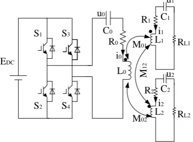
In this section, the dynamic behavior of the ICPT system with two receivers as shown in figure 2 will be analyzed. First of all, the relevant parameters of the system are adopted as follows.
EDC100V, 044367.8rad s/ , L0L1L2127F,R0 6 ,R1R2 3 ,M120.8F,
0 1 2
C C C 4F , M01M0212.7F,RL1100, RL2150, M 12 [0.8 0.8sin( 0t)]H,
01 02 [63.5 63.5sin( 0 )]
M M t H.
EDC S1 S2 S3 S4 C0 C1 R0 R1 i0 i1
M01 RL1
[image:3.595.197.393.635.779.2]L0 L1 C2 R2 i2 RL2 L2 M02 u1 u2 u0 M 1 2
-100 -50
0 50
100
-1 -0.5 0 0.5 1 -1 -0.5 0 0.5
u1 u2
u3
-20 -10
0 10
20
-0.1 -0.05 0 0.05 0.1 -0.1 -0.05 0 0.05 0.1
i1 i2
i3
(a) Phase plot(u1,u2,u3) of the ICPT system (b) Phase plot(i1,i2,i3) of the ICPT system
-100 -50 0 50 100
-20 -15 -10 -5 0 5 10 15 20
u1
i1
-1 -0.8 -0.6 -0.4 -0.2 0 0.2 0.4 0.6
-0.1 -0.08 -0.06 -0.04 -0.02 0 0.02 0.04 0.06 0.08 0.1
u
2 i2
[image:4.595.97.493.87.420.2](c) Phase plot(u1,i1) of the ICPT system (d) Phase plot(u2,i2) of the ICPT system
Figure 3. Phase plots of ICPT system with two receivers when subsystems are not moved randomly.
-150 -100
-50 0
50 100
-30 -20 -10 0 -25 -20 -15 -10 -5 0
u1
u2
u3
-20 -10
0 10
20
-1 -0.5 0 0.5 1 -0.6 -0.4 -0.2 0 0.2 0.4
i1
i2
i3
(e) Phase plot(u1,u2,u3) of the ICPT system (f) Phase plot(i1,i2,i3) of the ICPT system
-150 -100 -50 0 50 100
-20 -15 -10 -5 0 5 10 15 20
u1
i1
-25 -20 -15 -10 -5 0
-0.8 -0.6 -0.4 -0.2 0 0.2 0.4 0.6
u2
i2
(g) Phase plot(u1,i1) of the ICPT system (h) Phase plot(u2,i2) of the ICPT system
[image:4.595.100.485.463.785.2]Phase plots of the ICPT system with two receivers are presented in figure 3 and figure 4 respectively when the positions of the subsystems are not moved randomly and moved randomly. Subplots (a) and (b) show the dynamic behavior of the whole ICPT system with two receivers, and subplots (c) and (d) show the dynamic behavior of the subsystems 0 and 1 respectively.From these figures ,we can see that the ICPT system with two receivers doesnot occur chaos phenomenon and is stable. Then,when the positions of the subsystems are moved randomly, from subplots (e) and (f), it is easily to see that the dynamic behavior of the whole ICPT system becomes very complicated. Besides, from subplots (g) and (h), we can also clearly see the variation of the dynamic behavior of each subsytem, which can help us to more accuately research the dynamic behavior chracteristics of the complex ICPT system.
Summary
In this work, by adopting the idea of decomposition to establish the model of the ICPT system with multiple receivers. Based on the model, the dynamic behavior of the ICPT system with multiple receivers was researched. The simulation results show that the dynamic behavior of the ICPT system becomes more complex with the change of the coupling parameters. The proposed model method has an important guiding significance for the modeling, analysis and control of the complex ICPT system.
Acknowledgement
This research was financially supported by the National Natural Science Foundation of China under Grant 51777022.
References
[1] A. Sample, B. Waters, S. Wisdom, J. Smith, Enabling seamless wireless power delivery in dynamic environments, Proc. IEEE 101(2013) 1343-1358.
[2] H. Jiang, J. Zhang, D. Lan, K. K. Chao,H. Shahnasser, A low-frequency versatile wireless power transfer technology for biomedical implants. IEEE Transactions on Biomedical Circuits and Systems 7(2013)526-535.
[3] M. McDonough, Integration of inductively coupled power transfer and hybrid energy storage system: A multiport power electronics interface for battery-powered electric vehicles, IEEE Trans. Power Electron. 30(2015) 6423-6433.
[4] A. P. Sample, D. A. Meyer, J R. Smith, Analysis, experimental results, and range adaptation of magnetically coupled resonators for wireless power transfer. IEEE Transactions on Industrial Electronics 58(2011) 544-554.
[5] D. Ahn, S. Hong, Effect of coupling between multiple transmitters or multiple receivers on wireless power transfer. IEEE Transactions on Industrial Electronics 60 (2013) 2602-2613.
[6] L. Huang, Y. L. Li, Z. He, S. Gao, J. Yu, Improved robust controller design for dynamic IPT system under mutual-inductance uncertainty. Emerging Technologies: Wireless Power (2015)1-6.
[7] C. Xia, W. Wang, G. Chen, X. Wu, S. Zhou, Y. Sun, Robust control for the relay ICPT system under external disturbance and parametric uncertainty. IEEE Transactions on Control Systems Technology 25 (2017)2168-2175.